
 ?Mathematical formulae have been encoded as MathML and are displayed in this HTML version using MathJax in order to improve their display. Uncheck the box to turn MathJax off. This feature requires Javascript. Click on a formula to zoom.
Abstract
Diamond/copper composites are regarded as a new generation of heat dissipation materials because of their good thermal conductivity and matched thermal expansion coefficient to semiconductor materials. This study focuses on the thermal application study of the diamond/copper composite. A diamond/copper composite cooling module was designed to meet the requirements of thermal physical properties of an electronic device. The heat conduction resistance of diamond/copper substrate was calculated theoretically. It is found that the optimum thickness of diamond/copper substrate is about 0.34 times of the equivalent radius and improving the thermal conductivity of the substrate is more effective for heat dissipation when the thermal convective resistance is low. When the heat flux of the chip is 100 W/cm2, the temperature of the chip using diamond/copper composite as substrate is 4.84 °C lower than that using silicon aluminum alloy. The improvement effect increases about 5 °C when the heat flux increases by 100 W/cm2.
1. Introduction
As science and technology develop, electronic devices play an increasingly important role with the heat flux growing. Traditional heat dissipation materials cannot meet the practical needs. Furthermore, it is necessary to consider the effect of temperature load on the thermal stress among packaging components under actual working conditions.
In order to improve the cooling performance of radar electronic module, high thermal conductivity and low coefficient of thermal expansion (CTE) material is expected to be used in substrate and module shell of the module. Since the CTE of silicon crystal is about 6 × 10⁻⁶ K−1, both the CTE of substrate and module shell must be lower than 8 × 10⁻⁶ K−1. As to the thermal conductivity, the higher the better. Theoretically, the thermal conductivity of diamond is as high as 2200 ∼ 2600 W/(m·K), and the CTE is about (0.86 ± 0.1) × 10−6 K−1 [Citation1–4]. However, pure diamond is difficult and costly to obtain. The proper approach is to use diamond as reinforcement to prepare metal matrix composites. Cu is an alternative with high cost-effectiveness and thermal conductivity reaching 398 W/(m·K). Although Cu has a higher thermal expansion coefficient of 17.5 × 10⁻⁶ K−1 [Citation5], it can be adjusted by adding diamond [Citation6]. Therefore, diamond/copper composite material is a new type of thermal management material with great potential [Citation7–10].
Diamond/copper composite material was first prepared by an American company in the research of heat dissipation materials for chip substrate, and then it was regarded by researchers as a new generation of heat dissipation materials that could replace the existing ones. Many studies had focused on the thermal conductivity of particle reinforced composites, the highest thermal conductivity reported in the literature was between 529 W/(m·K) and 930 W/(m·K) [Citation11].
The commonly used substrate materials currently include Kovar, Invar, Al alloy, Cu/Mo alloy, etc. The thermal expansion coefficients of Kovar and Invar are close to those of chip materials, but their thermal conductivity is very low and their thermal conductivity is poor. Aluminum alloy is relatively light and has high thermal conductivity, but its CTE value is also high; Cu/Mo alloy has ideal CTE and much higher thermal conductivity compared to Kovar and Invar, making it a widely used substrate material in bare chip packaging at present. However, Cu/Mo alloy cannot meet the requirement in the future high heat flux chip packaging and cooling. Diamond/copper composite material is likely to be put into practical application in the near future [Citation12].
Zhang et al. [Citation12] concluded that diamond/copper composites have a good application prospect in bare chip packaging. Via experiment and computer simulation, the feasibility and effect of its application on substrate materials are studied. Through Ansys simulation, it is found that when diamond/copper composite replaces molybdenum-copper alloy as the substrate material, the chip temperature rise can be reduced by up to 24%. Experimentation has concluded that the Au-Sn welding between diamond/copper composite material and chip is feasible with no bubbling in the welding process, but a long heating time is required. It is believed that the welding performance of diamond/copper composite material meets the application requirements. Feasibility of using diamond/copper composites in heat dissipation design of microwave power components was further examined by Zhang et al. [Citation13], with the simulation chip welded after the surface of the composite material was plated with Ni-Au. The welding layer was then tested by shear force, vibration, impact and other environmental factors besides heat-dissipation tests. The results of the many fore-mentioned tests demonstrate that diamond/copper composites can meet various performance and environmental requirements, and have promising application prospects in the thermal design of high-power devices.
In the field of aerospace, diamond/copper composites also have a promising application prospect. For example, with the continuous development of space earth observation technology, requirements for imaging resolution of space-borne cooled infrared detectors are increasing, which leads to increased sensitivity to temperature. Therefore, the cold end interface materials need to meet two requirements: having high thermal conductivity at a low temperature, to keep the working surface temperature uniform enough during operation; keeping the thermal expansion coefficient of the substrate material matched with that of the general structure of the craft to reduce the negative effect on imaging quality due to thermal stress caused by temperature changes. The commonly used Mo-Cu material can hardly meet the demand of temperature uniformity at present. Against this background, Guo [Citation14] successfully prepared diamond copper composite with high thermal conductivity in the temperature range of -173 °C to 72 °C with thermal expansion coefficient meeting the requirements. The composite has a thermal conductivity of 650 W/(m·K) at room temperature which decreases to 600 W/(m·K) at -173 °C and a thermal expansion coefficient of 5.0 × 10⁻⁶/K, proving that it can adapt to the low operating temperature on spacecrafts. Furthermore, considering the temperature change caused by the change of relative position with the sun and the influence of pulse current in space environment, a series of high and low temperature cycle impact tests on diamond/copper composites were conducted to study the properties of the material under such influences. The results show that the properties of diamond/copper composites can still meet the relevant requirements without any considerable changes after the high temperature and low temperature cycles. The above research indicates that diamond/copper composite is suitable for low temperature conditions in space environment, and not only can be used to improve the imaging quality of long-line stitching infrared detectors, but also has applicational potential for all devices requiring temperature uniformity.
Diamond/copper composites with high thermal conductivity have good application prospects, such as the gripper rod of high-power traveling wave tube, the heat dissipation substrate of active phased array antenna, the heat dissipation of neutralizer of satellite ion thruster, the outer ring of Hall thruster, the packaging material of satellite-borne large-scale integrated circuit and CPU, the heat dissipation of high-power LED lighting, etc [Citation11, Citation15]. For example, in high power LED lighting, diamond/copper is considered a competitive new heat dissipation material. Fan et al. [Citation16] coated the surface of diamond/copper composite with 10 μm silver coating, made a near-net radiator instead of high-power LED radiator, hence meeting the space applicational requirements of volume and mass through reducing the weight of the internal radiator by more than 35%, the LED thermal resistance by 10.5% and the junction temperature by 33.3%. The service life of LED devices can be greatly extended and the reliability of equipment can be greatly improved with the future practical application of such technology.
When diamond/copper composites are used in actual heat dissipation and packaging materials for electronic devices, other parameters such as size and external heat transfer condition also have significant impact on the overall heat dissipation performance. However, there is not enough literature reports in this field. This study will develop a typical 3D model of chip packaging for high-power chips electronic device components. The thermal performance of using diamond/copper composites instead of traditional silicon aluminum alloy packaging material will be studied by conduct thermal simulation. The heat conduction resistance of diamond/copper substrate will also be calculated theoretically to find out the relation between optimum thickness of diamond/copper substrate and equivalent radius.
2. Analysis model
With the application of the third-generation semiconductor materials such as GaN and the development of phased array technology, the equipment of microwave components of spaceborne radar keeps increasing, so as the heat generated per unit volume [Citation17]. However, the effective heat dissipation area decreases correspondingly, and the power density increases rapidly. If the problem of heat dissipation cannot be solved effectively, the reliability and lifetime of spaceborne radar will be seriously affected. The existing ceramic substrate materials have been unable to meet the heat dissipation requirements, and the high-power components such as GaN chips are often directly welded to the heat sink of metal materials with higher thermal conductivity. Currently, diamond/copper composite, with its high thermal conductivity and thermal expansion coefficient matching with semiconductor materials, surpasses the traditional metal packaging materials, and have great advantages in the field of high-power electronic device packaging. When selecting substrate materials, multiple factors need to be considered, such as high thermal conductivity, high heat resistance, high strength, high reliability, low CTE, low moisture absorption, low dielectric constant, and so on. In this study, it is mainly focused on high thermal conductivity of the material, size and the matching of the cooling parameters.
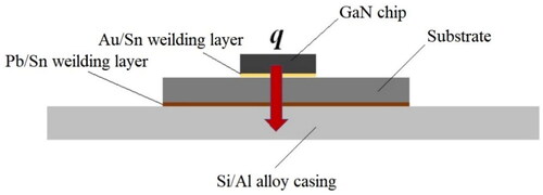
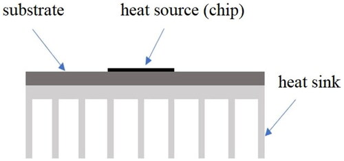
Based on the above background, this section establishes a 3D model of the chip packaging for high-power chips as shown in . In , the four chips are the same size (3 mm×3 mm). The substrates are under the chips, there are two kinds substrates, one kind is traditional packaging material (shown in grey in ) and another kind is diamond/copper composite (shown in golden in ). The thermal simulation analysis on this model is to study the enhancement of the heat dissipation effect of diamond/copper composites compared with traditional packaging materials. The size of the module is fixed at 120 mm×240 mm, and other parameters of all the chips are the same. When traditional silicon aluminum alloy packaging material was used as the substrate, the schematic diagram of the thermal conduction path of the chip in this model was shown in . In , q was the heat flux of the chip, and the red arrow represented the heat transfer direction. Different sizes and thickness of substrates and different thickness of the module shell were studied by conduct thermal simulation using FloEFD software.
Figure 1. A typical structure c model of high-power chips electronic device component.
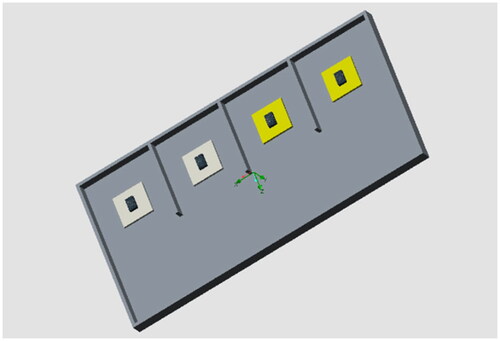
Figure 2. Structure schematic diagram of the heat conduction path of the chip.
Thermal simulation is conducted to simulate and analyze the improvement effect of diamond/copper composites on heat dissipation of high-power chips according to the above model.
3. Results and discussions
3.1. Simulation analysis on heat dissipation effect of diamond/copper composite applied to spaceborne radar
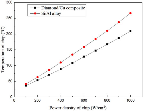
As shown in , when diamond/copper composite material and traditional aluminum alloy material are respectively used as the cooling substrate of high-power chips, with the increase of chip heat flux, the temperature rise of chips using diamond/copper composite material as the cooling substrate is significantly slower than that using aluminum alloy. As the heat flux increases from 100 W/cm2 to 1000 W/cm2, the temperature gap between the two test subjects increases from 4.84 °C to 57.38 °C. Heat flux increase of every 100 W/cm2 results in an enlargement of the temperature gap by about 5 °C. The results reported in the literature indicate that 10 °C increase in junction temperature of common chip can shorten the service lifetime of the electronic chip by 50% [Citation18]. The use of diamond/copper composite material with higher thermal conductivity as the substrate material is of great significance to improve the life-span and reliability performance of electronic equipment such as spaceborne radar.
Figure 3. Chip temperature rise of different substrate heat dissipating materials.
3.2. Influence of substrate size parameters on its thermal conductive resistance
The results reported in the literature [Citation19] indicate that rectangular shaped heat sources and thermal expansion layers can be equivalent to circular heat source and thermal expansion layer and the principle of equivalence was that the cross-sectional area and thickness remained unchanged as shown in .
Figure 4. Equivalent changes between rectangular heat sources and thermal expansion bodies and circular heat sources and thermal expansion bodies.
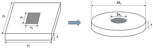
The parameters in can be calculated as follow:
(1)
(1)
(2)
(2)
(3)
(3)
where, ae is equivalent radius of the heat source, be is equivalent radius of the substrate, t is thickness of the substrate.
The control equation can be written as an equation in the following cylindrical coordinate form as follow [Citation20, Citation21]:
(r·k
k
(4)
The Boundary is:
(5)
(5)
(6)
(6)
(7)
(7)
(8)
(8)
where, T is temperature difference from the heat source to ambient, q is the heat flux of the heat source, h0 is convective heat transfer coefficient of the substrate, k is thermal conductivity of the substrate.
Lee et al. [Citation20, Citation21] developed the simplified solution of dimensionless average total thermal conductive resistance and maximum total thermal conductive resistance as follow:
(9)
(9)
(10)
(10)
where,
is the dimensionless equivalent radius of the substrate,
=
; τ is the dimensionless thickness of the substrate, τ =
; Bi is Biot number, Bi =
; Φc=
; μc = π +
.
Therefor, maximum total thermal conductive resistance can be calculated as follow:
(11)
(11)
where, As is the area of heat source, Thm is maximum temperature of the heat source, is average temperature of the substrate.
This study investigated the thermal performance of the typical chip cooling model as shown in .
Figure 5. The thermal model of heat source (chip).
shows the influence of the equivalent radius of the substrate on the total thermal conductive resistance when the thickness of the substrate took different values. The equivalent radius of heat source ae=10mm, external convection heat transfer coefficient h = 500W/(m2·K), k = 500W/(m·K), and the substrate material was diamond/copper composite.
Figure 6. Influence of equivalent radius of substrate on total thermal conductive resistance under different substrate thicknesses.
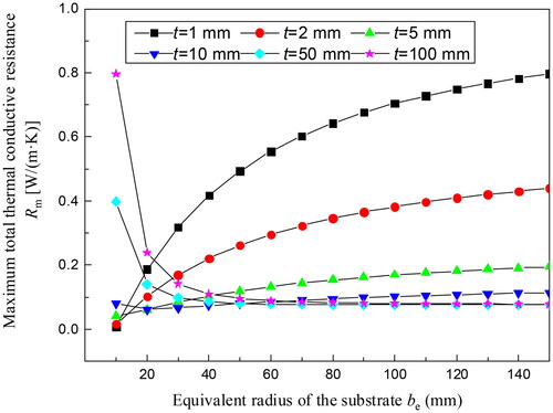
When the thickness of the substrate is different, the influence of the equivalent radius of the substrate on the maximum total thermal conductive resistance is not the same. In general, when the substrate thickness is small, the total thermal conductive resistance increases with the increase of the equivalent radius of the substrate. When the thickness of the substrate increases to a certain value, the total thermal conductive resistance decreases first and then increases slowly to a steady state with the increase of the equivalent radius of the substrate. This is because when t is very small, the proportion of one-dimensional thermal conductive resistance among the total value is very small, and the change of total thermal conductive resistance mainly depends on the expansion thermal resistance, that is, the larger the equivalent radius of the substrate, the larger the expansion thermal resistance, and the larger the total thermal conductive resistance. When t gradually increases, the proportion of one-dimensional thermal conductive resistance also increases, and the total thermal conductive resistance will first decrease and then increase with the change of the substrate radius. In order to analyze the influence law of substrate radius on the total thermal conductive resistance more accurately, multiple sets of data were calculated by changing the equivalent radius of heat source and convective heat transfer coefficient, and the critical substrate thickness when the influence law of the equivalent radius of substrate on the maximum total thermal conductive resistance changes are listed in .
Table 1. Data of critical substrate thickness under different parameters.
According to the above calculation and analysis, the critical substrate thickness is only related to the equivalent radius of heat source. When the substrate thickness is less than 0.6 times the equivalent radius of heat source, the larger the equivalent radius of substrate be is, the bigger Rm is, and the latter tends to gradually stabilize; when the substrate thickness is greater than 0.6 times the equivalent radius of heat source, as the radius be enlarges, Rm gets smaller at first well then gradually increases till stabilizing.
Therefore, when t < 0.6ae, the substrate radius should be minimized to reduce thermal conductive resistance; when t > 0.6ae, there is an optimal be* to minimize Rm. demonstrates the variation of optimal substrate radius be* as substrate thickness changes.
Figure 7. The variation of optimal substrate radius be* as substrate thickness changes.
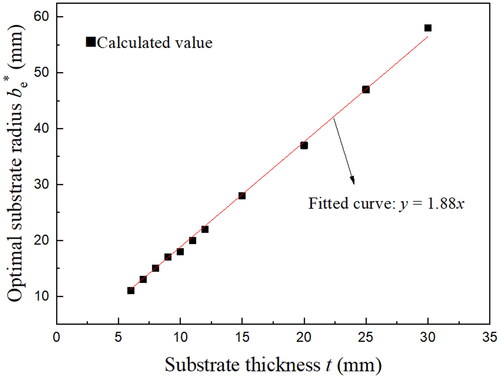
A linear fit gives be*≈1.88t, i.e. the equivalent radius of the substrate should be about 1.88 times of the substrate thickness when the latter value is greater than 0.6ae.
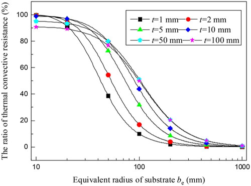
However, since the equivalent radius of the substrate has a great influence on the thermal convective resistance, not only its influence on the thermal conductive resistance, but also on the thermal convective resistance R0 should be fully considered. gives the total thermal resistance (sum of total thermal conductive resistance Rm and thermal convective resistance R0) as a function of the equivalent radius of the substrate. The total thermal resistance decreases rapidly and then increases slowly with the increase of the equivalent radius of the substrate, regardless of the substrate thickness. Thermal convective resistance R0 is inversely proportional to the equivalent radius of the substrate. As shown in , the thermal convective resistance R0 takes up a considerable proportion of the total resistance within a certain range of be, so that the total thermal resistance is mainly decreased by the influence of R0. For this reason, the rising trend of the thermal conductive resistance with the rise of be can be ignored, and the equivalent radius of the substrate, namely the heat dissipation area, is often increased to enhance the heat dissipation in actual engineering. Of course, the total thermal resistance has been gradually stabilized when be gets necessarily large and be should not be further enlarged to little effect at this point. If be is further enlarged, thermal conductive resistance will become the main factor of the total resistance, which increases as be does when be is large enough, as shown in above. The total thermal resistance will increase, which is not conducive to heat dissipation.
Figure 8. Change of total thermal resistance with equivalent radius of substrate under different substrate thicknesses.
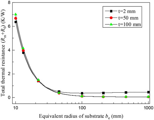
Figure 9. The ratio of thermal convective resistance to total thermal resistance with the equivalent radius of substrate under different substrate thicknesses.
shows the influence of substrate thickness on the total thermal conductive resistance by theoretical calculation when the equivalent radius of the substrate was taken to different values. The equivalent radius of heat source ae=0.01 m, the external convective heat transfer coefficient h = 500 W/(m2·K), the material of the substrate was diamond/copper composite, k = 500 W/(m·K).
Figure 10. Influence of substrate thickness on total thermal conductive resistance under different substrate equivalent radius.
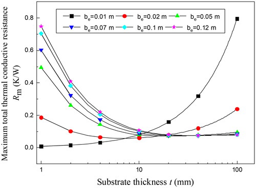
When the equivalent radius of the substrate is consistent with the heat source, the heat conduction can be regarded as one-dimensional, there is no expansion thermal resistance, and the total thermal resistance increases with the increase of the substrate thickness. When the equivalent radius of the substrate is different from that of the heat source, the expansion thermal resistance is generated, and within a certain range, the total thermal conductive resistance decreases with the increase of the thickness of the substrate t. This is because expansion thermal resistance is essentially heat conduction which is not fast enough, resulting in a high-temperature area near the heat source. When the thickness of the substrate is small, the thermal diffusion capacity of the substrate material exceeds its thickness. Therefore, the heat can be smoothly conducted out from the thickness direction thus alleviating the accumulation of heat in the transverse direction of the substrate, so that the increase in the thickness of the substrate does not aggravate the accumulation of heat in the axial direction. Therefore, the expansion thermal resistance is reduced, and the one-dimensional thermal conductive resistance increases slightly, which does not affect the overall reduction of the total thermal conductive resistance. However, one-dimensional thermal conductive resistance continues to increase with the increase of substrate thickness. When t increases to a certain extent, the improvement effect on expansion thermal resistance cannot offset the increase of one-dimensional thermal resistance, and the total thermal resistance gradually becomes stable and then rises slowly.
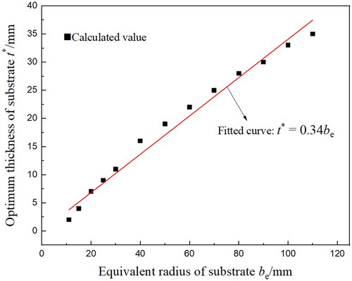
When the equivalent radius of the substrate is constant, there is an optimal substrate thickness t* to minimize the maximum total thermal conductive resistance. The optimal substrate thickness under different be conditions are showed in . It can be seen from that the optimum thickness of diamond/copper substrate is about 0.34 times of the equivalent radius. Improving the thermal conductivity of the substrate is more effective for heat dissipation when the thermal convective resistance is low.
Figure 11. The optimal substrate thickness under different be conditions.
3.3. Influence of external convective heat transfer coefficient on thermal conductive resistance
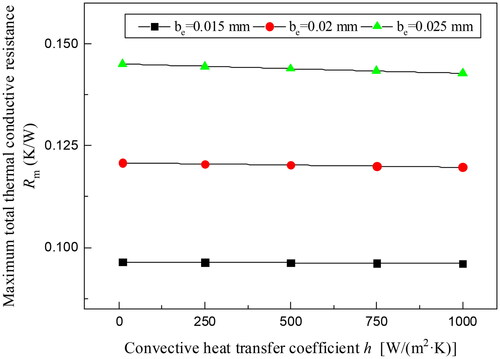
shows the changes of the total conductive heat resistance with the convective heat transfer coefficient under different equivalent radius of the substrate. The external convective heat transfer coefficient has little influence on the maximum total thermal conductive resistance, which is because the total thermal conductive resistance consists of two parts: expansion thermal resistance and one-dimensional thermal conductive resistance. The expansion thermal resistance comes from the size difference between the heat source and the substrate, and the one-dimensional thermal conductive resistance is determined by the properties of the substrate itself and its thickness. Both of which has little relationship with the external environment.
Figure 12. Maximum total thermal conductive resistance as a function of convective heat transfer coefficient.
3.4. Influence of substrate thermal conductivity
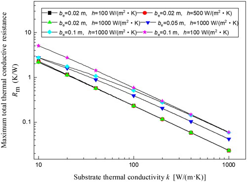
shows the thermal conductive resistance and its proportion in total thermal resistance (sum of total thermal conductive resistance and thermal convective resistance) as a function of the substrate thermal conductivity k under the conditions of different convective heat transfer coefficients and equivalent radius of the substrate. Obviously, with the increase of k, the thermal conductive resistance decreases while the thermal convective resistance is independent of k, thus the proportion of thermal conductive resistance naturally decreases. In fact, the extension thermal resistance is essentially caused by the fact that heat accumulates on the contact surface between the heat source and the substrate and cannot diffuse to the surroundings very well. The higher the thermal conductivity of the material, the faster the heat can be transferred around, and the better the heat dissipation effect. Therefore, substrate materials should be made of materials with high thermal conductivity to minimize heat concentration and thus reduce expansion thermal resistance.
Figure 13. Maximum total thermal conductive resistance as a function of substrate thermal conductivity under different conditions.
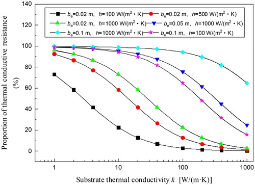
In addition, it can be seen from that with the increase of convective heat transfer coefficient and equivalent radius of substrate, thermal convective resistance decreases, and the proportion of thermal conductive resistance increases over all. The power of the heat source is increasing in engineering applications with the development of technology, hence ever higher external convective heat transfer coefficient and ever larger heat dissipation area are usually needed, which means that the influence of conductive heat resistance is increasing. At this time, the effect of reducing the total heat resistance through the adjustment of heat dissipation area or the improvement of external convective heat transfer is limited. The use of substrate or thermal expander with higher thermal conductivity to derive heat has become a more effective way. The diamond/copper composite material prepared in this study, with its higher thermal conductivity compared to the existing heat dissipating materials, can further lower the barrier of transferring excess heat to the outside when the external convection heat dissipation of the chip is limited or reaches the bottleneck, so as to reduce the temperature of the chip and achieve the purpose of thermal management.
Figure 14. Changes of the proportion of thermal conductive resistance in total thermal resistance with the substrate thermal conductivity under different conditions.
4. Conclusions
This study developed the thermal application study of the diamond/copper composite. A diamond/copper composite cooling module was designed to meet the requirements of thermal physical properties of an electronic device. The heat conduction resistance of diamond/copper substrate was calculated theoretically. The following main conclusions are obtained:
The optimum thickness of diamond/copper substrate is about 0.34 times of the equivalent radius, and improving the thermal conductivity of the substrate is more effective for heat dissipation when the thermal convective resistance is low.
When the heat flux of the chip is 100 W/cm2, the temperature of the chip using diamond/copper composite as substrate is 4.84 °C lower than that using silicon aluminum alloy. The improvement effect increases about 5 °C when the heat flux increases by 100 W/cm2.
Author contributions
Jinwang Li: conceptualization, methodology, investigation, formal analysis, resources, writing manuscript, supervision, project administration, funding acquisition; Tianshu Cong: data curation, writing—draft preparation; Shugang Dai: data curation, writing—original draft preparation.
Disclosure statement
No potential conflict of interest was reported by the authors.
Additional information
Funding
References
- Ye W, Wei Q, Zhang L, et al. Macroporous diamond foam: a novel design of 3D interconnected heat conduction network for thermal management[J]. Materials & Design. 2018;156:1–9.
- Lu W, Li J, Miao J, et al. Application of high-thermal-conductivity diamond for space phased array antenna[J]. Functional Diamond. 2021;1(1):189–196.
- Deng J, Zhang H, Fan T, et al. Recent progress on interface and thermal conduction models of diamond/copper composites used as electronic packaging material[J]. Mater Reports. 2016;30(3):19–28. (in Chinese).
- Tao J, Zhu X, Tian W, et al. Properties and microstructure of Cu/diamond composites prepared by spark plasma sintering method[J]. Trans Nonferrous Met Soc China. 2014;24(10):3210–3214.
- Mousavi SE, Naghshehkesh N, Amirnejad M, et al. Corrosion performance and tribological behavior of diamond-like carbon based coating applied on NiAlbronze alloy[J]. Trans Nonferrous Met Soc China. 2021;31(2):499–511.
- Zhao Y, Liu K, Lu D, et al. Research status and prospect of CD/Cu composite for electronic packaging material[J]. Heat Treatment Technol Equipment. 2013;34:31–36. (In Chinese)
- Dai S, Li J, Dong C. Research progress on preparation methods of high thermal conductivity diamond/copper composites[J]. Fine Chem. 2019;36:1995–2008. (In Chinese)
- Wei C, Xu X, Wei B, et al. Effect of diamond surface treatment on microstructure and thermal conductivity of diamond/W-30Cu composites prepared by microwave sintering[J]. Diamond Relat Mater. 2020;104:107760.
- Liu X, Sun F, Wang L, et al. The role of Cr interlayer in determining interfacial thermal conductance between Cu and diamond[J]. Appl Surf Sci. 2020;515:146046.
- Dai S, Li J, Wang C. Preparation and thermal conductivity of tungsten coated diamond/copper composites[J]. Trans Nonferrous Met Soc China. 2022;32(9):2979–2992.
- Dai S, Li J, Lu N. Research progress of diamond/copper composites with high thermal conductivity. Diamond Relat Mater. 2020;108:107993.
- Zhang L, Qian J, Kong X, et al. Research on performance of diamond/copper composite substrate based on bare die packaging[J]. Electro-Mech Engin. 2011;27(06):28–30.
- Zhang L, Qian J, Niu T, et al. Application research of diamond/copper in solid-state microwave power devices[J]. Electro-Mech Engin. 2017;33(6):55–58.
- Guo H. Research on diamond/Cu composites for aerospace application under cold temperature[D]. University of Science and Technology Beijing; 2015.
- Zhang X, Guo H, Yin F, et al. Improving method of interface bonding state in diamond/Cu composite material[J]. Rare Met. 2013;37(2):335–340.
- Fan Y, Guo H, Xu J, et al. Pressure infiltrated Cu/diamond composites for LED applications[J]. Rare Met. 2011;30(2):206–210.
- Ji X, Lai J. Application of ultrahigh thermal conductivity diamond copper composite materials on the GaN device[J]. Adv Packaging Technol. 2017;42(4):310–314.
- Li J. Capillary pumping performance of porous structure and its preparation and optimization for loop heat pipe[D]. Shandong University, 2011. (In Chinese)
- Muzychka Y, Culham R, Yovanovich M. Thermal spreading resistances in rectangular flux channels: part I geometric equivalences[C]. 36th AIAA Thermophysics Conference, 2003: 1–10.
- Lee S, Song S, Au V, et al. Constriction/spreading resistance model for electronics packaging[J]. ASME/JSME Thermal Engineering Conference, 1995: 199–206.
- Song S, Lee S, Au V. Closed-form equation for thermal constriction/spreading resistances with variable resistance boundary condition[C] Proceedings of the International electronics packaging conference, 1994: p. 111–121.