ABSTRACT
Produced water contains salts and minerals of sufficiently high content (salinity > 35%) to be harmful to the ecosystem, making it difficult to dispose of, reinject for enhanced oil recovery, or use for other purposes such as human use and agriculture. This research summarises produced water treatment methods and their ranges of applicability and provides a comprehensive review of the most common desalination techniques used globally for high-salinity waters, explaining their mechanism, applications, advantages and limitations. We provide recommendations on the use of different methods for the desalination of hydrocarbon-associated produced water.
ABSTRAIT
L'eau produite contient des sels et des minéraux d'une teneur suffisamment élevée (salinité > 35 %) pour être nocive pour l'écosystème, ce qui rend difficile son élimination, sa réinjection pour la récupération assistée du pétrole ou son utilisation à d'autres fins telles que l'usage humain et l'agriculture. Cette recherche résume les méthodes de traitement de l'eau produite et leurs domaines d'applicabilité et fournit un examen complet des techniques de dessalement les plus couramment utilisées dans le monde pour les eaux à haute salinité, expliquant leur mécanisme, leurs applications, leurs avantages et leurs limites. Nous fournissons des recommandations sur l'utilisation de différentes méthodes pour le dessalement des produits associés aux hydrocarbures eau produite.
1. Introduction
One of the most problematic challenges facing many countries worldwide is water scarcity and drinking water shortages. This is a result of large water consumption due to an increase in global population, and global warming effects that result in the vaporisation of many natural water sources such as lakes and rivers. One of the most abundant sources of water, in addition to seawater, is referred to as produced water.
Produced water is well known in the petroleum industry as water that comes out of the petroleum reservoirs along with gas and oil during their production. Produced water has properties that are different from those of brackish, seawater, and groundwater aquifers. These properties depend on the crude oil production, treatment and storage as well as the properties of the petroleum reservoir itself. Usually produced water contains many impurities, such as traces of dissolved and suspended oil, organic materials, dissolved and suspended solids (salts), traces of various earth elements, chemicals used during the production of oil and gas, and sand particles (Abdel-Aal, Citation1998; Abdel-Aal & Shaikh, Citation1977; Abdel-Aal et al., Citation2016; Arnold & Stewart, Citation2008).
The volume of produced water is very large and varies from well to well, field to field, and over the life cycle of the well during primary, secondary and tertiary production phases. Usually, the ratio of produced water to oil is greater than 3:1 (3 barrels of water to 1 barrel of oil) and in some fields during their last stage of production the ratio may rise past 20:1 (Veil et al., Citation2004). If the daily global production of oil is 100,000,000 barrels, then the water produced along with the oil ranges from 300,000,000 to 2,000,000,000 barrels per day (47,696,188 to 317,974,590 m3). In addition to increased produced water volumetric flowrate, its composition varies with time. Produced water is usually highly saline, with a total dissolved salt concentration of up to 350,000 ppm in many cases (Abdel-Aal et al., Citation2016) – almost 10 times the salinity of seawater. High salinity makes the produced water unfit for irrigation, municipal, or human use without proper treatment and desalination (Fillo et al., Citation1992; United Nations, Citation2017; Webb et al., Citation2009).
Nowadays, seawater (brine) desalination processes are frequently used to provide fresh water for agricultural and human consumption. Seawater is abundant in ions such as calcium (Ca2+), sodium (Na+), potassium (K+), magnesium (Mg2+), chloride (Cl−), and sulphate (SO24−). These six ions make up about 99% percent of all sea salts by weight. shows the acidity, total dissolved solids (TDS) and ionic content of different seawater samples. Desalination of hydrocarbon-associated produced water is much more challenging due to the presence of the other impurities mentioned above, which require highly efficient pre-deslination treatment.
Table 1. Seawater (brine) physiochemical properties.
Many desalination methods have been introduced, each with its advantages and limitations. These include evaporation and condensation pre-desalination methods, which rely on thermal energy to vaporise the water (Al-Karaghouli & Kazmerski, Citation2013; Bahar et al., Citation2004; Chandrashekara & Yadav, Citation2017; Deniz, Citation2012; Desalination and Water Recycling, Citation2018; Evans & Miller, Citation2002; Hisham & El-Dessouky, Citation2002; Jitendra et al., Citation2013; Talaeipour et al., Citation2017; Xu, Citation2005; Zimerman, Citation1994); filtration desalination methods, which rely on membrane technologies for water filtration (Abdunnabi et al., Citation2021; Compain, Citation2012; Dow et al., Citation2016; Ismail et al., Citation2019; Khan & Al-Ghouti, Citation2021; Silva et al., Citation2011; Thomas et al., Citation2017; Ullah & Rasul, Citation2019; Younos & Tulou, Citation2009); and crystallisation desalination methods, which are phase-change techniques that rely on the crystallisation of the solid components in the saline water for desalination (Ahmad, Citation2012; Jitendra et al., Citation2013; Tlili et al., Citation2019). Although much research has been conducted on the utilisation of these methods for seawater desalination, little research has provided a review of the applicability of these methods for the desalination of hydrocarbon-associated produced water and the advantages and drawbacks of each method from this perspective.
This article summarises the available produced water treatment technologies and provides a review of the most common desalination methods used globally. Through explaining their mechanism, advantages, and limitations, we provide a recommendation on the ability of each method to be used for the desalination of hydrocarbon-associated produced water. This can help provide a foundation for tapping into a source of water that is extremely abundant yet usually avoided due to its complex composition and impurities (Xu et al. Citation2019; Zhu et al., Citation2021).
2. Produced water
The produced water from oil and gas reservoirs, collected from any stage of oil–gas–water separation or oil treatment and desalting systems, and sometimes from the flowback of hydraulic fracking fluid, is highly saline (compared to seawater) and contains concentrations of hydrocarbons and other impurities that are too high for safe environmental disposal or injection into water-injection wells for the purpose of enhanced oil recovery. Produced water must be treated to remove all impurities and then must be desalinated to bring the salt content down to usable standards (Abdel-Aal, Citation1998; Abdel-Aal & Shaikh, Citation1977; Abdel-Aal et al., Citation2016; Arnold & Stewart, Citation2008).
During produced water treatment the main objective is to remove the free oil droplets, gas content and total suspended solids (TSS) from the highly saline produced water. Different methods and equipment, shown in , are used to remove the free oil and gas and TSS, such as filters, precipitators, skim tanks and vessels, hydrocyclones, plate coalescers, and flotation units (Abbas et al., Citation2021; Abdel-Aal, Citation1998; Abdel-Aal et al., Citation2016; Arnold & Stewart, Citation2008; Veil et al., Citation2004).
Table 2. Produced water treatment methods.
3. Desalination techniques
Desalination techniques can be classified under three broad categories – evaporation and condensation; filtration; and crystallisation – as presented in . Each category is named based on the general procedure by which it is conducted. For each broad category, several water desalination methods exist (Curto et al., Citation2021).
Figure 1. Desalination techniques.
Evaporation and condensation desalination techniques are generally used for civil freshwater production. The main idea of this technique is to supply thermal energy to brine to produce a vapour, and then condensate it. The required heat can be generated through a mechanical process or a thermal process (i.e. fuel combustion or waste heat). The mechanical process used to produce fresh water by evaporating the brine and condensing the vapour is called mechanical vapour compression (MVC). Regarding thermal processes, the most common techniques are multi-stage flash distillation (MSF), multi-effect distillation (MED), membrane distillation (MD), and thermal vapour compression (TVC). Various novel approaches that use solar radiation are still under investigation, such as solar still distillation (SSD), humidification–dehumidification (HDH) and solar chimney desalination (SCD) (Bahar et al., Citation2004; Zimerman, Citation1994).
Regarding filtration techniques, all methods are mainly based on the use of a semipermeable membrane, such as a layer with different crossing behaviour modes according to the sizes of molecules. The only different technique is the use of ion-exchange resin (IXR), in which artificial or natural materials are used to extract the dissolved ions in the brine. In filtration techniques, reverse osmosis (RO) is the most common desalination process. IXR and electrodialysis (ED) are used to produce fresh water with a very low salt concentration. Other techniques such as nanofiltration (NF), forward osmosis (FO), and capacitive deionisation (CDI) are still under development (Pérez-González et al., Citation2012; Václavíková et al., Citation2017).
The crystallisation category includes desalination techniques that are based on the extraction of fresh water by producing ice as an intermediate product. The main such techniques are hydration (HY) and secondary refrigerant freezing (SRF) desalination. All processes in this category are still under investigation (Curto et al., Citation2021).
3.1. Evaporation and condensation desalination techniques
3.1.1. Mechanical vapour compression (MVC)
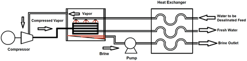
MVC is a common desalination technique based on liquid–vapour phase change. The vapour produced inside the chamber is extracted using a vapour compressor as shown in . The vapour increases in pressure and temperature due to the compression process. In the heat exchanger, heat is transferred from pressurised vapour to the saline water and produces more vapour. To reduce the energy consumption in this process, the heat is transferred from the condensed feedwater and the brine discharge to the saline water feed by a heat recovery exchanger. After the preheating process, the brine recirculation flow is mixed with the saline water. The solution is then sprayed externally on the main heat exchanger in the desalination unit (Zimerman, Citation1994).
Figure 2. Illustration of the MVC desalination technique.
3.1.2. Multi-effect distillation (MED)
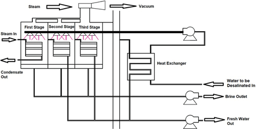
MED is a common thermal-based technique that is widely used for water desalination. MED is carried out in a series of stages and uses principles of evaporation and condensation at ambient pressure, as shown in . The heat that causes the evaporation in the first stage is provided by steam from a boiler, and in the second stage the vapours formed are used to heat the water to be desalinated. Some of the saline water vaporises, leaving behind a more saline solution than the original saline water. The high-pressure vapour from each stage is used to heat the water in the subsequent stage at a lower pressure than the previous stage. The water vapour of the first and second stages is used as a heating agent for the second and third stages, respectively. While this sequence is replicated in all subsequent stages to improve the efficiency of the overall system, the basic method uses condensation to transfer heat to the next batch of saline water, resulting in the separation of distilled water and producing more water vapour as the stages progress. The more stages are used in the system, the higher the performance ratio and efficiency. According to the arrangement of the tubing of the heat exchanger, MED units can be classified as vertical tubes, horizontal tubes, or vertically stacked tube bundles (Bahar et al., Citation2004; Xu, Citation2005).
Figure 3. Illustration of the MED desalination technique.
3.1.3. Multi-stage flash distillation (MSF)
MSF is a thermal desalination technique that employs water evaporation and condensation. illustrates the MSF technique (Evans & Miller, Citation2002). The evaporation and condensation stages are coupled in the process so that the latent heat of evaporation is recovered to be reused. The saline water is heated in the saline water heater, up to a temperature of 100–120°C, and then the vapour flows into a stage in which the ambient pressure is low, causing water to boil. The saline water feed is then moved to a flash unit via a series of chambers through sequential low-temperature and low-pressure steam and is then condensed on tubes passing through the stages. The high-saline brine is discharged from the final flash unit while water exits in the form of condensed vapour (Talaeipour et al., Citation2017).
Figure 4. Illustration of the MSD desalination technique.
3.1.4. Thermal vapour compression (TVC)
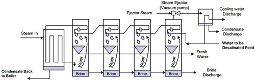
TVC is a common thermal desalination technique based on liquid–vapour phase change, as shown in . The TVC system is also called thermal compression or heat effusion, and is generally similar to a mechanical vapour compression system. The only difference is that a thermal steam compressor is used instead of a mechanical compressor. In the TVC technique the steam mixture, which contains part of the steam produced in the distiller and driving steam produced in a boiler, heats the feed water to be desalinated in the distiller. The steam is then condensed as saturated water. Some of the condensates are moved to the boiler and the rest is mixed with the distiller-desalinated water (Jitendra et al., Citation2013).
Figure 5. Illustration of the TVC desalination technique.
3.1.5. Solar still desalination (SSD)
Solar stills are used to produce fresh water from saline water in a very simple, cheap and easy way. SSD is recommended for people living in remote places as a small-scale desalination system that can provide fresh water. A good aspect of the SSD technique, illustrated in , is that when the demand for fresh water is at its peak solar insolation is also high, especially in summer (Deniz, Citation2012). The solar irradiation passes through the still cover and falls onto the black bottom surface, causing the surface and the contained saline water to heat up. The hot water evaporates and the vapour condenses on the inner side of the still cover; it is collected by condesate channels while flowing on the inner side of the still. The still cover is designed with a tilt angle for the freshwater drops to fall via gravity towards the distilled water condensate channel (Deniz, Citation2012).
Figure 6. Illustration of the SSD desalination technique.
3.1.6. Humidification–dehumidification desalination (HDH)
HDH is a carrier gas-based thermal desalination method. In this system, as shown in , fresh water is obtained by condensing the air humidity. The main components of the system are the humidifier and the dehumidifier. A heat pump can be added to improve the system’s energy efficiency with three circuits: water, air and Freon refrigerant. The Freon refrigerant is kept inside the pipes and the main components of the heat pump. A fan is used to circulate the air in a closed loop, moving through two chambers, in which the humidification and the dehumidification occur. The water circuit is open, where the saline water is the system input, and fresh water and the rejected brine are the system outputs (Al-Karaghouli & Kazmerski, Citation2013). The condenser of the heat pump first refrigerates the saline water. The cold-feed saline water is used to enhance the condensation of air humidity in the dehumidification chamber, in which distilled water is produced. The feed saline water temperature raises, and after that the saline water is nebulised in the humidification chamber, enhancing the evaporation of the saline water (Desalination and Water Recycling, Citation2018).
Figure 7. Illustration of the HDH desalination technique.

3.1.7. Solar chimney desalination (SCD)
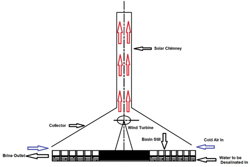
SCD, also known as solar updraught, is a tower-based technology that generates a hot airflow using incident solar radiation, as shown in . The SCD system typically consists of a tower connected to a translucent collector or a cover and opened at the edges. Solar radiation raises the temperature of the ground under a collector, which heats the air inside the chimney. The hot air moves towards the unit centre and runs wind turbines, generating electricity. The solar chimney can be operated in the absence of solar radiation as the ground underneath the collector acts as a natural heat storage system (Fasel et al., Citation2013). The solar collector comprises of a group of small SSD units; in this way, the solar source is also used to produce fresh water. This technique is still under investigation (Sharon & Reddy, Citation2015).
Figure 8. Illustration of the SC desalination technique.
3.2. Filtration desalination techniques
3.2.1. Forward osmosis (FO) desalination technique
FO desalination, also known as direct osmosis desalination, operates using a concentrated solution with high osmotic pressure and a semipermeable membrane to generate fresh water from the saline water (). The osmotic pressure acts as a driving force to separate water across the membrane. The fresh water passes through a semipermeable membrane and dilutes the concentrated solution. The concentrated solution is then collected in a recovery system and produces fresh water. Using a suitable membrane with high water flux and low fouling, and using an appropriate concentrated solution, is the key to success of this technique. Also, this technique is an energy-efficient process as there is no need for an externally applied pressure source (Khan & Al-Ghouti, Citation2021).
Figure 9. Illustration of the FO desalination technique.
3.2.2. Reverse osmosis (RO) desalination technique
The RO desalination technique operates by separating water out of saline water using a semipermeable membrane. The saline water is concentrated on one side, while the fresh water passes the membrane and is collected on the other side, as shown in . The saline water is pressurised to exceed the natural RO pressure to produce a reasonable amount of fresh water. The pressure required to operate the RO desalination system varies from 60 psi for small systems (up to 300 gallons per day) to 100 psi (i.e. 6.9 bar) for 350 large systems. At the optimum pressure, water molecules pass through the membrane while salts, particles, and discrete oil or even organic molecules are separated by competitive diffusion or a size exclusion mechanism. The permeate is collected as fresh water and the rejected high-salinity brine is disposed of by deep-well injection or evaporation. The energy needed to run an RO system mainly contributes to operating high-pressure pumps to provide the required operating pressure. The drawback of RO systems` is that the membrane can become fouled by precipitated salts and other materials. Thus, there is a limit to the fraction of feed saline water that can be recovered as fresh water (Abdunnabi et al., Citation2021; Compain, Citation2012).
Figure 10. Illustration of the RO desalination technique.
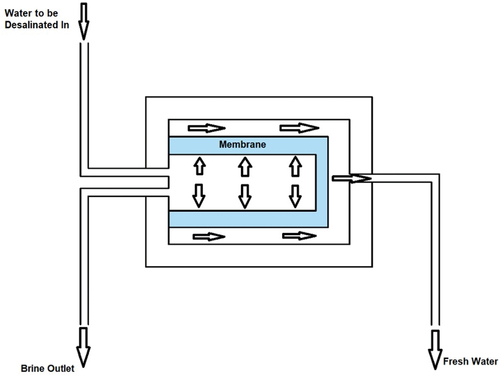
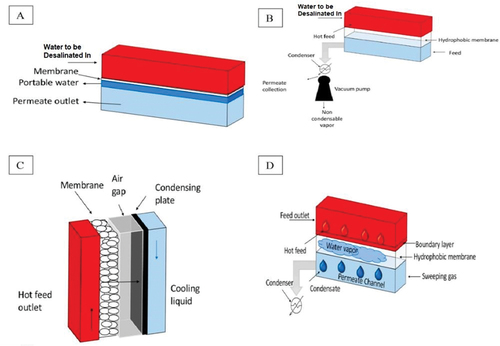
3.2.3. Membrane desalination technique (MDT)
MD is a heat-driven membrane-based technique in which vapour pressure is used as a driving force. The difference in temperature established between the two sides of the membrane, shown in , creates vapour pressure. The operational temperature of the system ranges between 30 and 80°C. The main component of the system is a hydrophobic microporous membrane that separates the vapour from the liquid by allowing the water vapour to pass and rejecting the flow of liquid molecules. This technique produces highly purified fresh water by preventing frequent fouling interruptions (Dow et al., Citation2016; Thomas et al., Citation2017). There are four possible configurations of the MD system (Curto et al., Citation2021; Khan & Al-Ghouti, Citation2021), as shown in :
Direct contact membrane distillation (DCMD): the hydrophobic membrane is in direct contact with two solutions. Because of the difference in pressure between the two solutions, the vapour produced on the surface of the hot solution goes inside the cold solution through the membrane.
Vacuum membrane distillation (VMD): this technique relies on the vacuum produced by a pump instead of the air gap.
Air gap membrane distillation (AGMD): a layer of air is added between the cold solution and the membrane to reduce the expenditure of thermal energy. The thermal resistance between the two fluids is increased by increasing the air gap, which obstructs the mass flow through the membrane. The condensation is externally realised by the distillation unit.
Sweeping gas membrane distillation (SGMD): a hydrophobic membrane is used to separate the hot solution from a sweep gas. The thermal efficiency of this technique is high, and the sweeping gas enhances the mass transfer effect.
Figure 11. Illustration of the MD desalination technique, using (A) direct contact, (B) vacuum, (C) air gap, and (D) sweeping gas (Chandrashekara & Yadav, Citation2017).
3.2.4. Nanofiltration (NF) desalination technique
NF is a pressure-driven membrane desalination technique that is often used for the separation of divalent and monovalent cations from the saline water. The NF membranes, shown in , have a pore size of around 0.2–2.0 nm, and require an operating pressure of 70–200 psi. The technique is claimed to be just as effective as RO; however, it is less expensive and more energy efficient (Silva et al., Citation2011). The saline water feed is pumped into the NF membrane system for the removal of the suspended solids. The operation pressure is kept constant, and the produced product water (permeate) and concentrate from the NF membranes are collected, stored in separate tanks, and distributed by distribution pumps (Evans & Miller, Citation2002).
Figure 12. Illustration of the NF desalination technique.
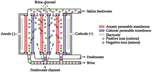
3.2.5. Electrodialysis desalination (EDD) technique
EDD is an electrochemical desalination technique that uses a combination of a generated electric field and semipermeable membranes to remove the dissolved ions from the saline water. Ionic transportation for electrodialysis depends on the concentration of ionic species and the properties of the membrane material. This technique requires less cleaning and regeneration of chemicals because it does not operate by water pressure, which reduces the formation of the fouling layer (Ismail et al., Citation2019). The dissolved salts are separated from the feed of the saline feedwater () in brine channels. When the saline water feed flows, the positive salt ions pass through the cation-semipermeable membrane towards negative electrodes, and the negative salt ions move through the anion-semipermeable membrane towards the positive electrode. The EDD technique recovers more fresh water and produces less brine compared to other filtration desalination techniques. The energy required to separate the ionic substances in the membrane is the direct current. The energy used is directly proportional to the quantity of the removed salts. As a mechanism to clean and preserve the condition of the EDD systems, the ion flow direction is frequently reversed by reversing the polarity of the electric current in the order of the system. This process is called electrodialysis reversal (EDR; Ullah & Rasul, Citation2019; Younos & Tulou, Citation2009).
Figure 13. Illustration of the ED desalination technique (Curto et al., Citation2021).
3.2.6. Ion-exchange resin (IER) desalination technique
IER involves a variety of organic compounds that are chemically treated to react with the solution ions. The IER desalination technique is classified according to its function into four groups, typically a strongly basic group, a weakly basic group, a strongly acidic group, and a weakly acidic group. The saline water flows firstly through the weakly and strongly acid resins, as shown in . Thus, the salty water’s acidity is increased. A degasser is then used; carbon dioxide is produced by the reaction between the bicarbonates in the saline water and hydrogen ions. After that, the saline water flows through the weakly and strongly basic resins, which reduces the acidity of the saline water. A mix of acid and base (an amphoteric resin) is added to complete the removal of the ions. During the process, the resins are progressively saturated by the ion exchange. Therefore, regeneration is frequently required to restore the resins. The regeneration process uses NaOH and NH4OH as base solutions for the basic resins, and H2SO4 and HCl as acid solutions for the acidic resins (Curto et al., Citation2021; Ullah & Rasul, Citation2019).
Figure 14. Illustration of the IER desalination technique.
3.3. Crystallisation desalination techniques
3.3.1. Hydration (HY) desalination technique
The HY desalination method is a phase-change-based process in which the saline water is converted into solid hydrate by removing the dissolved solids from the liquid phase. This technique requires a hydrate former such as salty water mixed with gas. This mix is then separated using hydrate formation. The heat exchanger removes the heat content of the saline water feed before it enters the reactor, as shown in . The gas chamber supplies the reactor with a makeup gas cylinder that is provided to remove the gas lost during process flow. The saline water feed and the gas in the reactor are thoroughly mixed with the help of a stirrer to form a gas hydrate by making an appropriate bonding interface between the saline water feed and gas molecules at suitable temperature and pressure conditions. For the given gas hydrate system, high-pressure and low-temperature conditions are maintained in the reactor. After the formation of the hydrate slurry, a pump moves the hydrate slurry to the crystalliser. The hydrate slurry is transformed into a crystalline solid structure along with the concentrated brine. The concentrated brine is drained from the crystalliser while the crystalline solid structure of the gas hydrate is moved to a decomposer in which the gas hydrate is decomposed again into water and gas, by heating it. After that, the gas flows into the gas storage tank and the remaining fresh water is collected at the bottom of the decomposer (Curto et al., Citation2021).
Figure 15. Illustration of the HY desalination technique.
3.3.2. Secondary refrigerant freezing (SRF) desalination technique
SRF is a desalination technique based on a liquid–solid phase transition, in which the saline water is contacted with an immiscible refrigerant (butane, ), and ice crystals are formed by butane evaporation. The refrigerant must be insoluble in water. The butane is distributed in the saline water feed by spraying it in the freezing chamber, where the butane is converted into vapour as the pressure of the freezing chamber remains low. Heat is removed from the saline water and transferred to the ice. The ice slurry is then transported to the separation unit by a pump, in which the ice is removed from the saline water and the temperature reaches the melting unit. The temperature and pressure of butane vapour are increased by the primary compressor in the freezing chamber. The butane vapour passes through the melting unit to melt the washed ice. As a result of the heat exchange between the butane and the ice, the ice is melted while the butane is condensed. The mixture is then transferred to a butane separator, in which the butane is separated and compressed again by a secondary compressor. The butane vapour is condensed and converted to liquid before entering the freezing chamber to be recycled. The product water is divided into two parts: a small amount that is moved to the separation unit, and a large amount that is moved to the heat exchanger for pre-cooling the incoming saline water feed (Tlili et al., Citation2019).
Figure 16. Illustration of the SRF desalination technique.
4. Applications of desalination techniques
Desalination plants around the world use more than 200 million kWh of power every day, with energy consumption accounting for about 55% of the total cost of operation and maintenance (Sharaf Eldean & Soliman, Citation2017). The extensive growth of saline water desalination capacity at present is occurring not only because of increased freshwater demands but also due to the significant reduction in the cost of desalination. This is the result of notable technological improvements that have made desalinated water more cost-effective compared to other water sources (Ahmad, Citation2012; Feria-Díaz et al., Citation2021). There are many plants worldwide that desalinate high-salinity produced water using any of the techniques discussed in section 3. A summary of some of the major applications of different desalination technologies for produced water desalination is provided in .
Table 3. Desalination techniques used for produced water desalination.
5. Conclusion
This research describes the different desalination techniques that can be used to produce fresh water from high-salinity seawater and produced water. The techniques were grouped into three broad categories based on their method of operation. For each desalination method, an illustration, a description of the process, and the main advantages and limitations were discussed. Based on the review, it was found that mechanical vapour compression, membrane distillation, and forward and reverse osmosis techniques are common desalination technologies used to desalinate produced water. The process for selecting a produced water desalination technique depends on many factors such as produced water chemistry, space availability, cost-effectiveness, reuse, and discharge methods. Solar-powered desalination methods show a very high potential for low-cost freshwater production, especially in isolated regions.
Nomenclature
| AGMD | = | air gap membrane distillation |
| BBW | = | boiler blowdown |
| BFW | = | boiler feed water |
| DCMD | = | direct contact membrane distillation |
| ED | = | electrodialysis |
| EOR/ECBM | = | enhanced oil recovery/enhanced coalbed methane |
| FO | = | forward osmosis |
| FPW | = | flowback and produced water |
| HCl | = | hydrochloric acid |
| HDH | = | humidification–dehumidification |
| H2SO4 | = | sulphuric acid |
| HY | = | hydration |
| IXR | = | ion-exchange resins |
| MD | = | membrane distillation |
| MED | = | multi-effect distillation |
| MSF | = | multi-stage flash |
| MVC | = | mechanical vapor compression |
| NaOH | = | sodium hydroxide |
| NH4OH | = | ammonium hydroxide |
| NF | = | nanofiltration |
| RO | = | reverse osmosis |
| RR | = | recovery ratio |
| SC | = | solar chimney |
| SGMD | = | sweeping gas membrane distillation |
| SRF | = | secondary refrigerant freezing |
| SSD | = | solar still desalination |
| TVC | = | thermal vapor compression |
| UF | = | ultrafiltration |
| VMD | = | vacuum membrane distillation |
| WLS | = | warm lime softener |
Disclosure statement
No potential conflict of interest was reported by the authors.
Additional information
Funding
References
- Abbas, A. J., Gzar, H. A., & Rahi, M. N. (2021). Oilfield-produced water characteristics and treatment technologies: A mini review. IOP Conference Series: Materials Science and Engineering, 1058(1), 1. https://doi.org/10.1088/1757-899X/1058/1/012063
- Abdel-Aal, H. K. (1998). Surface petroleum operations. Saudi Publishing & Distributing House.
- Abdel-Aal, H. K., Aggour, M., & Fahim, M. A. (2016). Petroleum and gas field processing (2nd ed.). Taylor & Francis Group.
- Abdel-Aal, H. K., & Shaikh, A. A. (1977). Desalting of oil using multiple orifice mixers: An empirical correlation for the water of dilution [Paper presentation]. Third Iranian Congress of Chemical Engineering, Iran.
- Abdunnabi, M., Belgasim, B., & Ramadan, A. (2021). Review on solar thermal desalination in Libya. The Journal of Solar Energy and Sustainability Development, 7(3). https://doi.org/10.51646/jsesd.v7i3.77
- Ahmad, M. M. (2012). Assessment of freezing desalination technologies. http://cronfa.swan.ac.uk/Record/cronfa42635
- Al-Karaghouli, A., & Kazmerski, L. L. (2013). Energy consumption and water production cost of conventional and renewable-energy-powered desalination processes. Renewable and Sustainable Energy Reviews, 24, 343–15. https://doi.org/10.1016/j.rser.2012.12.064
- Arnold, K., & Stewart, M. (2008). Surface production operations – Design of oil handling systems and facilities (3rd ed.). Elsevier Inc.
- Bahar, R., Hawlader, M. N. A., & Woei, L. S. (2004). Performance evaluation of a mechanical vapor compression desalination system. Desalination, 166(1–3), 123–127. https://doi.org/10.1016/j.desal.2004.06.066
- Chandrashekara, M., & Yadav, A. (2017). Water desalination system using solar heat: A review. Renewable and Sustainable Energy Reviews, 67, 1308–1330. https://doi.org/10.1016/j.rser.2016.08.058
- Compain, P. (2012). Solar energy for water desalination. Procedia Engineering, 46, 220–227. https://doi.org/10.1016/j.proeng.2012.09.468
- Curto, D., Franzitta, V., & Guercio, A. (2021). A review of the water desalination technologies. Applied Science, 11(2), 1–36. https://doi.org/10.3390/app11020670
- Deniz, E. (2012). An experimental and theoretical analysis of a vacuum tube solar collector-assisted solar distillation system. Energy Sources, Part A: Recovery, Utilization and Environmental Effects, 34(17), 1637–1645. https://doi.org/10.1080/15567036.2010.489104
- Desalination and Water Recycling. (2018). Mission 2017 global water security. MIT.
- Dow, N., Gray, S., Li, J.-D., Zhang, J., Ostarcevic, E., Liubinas, A., Atherton, P., Roeszler, G., Gibbs, A., & Duke, M. (2016). Pilot trial of membrane distillation driven by low grade waste heat: Membrane fouling and energy assessment. Desalination, 391, 30–42. https://doi.org/10.1016/j.desal.2016.01.023
- Evans, L., & Miller, J. (2002, January). Sweeping gas membrane desalination using commercial hydrophobic hollow fiber membranes. SAND2002-0138. https://doi.org/10.2172/793312
- Fasel, H. F., Meng, F., Shams, E., & Gross, A. (2013). CFD analysis for solar chimney power plants. Solar Energy, 98, 12–22. https://doi.org/10.1016/j.solener.2013.08.029
- Feria-Díaz, J. J., Correa-Mahecha, F., López-Méndez, M. C., Rodríguez-Miranda, J. P., & Barrera-Rojas, J.2021. Recent desalination technologies by hybridization and integration with reverse osmosis: A review. Water, 13, 1369. https://doi.org/10.3390/w13101369
- Fillo, J. P., Koraido, S. M., & Evans, J. M. (1992). Sources, characteristics, and management of produced waters from natural gas production and storage operations. Potable Water, 151–161. https://doi.org/10.1007/978-1-4615-2902-6_12
- Frankiewicz, T. (2001, January 17–19). Understanding the fundamentals of water treatment, the dirty dozen – 12 common causes of poor water quality [Paper presentation]. 11th Produced Water Seminar, Houston, TX.
- Frankiewicz, T. C., & Tussaneyakul, S. (1998, November 17-18). Removing hydrocarbons and heavy metals from produced water on the funan platform [Paper presentation]. API Produced Water Management Technical Forum and Exhibition, Lafayette, LA.
- Hisham, H. M. E., & El-Dessouky, T. (2002). Single effect evaporation vapor compression. In Fundamentals of salt water desalination (pp. 49–146). Elsevier. https://irancanftech.com/wp-content/uploads/2020/07/H.T.-El-Dessouky-H.M.-Ettouney-Fundamentals-of-Salt-Water-Desalination-Elsevier-Science-2002.pdf
- Ismail, A. F., Khulbe, K. C., & Matsuura, T. (2019). Hybrid system. In Reverse osmosis (pp. 143–162). Elsevier. https://doi.org/10.1016/C2016-0-00580-6
- Jitendra, R. S. P., Sangwai, S., Mekala, P., Mech, D., & Busch, M. (2013, December 4-6). Desalination of seawater using gas hydrate technology—Current status and future direction. In Proceeding of HYDRO 2013 international (pp. 434–440). IIT Madras. https://doi.org/10.1016/j.rser.2012.12.064
- Kasedde, H., Kirabira, J. B., Bäbler, M. U., Tilliander, A., & Jonsson, S. (2014). Characterization of brines and evaporites of Lake Katwe, Uganda. Journal of African Earth Sciences, 91, 55–65. https://doi.org/10.1016/j.jafrearsci.2013.12.004
- Katal, I. J. R., Shen, T. Y., Masudy-Panah, S., & Farahani, M. H. D. A. (2020). An overview on the treatment and management of the desalination brine solution. In Desalination - Challenges and opportunities (p. 13). Intech Open.
- Khan, M., & Al-Ghouti, M. A. (2021). DPSIR framework and sustainable approaches of brine management from seawater desalination plants in Qatar. Journal of Cleaner Production, 319(February), 128485. https://doi.org/10.1016/j.jclepro.2021.128485
- Khurshid, I., Hossain, M. M., Alraeesi, A., Fares, A., Albalushi, F., & Alhammadi, A. (2018). Desalination of produced water of Asab oil field Abu-Dhabi to enhance its oil recovery and water injectivity. Society of Petroleum Engineers - SPE International Conference and Exhibition on Health, Safety, Security, Environment, and Social Responsibility, 2018. https://doi.org/10.2118/190505-ms
- Liu, S., Dong, X., Ban, H., Wang, T., Pan, W., Yu, H., Guo, C., & Suo, C. (2009). Technology for confecting polymer solution with desalinated produced water. SPE Production and Operations, 24(1), 208–212. https://doi.org/10.2118/110237-pa
- Mabrook, B. (1994). Environmental impact of waste brine disposal of desalination plants, Red Sea, Egypt. Desalination, 97(1–3), 453–465. https://doi.org/10.1016/0011-9164(94)00108-1
- Minier-Matar, J., Hussain, A., Janson, A., & Adham, S. (2014, January). Treatment of produced water from unconventional resources by membrane distillation. In International press telecommunications council [IPTC] (Doha, Qatar, 1/19-22/2014) proceeding. https://doi.org/10.2523/17481-ms
- Mohammad, A. F., El-Naas, M. H., Al-Marzouqi, A. H., Suleiman, M. I., & Al Musharfy, M. (2019). Optimization of magnesium recovery from reject brine for reuse in desalination post-treatment. Journal of Water Process Engineering, 31(December 2018), 1–8. https://doi.org/10.1016/j.jwpe.2019.100810
- Mohammadesmaeili, F., Badr, M. K., Abbaszadegan, M., & Fox, P. (2010). Mineral recovery from inland reverse osmosis concentrate using isothermal evaporation. Water Reserch, 44(20), 6021–6030. https://doi.org/10.1016/j.watres.2010.07.070
- Muraleedaaran, S., Li, X., Li, L., & Lee, R. (2009). Is reverse osmosis effective for produced water purification? Viability and economic analysis. In SPE west regional meeting 2009 - Proceeding (pp. 1–16). SPE -Society of Petroleum Engineers. https://doi.org/10.2118/115952-ms
- Pérez-González, A., Urtiaga, A. M., Ibáñez, R., & Ortiz, I. (2012). State of the art and review on the treatment technologies of water reverse osmosis concentrates. Water Reserch, 46(2), 267–283. https://doi.org/10.1016/j.watres.2011.10.046
- Poblete, R., Salihoglu, G., & Kamil Salihoglu, N. (2016). Investigation of the factors influencing the efficiency of a solar still combined with a solar collector. Desalination and Water Treatment, 57(60), 29082–29091. https://doi.org/10.1080/19443994.2016.1202872
- Pramanik, B. K., Shu, L., & Jegatheesan, V. (2017). A review of the management and treatment of brine solutions. Environmental Science: Water Research & Technology, 3(4), 625–658. https://doi.org/10.1039/c6ew00339g
- Sadrzadeh, M., Pernitsky, D., & McGregor, M. (2012). Nanofiltration for the treatment of oil sands-produced water. Intech Open. https://doi.org/10.5772/intechopen.74086
- Sánchez, A. S., & Matos, Â. P. (2018). Desalination concentrate management and valorization methods. Elsevier Inc. https://doi.org/10.1016/B978-0-12-809240-8.00009-5
- Shaffer, D. L., Arias Chavez, L. H., Ben-Sasson, M., Castrillo, S. R., Yip, N. Y., & Elimelech, M. (2013). Desalination and reuse of high-salinity shale gas produced water: Drivers, technologies, and future directions. Environmental Science & Technology, 47(17), 9569–9583. https://doi.org/10.1021/es401966e
- Shang, W., Tiraferri, A., He, Q., Li, N., Chang, H., Liu, C., & Liu, B. (2019). Reuse of shale gas flowback and produced water: Effects of coagulation and adsorption on ultrafiltration, reverse osmosis combined process. Science of the Total Environment, 689, 47–56. https://doi.org/10.1016/j.scitotenv.2019.06.365
- Sharaf Eldean, M. A., & Soliman, A. M. (2017). A novel study of using oil refinery plants waste gases for thermaldesalination and electric power generation: Energy, exergy & cost evaluations. Applied Energy, 195, 453–477. https://doi.org/10.1016/j.apenergy.2017.03.052
- Sharon, H., & Reddy, K. S. (2015). A review of solar energy driven desalination technologies. Renewable and Sustainable Energy Reviews, 41, 1080–1118. https://doi.org/10.1016/j.rser.2014.09.002
- Silva, V., Geraldes, V., Brites Alves, A. M., Palacio, L., Prádanos, P., & Hernández, A. (2011). Multi-ionic nanofiltration of highly concentrated salt mixtures in the seawater range. Desalination, 277(1–3), 29–39. https://doi.org/10.1016/j.desal.2011.03.088
- Sola, I., Zarzo, D., & Sánchez-Lizaso, J. L. (2019). Evaluating environmental requirements for the management of brine discharges in Spain. Desalination, 471(June), 114132. https://doi.org/10.1016/j.desal.2019.114132
- Sparrow, B., Ebsary, A., Mandel, D., & Man, M. (2018). An advanced electrochemical system for EOR produced water desalination and reduced polymer consumption. In Proceedings of the SPE improved oil recovery (Vol. 2018-April, pp. 0–4). SPE -Society of Petroleum Engineers. https://doi.org/10.2118/190272-ms
- Talaeipour, M., Nouri, J., Hassani, A. H., & Mahvi, A. H. (2017). An investigation of desalination by nanofiltration, reverse osmosis and integrated (hybrid NF/RO) membranes employed in brackish water treatment. Journal of Environmental Health Science & Engineering, 15(1). https://doi.org/10.1186/s40201-017-0279-x
- Thomas, N., Mavukkandy, M. O., Loutatidou, S., & Arafat, H. A. (2017). Membrane distillation research & implementation: Lessons from the past five decades. Separation and Purification Technolog, 189(July), 108–127. https://doi.org/10.1016/j.seppur.2017.07.069
- Tlili, I., Osman, M., Barhoumi, E. M., & Sayed, K. (2019). Performance enhancement of a humidification–dehumidification desalination system: A thermodynamic investigation. Journal of Thermal Analysis and Calorimetry, 140(12). https://doi.org/10.1007/s10973-019-08775-8
- Ullah, I., & Rasul, M. G. (2019). Recent developments in solar thermal desalination technologies: A review. Energies, 12(1). https://doi.org/10.3390/en12010119
- United Nations. (2017). Factsheet: People and oceans. Factsheet: People and Oceans, 549, 40–42.
- Václavíková, N., Zich, L., & Doležel, M. (2017). Pilot module for electrodialysis-metathesis protected against shunt currents. Desalination and Water Treatment, 75(May 2016), 320–324. https://doi.org/10.5004/dwt.2017.20446
- Veil, J. A., Puder, M. G., Elcock, D., & Redweik, R. J., Jr. (2004). A white paper describing produced water from production of crude oil, natural gas, and cola bed methane. U.S. Department of Energy, National Energy Technology Lab.
- Wafi, M. K., Hussain, N., El-Sharief Abdalla, O., Al-Far, M. D., Al-Hajaj, N. A., & Alzonnikah, K. F. (2019). Nanofiltration as a cost-saving desalination process. SN Applied Sciences, 1(7), 1–9. https://doi.org/10.1007/s42452-019-0775-y
- Webb, C. (2019). Desalination of oilfield produced water using electrocoagulation and reverse osmosis. SPE Western Regional Meeting Procedure, 2019. https://doi.org/10.2118/195363-ms
- Webb, C., North, C., Exploration, A., Nagghappan, L., & Water, V. N. A. (2009). Desalination of oilfield-produced water at the san ardo water reclamation facility, CA. In SPE international 121520, western regional meeting held in San Jose (pp. 1–21). https://www.onepetro.org/conference-paper/SPE-121520-MS
- Xu, T. (2005). Ion exchange membranes: State of their development and perspective. Journal of Membrane Science, 263(1–2), 1–29. https://doi.org/10.1016/j.memsci.2005.05.002
- Xu, N., Li, J., Wang, Y., Fang, C., Li, X., Wang, Y., Zhou, L., Zhu, B., Wu, Z., Zhu, S., & Zhu, J. 2019. A water lily– Inspired hierarchical design for stable and efficient solar evaporation of high-salinity brine. Science Advances, Applied Science and Engineering. https://doi.org/10.1126/sciadv.aaw7013
- Younos, T., & Tulou, K. E. (2009). Overview of desalination techniques. Journal of Contemporary Water Research & Education, 132(1), 3–10. https://doi.org/10.1111/j.1936-704x.2005.mp132001002.x
- Youssef, P. G., Al-Dadah, R. K., & Mahmoud, S. M. (2014). Comparative analysis of desalination technologies. Energy Procedia, 61, 2604–2607. https://doi.org/10.1016/j.egypro.2014.12.258
- Zhu, Z., Xu, Y., Luo, Y., Wang, W., & Chen, X. (2021). Porous evaporators with special wettability for low-grade heat-driven water desalination. Journal of Materials Chemistry A, 9(2), 702–726. https://doi.org/10.1039/D0TA09193F
- Zimerman, Z. (1994). Development of large capacity high efficiency mechanical vapor compression (MVC) units. Desalination, 96(1–3), 51–58. https://doi.org/10.1016/0011-9164(94)85156-5