MECHANICAL PROPERTIES
Artificial cells prepared by the methods described and suspended in an aqueous medium are usually spherical. Preliminary observations suggest the membrane thickness in 80μ nylon membrane artificial cells made by the standard procedure is about 200 Å. That this ultrathin membrane is extremely flexible is demonstrated when the artificial cells are ruptured by dissecting needles to remove the contents. The membrane left is extremely flexible and does not retain the original spherical shape.
The sphericity of the artificial cell membrane is due to the colloid osmostic pressure gradient generated by the enclosed protein. Thus, when spherical artificial cells are placed in a hypertonic solution, the outward movement of water results in the folding of the spherical membranes (). In addition, when spherical nylon membrane artificial cells of about 100μ diameter are forced under hydrostatic pressure to flow slowly through the narrow portion of a glass tube, the membrane is seen to fold (). After passing through the narrow portion of the tubing, the artificial cells gradually return to their spherical shape. The time course of the change makes it apparent that water is forced out of the artificial cells as they pass through the constriction and returns after the artificial cells have emerged. Another observation illustrating the flexibility of the artificial cell membrane is shown in . Here two large nylon membrane artificial cells (diameter about 1 mm) are suspended in silicone fluid and subjected to sheer stress and collision in a Couette flow situation. In it can be seen that artificial cells which are under sheer stress applied in opposite directions elongate in the line of sheer stress; and on collision, the membranes flatten at the point of contact.
Figure 15. Nylon membrane artificial cells shortly after being placed in hypertonic solution. (From Chang, 1964. Copyright 1964 by the American Association for the Advancement of Science.)
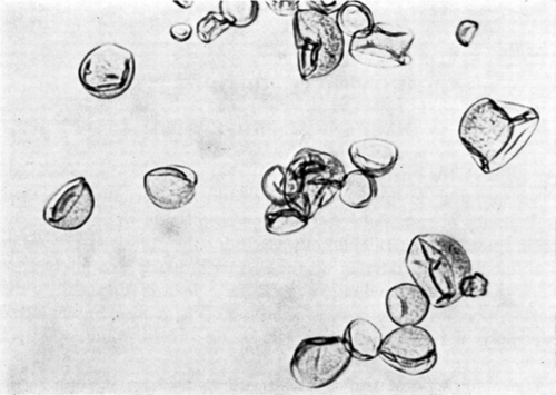
Figure 16. Deformability of a nylon membrane artificial cell. The artificial cell, about 100μ in diameter and suspended in saline, is moving from left to right along a tapering glass capillary and is subjected to a hydrostatic pressure gradient from left to right. Note flattening of upstream surface, bulging of downstream surface, longitudinal folding of membrane, and smaller volume of artificial cell as a result of filtration of fluid through downstream surface into capillary. (From Chang, 1965; Chang et al., 1966. Courtesy of the National Research Council of Canada.)
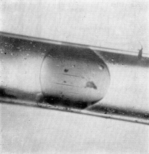
Figure 17. Deformability of nylon membrane artificial cells. Two artificial cells about 1 mm in diameter, suspended in silicone oil and placed in Couette flow apparatus. Left to right, zero flow; onset of Couette flow; collision; separation after collision; cessation of flow. (From Chang, 1965.)

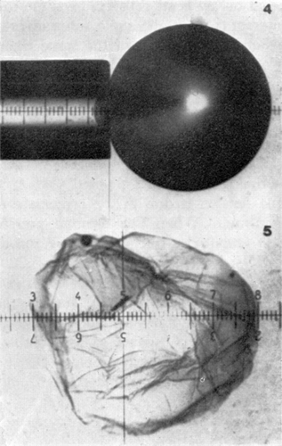
Jay and Edwards (1968) have used a cell elastometer to study more quantitatively the mechanical properties of nylon membrane artificial cells prepared by the standard procedure (Chang, 1964; Chang et al., 1966). Their cell elastometer is similar to that used for studying the mechanical properties of urchin egg membranes (Mitchison and Swann, 1954) and erythrocyte membranes (Rand and Burton, 1963). The apparatus () consists essentially of a micropipette (radius, Rp of 50μ to 260μ) connected to a mercury column which can be varied to adjust the pressure (P1) inside the micropipette. Microcapsules of radius Rc are suspended in an aqueous medium having a hydrostatic pressure of P2. The micropipette is then applied to the surface of an artificial cell, and by varying the negative pressure in the micropipette, a small tongue of membrane of length x can be drawn into the micropipette ( and ).
Figure 18. Schematic representation of cell elastometer. (From Jay and Edwards, 1968. Courtesy of the National Research Council of Canada.)
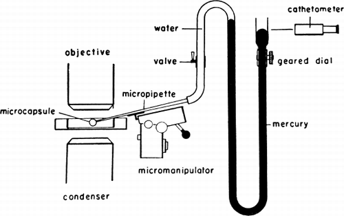
Figure 19. Schematic representation of artificial cell with a portion of the membrane drawn into the elastometer micropipette. Parameters involved are described in detail in text. (From Jay and Edwards, 1968. Courtesy of the National Research Council of Canada.)
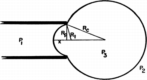
Figure 20. Upper, microphotograph of artificial cell with a portion of the membrane drawn into the elastometer micropipette (a much higher magnification was used in the experiments). Lower, a ruptured artificial cell showing the absence of any rigidity in the membrane. Spherical shape is maintained by the colloid osmotic pressure. (From Jay and Edwards, 1968. Courtesy of the National Research Council of Canada.)
A small negative pressure of 1 mm Hg can easily draw the whole artificial cell into the micropipette, if the artificial cell membranes are not under the tension of the osmotic pressure gradient. Thus the bending stress of the artificial cell membrane is negligible. On the other hand, when artificial cell membranes are under an osmotic pressure gradient, the hydrostatic pressure required is as follows. When the pressure difference P2−P1 is plotted against the length of the tongue of the microcapsule membrane (x) sucked into the micropipette, the characteristic curve is shown in . Initially, the relationship is linear, but with a further increase in the pressure difference (P2−P1), a point is reached when the slope of the curve suddenly decreases. Further increase in pressure beyond this point results in rupturing of the artificial cells. Using equation P2−P1=2T, the membrane tension (T) at which the slope of the curve suddenly decreases is 2520±20 dynes/cm. This same value is obtained for artificial cells of different diameters. The y-intercepts of these pressure deformation curves correspond to the pressure differences across the artificial cell membrane when the artificial cells are not deformed by the micropipettes. This is the internal pressure of the artificial cells (P3). Micropipettes of different radii (Rp) tested on artificial cells of the same radius (Rc) give the same y-intercepts, thus the same internal pressures. On the other hand, when micropipettes of the same radius are used on artificial cells of different radii, different values of internal pressures (y-intercepts) are obtained (). When internal pressures are plotted against the reciprocals of the artificial cell radii, a straight line relationship is obtained, showing that the internal pressure is in inverse relationship to the diameter. From the equation P3−P2=1Tc/Rc, a membrane tension of 1840 dynes/cm is obtained. It should be noted that in these tests the high membrane tension is due to the osmotic pressure gradient across the membrane. When this osmotic pressure gradient is removed, e.g. in crenated artificial cells, this tension is no longer present.
Figure 21. Pressure-deformation curves for various sizes of artificial cells. Rp=105μ. Note the abrupt change in slope at high pressures. (From Jay and Edwards, 1968. Courtesy of the National Research Council of Canada.)
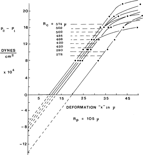
In summary, Jay and Edwards show that the membranes of artificial cells prepared from different batches having a range of diameters all appear to have the same stiffness, the same tension, and the same critical tension—a remarkable uniformity in the mechanical properties of artificial cells. Despite the ultrathin membrane, it can withstand a membrane tension of up to 2520±20 dynes/cm.
OPTICAL PROPERTIES
Anderson and Selkey (1967) studied the light transmission and scattering properties of 40μ diameter nylon membrane artificial cells prepared in this laboratory (Chang, 1964; Chang et al., 1966). The optical density was measured in the integrating sphere at four wave lengths, 5400 Å, 5600 Å, 5700 Å, and 5800 Å, at a sample depth of 0.071 cm. The hematocrit of the artificial cells was varied from 4% to 44%.
The optical density was plotted against the percentage hematocrit values. As in the case of erythrocytes, the experimental results obtained for artificial cells agreed well with values calculated theoretically.
ELECTRICAL PROPERTIES
We have used a cell electrophoresis apparatus to study the surface properties of artificial cells with different membrane compositions (Chang, 1965; Chang et al., 1967b). In one set of experiments, it has been observed that whereas the electrophoretic mobilites for erythrocytes or artificial cells with sulfonated nylon membranes are 0.85μ±0.08μ/sec/volt/cm and 1.18μ±0.24μ/sec/volt/cm respectively, artificial cells with nylon membranes do not have any measurable net surface charge. In another set of experiments, the electrophoretic mobilities of dog erythrocytes, of artificial cells with collodion membranes, and of artificial cells with heparin-complex (BHC) collodion membranes are found to be 0.93μ±19μ/sec/volt/cm, 0.93μ±0.06μ/sec/volt/cm, and 0.55μ±0.11μ/sec/volt/cm, respectively, when measured in a phosphate buffer solution. The addition of dog plasma to the buffer solution (1/1000) does not significantly alter the electrophoretic mobility of the dog erythrocytes and of the artificial cells with BHC-collodion membranes (1.10μ±0.10μ and 0.53μ±0.11μ/sec/volt/cm respectively), but lowers the electrophoretic mobility of the artificial cells with collodion membranes to below the measurable limit. Albumin has been incorporated into the microcapsule membranes (Chang, 1969e; Shiba et al., 1970). The electrophoretic mobility of artificial cells with a membrane component containing albumin shows a negative surface charge (Shiba et al., 1970).
Using 3M-KC1 microelectrodes, Jay and Burton (1969) have investigated the potential differences across the membranes of human red blood cells and artificial cells. The nylon membrane artificial cells (10μ–500μ diameter) containing hemolysate are prepared as described (Chang, 1964; Chang et al., 1966). In the case of human red blood cells, the potential difference across the cell membranes is −8.0±0.21 mV (SEM), the inside being negative with respect to the outside. When the microelectrode penetrates the artificial cell membrane, a sharp spike is observed. This is followed immediately by a deflection which reaches a maximal negative value of −2 to −4 mV by about five seconds. This then decays in less than ten seconds to a constant value of −0.52±0.02 mV (SEM) (35 measurements). This value remains unchanged until the microelectrode is retracted. As soon as the microelectrode is retracted, the deflection returns to the base line. Jay and Burton suggest that the potential difference of 0.52±0.02 mV (SEM) is due to Donnan equilibrium as a result of the presence of the nondiffusible hemoglobin in the nylon membrane artificial cells.
In further studies, Jay and Sivertz (1969) measure the electrical resistance of membranes of artificial cells (80μ–350μ diameter) prepared as described (Chang, 1964; Chang et al., 1966). A suction-pipette holds the artificial cell for impalement by the 3M-KCl microelectrodes having a tip diameter of 0.5μ. The larger end of the microelectrode is sealed in a 3M-KCl filled micropipette holder to prevent entry of fluid from the artificial cells. Having measured the electrode resistance, Re, they impaled the artificial cell membranes and obtained the total resistance of the electrode and nylon membranes, Re+Rm. On withdrawal of the microelectrode, the electrode resistance was checked again. The membrane resistance, Rm, for artificial cells of different diameters was plotted against the reciprocal of the membrane area of each artificial cell, 1/A. A straight line passing through the origin was obtained. Thus the relationship follows the equation Rm=px/A (p is the resistivity of the membrane and x is the thickness of the membrane, and px is the specific resistivity of the membrane). The specific resistivity was found to be 5.6×10³ ohm-cm2. Using the value of 200 Å for the membrane thickness (Chang et al., 1966), Jay and Sivertz calculated that the resistivity, p, was 3×10 ohm-cm.
Mueller and Rudin (1968) used an internal microelectrode technique to study lipid membrane artificial cells containing red blood cell hemolysate. They found that these membranes have the same electrical properties as the planar bilayer lipid membranes. Pagano and Thompson (1968) studied the transmembrane electrical properties of spherical bilayer membranes several millimeters in diameter. They found that the specific resistance was 3.5–6.8×10⁶ ohm-cm2, capacitance was 0.5μF/cm2, and voltage breakdown potential was 200 mV.
GENERAL PERMEABILITY CHARACTERISTICS
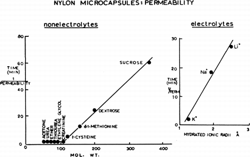
Artificial cells suspended in distilled water present a smooth, spherical surface; but artificial cells placed in a hypertonic solution quickly shrink and show folding of their membranes. This is very striking in the case of nylon membrane artificial cells (), but much less obvious in the case of collodion membrane artificial cells, which have thicker membranes. The shrinkage and the folding are clearly analogous to the phenomena of crenation in erythrocytes and plasmolysis in plant cells. As a result of the osmotic pressure gradient, water is withdrawn from the artificial cells. The shrinkage in exceeds 50 percent of the initial volume as indicated by centrifugation of the suspension in a hematocrit tube. When artificial cells are suspended in a hypertonic solution containing a solute of large molecular or ionic radius, crenation is long-lasting, since penetration of the artificial cells by the solute is slow. But when this solute is of smaller molecular or ionic radius, penetration of the solute is faster and crenation is more quickly reversible, the artificial cells swelling to recover their original form. As would be expected, the duration of crenation is related to the artificial cell diameter, the smaller artificial cells recovering their spherical form more quickly because of the more rapid equilibration of solute across the membrane. There is a satisfactory correlation with molecular weight in the case of the nonelectrolytes tested, and a similar correlation with the hydrated ionic radii in the case of the three alkali metals—Li+, K+ and Na+—tested as the chlorides (). Similar studies show that the ionic properties of the carboxyl and amino groups in the nylon membrane of the artificial cells are such that the membrane can become anion-selective or cation-selective by changes in the environmental pH. The permeability characteristics of the artificial cell membranes are further characterized by the more detailed studies discussed in the following sections.
EQUIVALENT PORE RADIUS
According to Van Hoff's equation, a solution with a solute concentration of C can exert an osmotic pressure of πt where πt=RTC. This equation only holds when the osmotic pressure is measured across a membrane which is permeable to water but not to the solute. For a membrane which is permeable to both the water and the solute, the effective osmotic pressure (πe) is less than the theoretical osmotic pressure (πt) calculated from this equation. The ratio of the effective osmotic pressure to the theoretical osmotic pressure is the reflective coefficient (Staverman, 1957). The reflective coefficient is unity for an impermeant solute, but is less than unity and approaches zero the more permeant the solute. The reflective coefficient is thus a quantitative expression of the permeability characteristics of a membrane, and so much so that experiments demonstrate that the equivalent pore radius of biological membranes can be calculated from reflective coefficients (Solomon, 1961, 1969). We have used this concept to measure the equivalent pore radius of artificial cell membranes (Chang, 1965; Chang and Poznansky, 1968c).
Nylon membrane artificial cells of 270μ±87μ diameter prepared by the standard method are dialyzed overnight in 100 volumes of distilled water to remove dialyzable contents. Immediately before use, the artificial cells are washed three times with 10 volumes of distilled water and suspended in 2 volumes of distilled water and kept at 37°C±0.35 degree. At zero time, 0.15 ml of the suspension is added to 1 ml of different test solutions kept at 37°C. A microphotograph is taken at exactly 60 seconds (stopwatch) after the addition of the artificial cells to the test solutions. Observations show that well-prepared nylon membrane artificial cells suspended in water have a smooth membrane and are perfectly spherical, but when they are suspended in solutions of increasing concentrations, folding of the membranes can be observed, somewhat analogous to crenation in erythrocytes or plasmolysis in plant cells. At first this folding occurs in a small proportion of the artificial cells, but as the solute concentration is progressively increased, both the proportion of artificial cells with folded membranes and the degree of folding of the membranes increase. All the artificial cells on each microphotograph can be classified as collapsed or not collapsed, collapsed artificial cells being defined here as the presence of any observable foldings in the membrane. At least 100 artificial cells are counted for each concentration of solution. Control studies show that counts of the percentage of collapsed artificial cells on the same microphotograph presented to the observer at different times without his being aware give a standard deviation of ±1.13% in five trials. Once collapsed, the artificial cells remain so for at least one minute when four test solutes are used at the stated concentrations. It should be noted at this point that although collapsed artificial cells gradually return to their original spherical shape if the solute can cross the membranes, the recovery of the folded membranes is much slower than would be expected from permeability studies of the undeformed artificial cells. In the folded form, the membranes are no longer stretched by the tension created by the colloid osmotic pressure. The permeability of the folded membranes is thus much less than those of the spherical forms. This makes it possible for the present study to be carried out without a rapid mixing technique.
With glucose as the standard solute, all points fit well on a probit graph by a straight line (). The explanation for this relationship is as follows. The diameters of artificial cells prepared follow a bell-shaped distribution curve with a standard deviation of ±30%. If a curve is made relating 1/R (R=radius of artificial cells) and the percentage of artificial cells with diameters of more than a given radius, the results fit well into a straight line when plotted on a probit graph. The slope corresponds quite well with the slope of the relationship between percentage of collapsed artificial cells and concentration of glucose solution. Since nylon membrane artificial cells have internal pressures which are inversely proportional to their radii (Jay and Edwards, 1968), the smaller the artificial cells, the greater is the internal hydrostatic pressure, and thus the greater is the external effective osmotic pressure required to collapse the artificial cells (Chang, 1965; Chang and Poznansky, 1968c). The artificial cells are thus microscopic membrane osmometers, each having an internal hydrostatic pressure inversely proportional to its diameter, and each can be collapsed only if the effective external osmotic pressure exceeds that of the internal hydrostatic pressure. The percentage of artificial cells collapsed at a given solute concentration depends on the percentage of artificial cells having an internal pressure which is less than the effective osmotic pressure of the suspending medium. In other words, solutions having the same effective osmotic pressure should cause the same percentage of artificial cells to collapse.
Figure 23. Upper, percentage of collapsed nylon membrane artificial cells as a function of glucose concentration in the medium. Abscissae: concentration of glucose in suspending medium. Ordinates (plotted on probit scale): percentage of artificial cells found to be collapsed in the glucose medium. Lower, percentage of collapsed artificial cells in nonelectrolyte solutions plotted on probit scale. •=sucrose; ▴=glucose; ○=propylene glycol; ▾=ethylene glycol. (From Chang, 1965; Chang and Poznansky, 1968. Courtesy of Interscience Publishers, New York.)
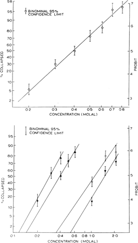
The results obtained from different test solutes are shown in . The extrapolation to the x-axis is taken as the threshold concentration. The results obtained are summarized in . Each threshold concentration represents the statistically obtained concentration of a given solute which just fails to cause any collapse of artificial cells. As discussed earlier, solutions having the same effective osmotic pressure cause the same percentage of artificial cells to collapse. These statistically obtained threshold concentrations of the four test solutions, sucrose (Cs), dextrose (Cd), ethylene glycol (Ce) and propylene glycol (CP), thus represent concentrations of these solutes which give the same effective osmotic pressure (πe).
Since πe=σRTC, and since the effective osmotic presures (πe) are the same for the four test solutes, sucrose (s), dextrose (d), ethylene glycol (e), and propylene glycol (p), at their threshold concentrations (C), it follows thatThe reflection coefficient is related to the equivalent pore radius (r) of a membrane by the following equation:
where a is the radius of the solute in question and aw the radius of water. Using a modification of Solomon's principle (1961), the equivalent pore radius of artificial cells is estimated from the results obtained in the following way.
From equation 1 six ratios (σs/σd=Cd/Cs; σs/σe=Ce/Cs; σs/σP=CP/Cs; σd/σs=Cs/Cd; σd/σe=Ce/Cd; σd/σP=CP/Cd and σe/σP=CP/Ce) can be obtained. From equation 2, these ratios can be related to the equivalent pore radius as follows:where x and y are two nonelectrolytes with known radii ax and ay.
Theoretical values for each ratio (Cx/Cy) at different equivalent pore radii can be calculated from equation 3 and plotted (). This way, six theoretical curves are obtained, but of these, two curves (Ce/CP and Cd/Cs) give no useful information because the slopes of the lines are too flat. For the remaining four pairs, the observed ratios obtained experimentally fall on the curves corresponding to an equivalent pore radius of between 17 Å and 19 Å. Perhaps the best single estimate for the equivalent pore radius is 18 Å.
Figure 24. Analysis of equivalent pore radius for nylon membrane artificial cells prepared by the standard procedure. (For explanation see text.) Each of the 4 theoretical curves relates the ratio of reflection coefficients for a given pair of solutes to equivalent pore radii from 0 to 30 Å. The plotted points (mean±standard deviation) are experimentally determined values for 4 solute pairs. (From Chang and Poznansky, 1968. Courtesy of Interscience Publishers, New York.)
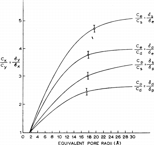
The equivalent pore radius of the artificial cells prepared by the standard procedure is optimal in serving as a dialyzing membrane which is impermeable to proteins but extremely permeable to small biological molecules. If required, the equivalent pore radius can be varied by varying the time of reaction in the case of nylon membrane artificial cells. Other modifications include the use of membrane materials with different permeability characteristics.
PERMEABILITY CONSTANTS
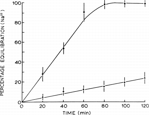
Because of the rapid equilibration of permeant solutes across artificial cells, a rapid mixing and sampling apparatus is required to study the permeability constants of the enclosing membranes (Chang and Poznansky, 1968c). Nylon membrane artificial cells with diameters of 210.9μ±75μ SD are prepared by the method described at a jumbo magnetic stirrer speed setting of 2.5 and Span 85 concentration of 1 percent. Collodion membrane artificial cells with diameters of 214μ±18μ SD are prepared as described at a jumbo magnetic stirrer speed setting of 2.5, but without the use of Span 85. The artificial cells are finally suspended in a 300mM sodium chloride solution and allowed to stand for 12 hours while the sodium chloride equilibrates completely across the artificial cells. In these experiments, final suspensions contain 110,000 artificial cells per milliliter. A higher concentration of artificial cells is less convenient for rapid mixing and sampling. The results obtained are as shown for nylon membrane artificial cells ( and ). Similar results are obtained for collodion membrane artificial cells. In the case of polyurethane membranes, the permeability constants (10−5 cm/min) are 0.32 for CsCl, 0.30 for NaCl, 0.25 for LiCl, 0.31 for NaBr, 0.28 for Na2SO4, 0.20 for Na2CrO4 (Shigeri and Kondo, 1969).
Figure 25. Upper, rapid mixing and sampling apparatus used in the determination of permeability constants. Rotating arm (1) opens valve (1) to air pressure and triggers the rapid injection of artificial cell suspension and test solution through the mixing chamber into a collecting beaker. After a predetermined interval, rotaring arm (2) of kymograph triggers the sampling syringe to aspirate an aliquot of artificial cell free supernatant through the filter. Lower, permeability constants, example of results obtained. Rate of entry of solute measured as the rate of decrease of radioactivity in the suspending medium. Concentration of artificial cells (diameter 210.9μ±75.0μ) in the suspension after the addition of an equal volume of the test solution is 55,000/ml. (From Chang and Poznansky, 1968. Courtesy of Interscience Publishers, New York.)
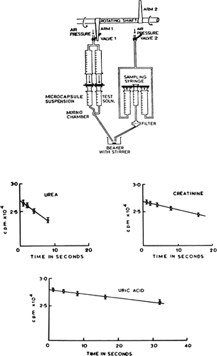
Table 1. Nylon Membrane Artificial Cells: Permeability Data
LIPID MEMBRANES
Spherical Lipid Bilayer Membranes
Mueller and Rudin (1968) combined their technique of planar bimolecular membrane formation (Mueller et al., 1962) with the technique for preparing artificial cells (Chang, 1964) to form “cellules” of about 90μ diameter. Each of these consists of red blood cell hemolysate enveloped in a spherical ultrathin lipid membrane which is 60 to 100 Å thick. When these cellules are exposed to a hypertonic sodium chloride solution, there is a reduction in size within 15 seconds. The reduction in size persists indefinitely, showing good permeability to water but very limited permeability to sodium chloride. Internal microelectrode studies show the same electrical properties as the planar bilayers.
Pagano and Thompson (1967) studied another form of spherical lipid bilayer membranes of much larger diameters of 4 mm. In preliminary studies they found that the water permeability coefficients are 10μ/sec; the specific resistance is 0.35–0.68 ohm-cm2; capacitance is about 0.5μF/cm2; breakdown potential is 200 mV. Thus the properties are very similar to those of the planar system. In further detailed studies Pagano and Thompson (1968) studied the isotopic fluxes of 22Na and 36Cl and found that the unidirectional fluxes MNa and MCl were respectively 0.39±0.02 and 90.2±0.8 pmoles/cm2/sec at 30°C. The chloride flux was also studied as a function of temperature, and the activation energy for chloride permeation across the bilayer was calculated to be 10.7±0.4 kcal/mole. Other studies were made by Pagano and Thompson to compare the experimental results of the sodium and chloride flux measurements with the theoretical values as calculated from the electrical parameters of the spherical bilayer membrane. It was found that while the sodium flux falls within the range of values calculated from the electrical data (0.0298–1.194 pmoles/cm2/ses); the chloride flux is of much greater magnitude than the theoretical value (0.061–0.245 pmoles/cm2/sec). In fact, the chloride flux is more than 300 times greater than the calculated value. The authors postulated that the chloride flux consists of an ionic component to account for the electrical parameters, and an exchange diffusion component. They then carried out experiments to examine MCl as a function of chloride ion concentration within the spherical bilayer. The chloride influx is very small when no chloride ion is in the interior aqueous phase. They found that the addition of 0.05M NaCl to the internal aqueous phase increases the observed chloride flux markedly. In addition, the chloride flux exhibits a saturation kinetic mechanism reaching a maximal rate by 0.1M NaCl internal concentration. All these observations have led the authors to propose that a carrier mechanism is present for chloride permeation acros the bilayer spherical membranes. Pagano and Thompson (1968) suggested the following as possible carriers: (1) sodium ion, (2) a small unknown molecule present in the membrane, (3) the phospholipid, or (4) a heavy metal phospholipid complex.
Lipid-Macromolecular Complex Membranes
The exact molecular organization of biological cell membranes is not known. However, that biological membranes are not composed of lipids alone is without dispute. Recently, Korn (1968) proposed a possible model in which he suggested that in the biosynthesis of biological cell membranes the protein unit of the membrane is formed first, followed by the addition of the lipid components. If this theory is correct, then it would be of experimental interest to form a spherical ultrathin membrane of polymer or cross-linked protein, then coat this with natural lipids. This has been done (Fig. 12) (Chang, 1969b), and experiments have been carried out on these model systems (). In a 150 mM NaCl medium, sodium influx across uncoated spherical ultrathin polymer membranes is about 6×10⁻⁵mM/hr-mm2. Coating with an equimolar lecithin-cholesterol mixture reduces the sodium influx to about 4×10⁻⁶ mM/hr-mm2. This value obtained for lipid-coated artificial cells is comparable to the value obtained for red blood cell membranes. It is interesting to note that in the membranes formed by lipids alone, the sodium influx is many orders of magnitude lower than that of biological cell membranes or lipid-coated artificial cell membranes. Further detailed studies have been carried out (Rosenthal and Chang, 1971) using rubidium. These lipid-coated artificial cell membranes do not exhibit any significant degrees of selectivity between sodium and rubidium. On the other hand, in the presence of Valinomycin, the rubidium influx is enhanced to a much greater extent than the sodium influx. Thus, the permeability coefficients of control nylon membrane artificial cells and of lipid-coated nylon membrane artificial cells to rubidium are respectively 19.5±2.1×10⁻⁶ cm/sec and 1.45±SD 0.56×10⁻⁶ cm/sec. Valinomycin at a concentration of 5×10⁻⁶ M significantly increases the permeability coefficient of the lipid-coated microcapsules to 4.91±1.60×10⁻⁶ cm/sec. In the same studies (Rosenthal and Chang, 1971) it has been demonstrated that the lipid-coating reported (Chang, 1969b) corresponds to an ultrathin coating of lipid molecules on the artificial cells.
DIFFERENTIAL DIALYSIS
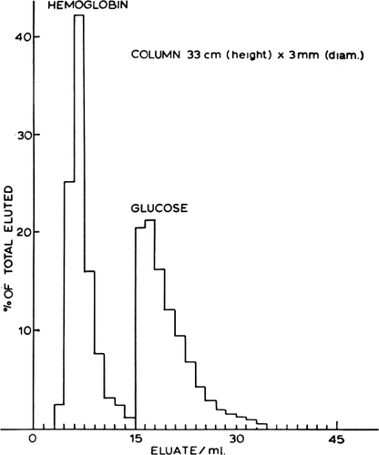
The different permeability of artificial cells for substances of different molecular size suggests their possible use in differential dialysis. Solutes of large molecular size that cannot penetrate the artificial cells are excluded and emerge from the column without retardation, while solutes capable of diffusing into the interior are retarded. shows that a column of artificial cells can separate hemoglobin from glucose almost completely in a single passage (Chang, 1965). The characteristics of the column are given in the legend. In other tests partial separation was obtained of glucose and sucrose, and of sucrose and urea; obviously, the size, permeability, and flow rate of the solute molecules are important parameters. Although this is in theory somewhat similar to those employed in chromatography using Sephadex granules, the solid polymer matrix of the Sephadex granules cannot be expected to have anything close to the high permeability characteristics of the ultrathin membrane of artificial cells. Furthermore, the artificial cell contents can modify permeant materials entering the artificial cells.
Figure 27. Column with dimensions as shown, packed with nylon membrane cells of mean diameter about 90μ, prepared by the standard method using 1% (v/v) Span 85 and jumbo magnetic stirrer speed setting of 1. Flow rate 0.09 ml/min; eluate collected in 0.2 ml fractions. (From Chang, 1965.)
Craig (1964) discussed differential dialysis using hollow tubular membranes. Here, the speed of diffusion equilibrim was secured by the use of the tubular membranes separating two aqueous phases in counter-current flow. Recent analysis (Flinn and Cherry, 1970) demonstrated the efficiency of artificial cells over a tubular system of membranes. The smallest useful hollow fibers have a diameter of 50μ with a wall thickness of 10μ. A much thinner membrane is possible with microscopic spherical membranes like artificial cells. Thus 4600 spherical membranes 3.45μ in diameter and having a wall thickness of 0.5μ would equal the core volume of the hollow fiber section. The rate of material transport across the total membrane surface of this number of spheres is nearly 400 times that for the hollow fiber. For artificial cells of 0.02μ wall thickness as prepared in this laboratory (Chang, et al., 1966), the rate would even be greater. The main advantage of artificial cells is the combination of high surface area to volume relationship and ultrathin membranes. No other membrane systems can at present have a comparable efficiency.
DISCUSSION
From the results obtained so far, artificial cells possess some of the simpler biophysical properties of biological cells. Of special importance are their permeability characteristics. The results obtained are as shown (, , and ).
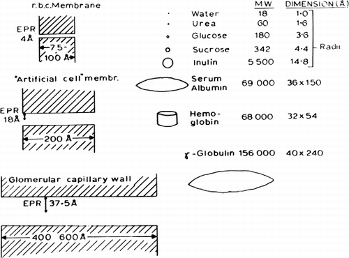
The equivalent pore radius of 18 Å for the membranes of nylon artificial cells is midway between that for human erythrocyte membranes (4.2 Å) and glomerular capillary walls (35.5 Å). Thus although molecules of small molecular dimensions can readily cross the membranes, macromolecules like ovalbumin (molecular radius of 28.5 Å), hemoglobin (molecular radius of 32.5 Å), and a number of enzymes studied, cannot leak out of the artificial cells in which they have been enclosed (). The equivalent pore radius of 18 Å is slightly smaller than that of cellulose membranes; however, the much thinner nylon membrane (200 Å) results in a permeability constant P for urea of 2×10⁻⁴ cm/sec, and the large surface area to volume relationship of the artificial cells results in an extremely rapid equilibration of solute (e.g. for urea, half-time of 4.3 seconds across artificial cells of 207μ mean diameter). Preliminary experiments indicate that, as would be expected, the half-time for equilibration is reduced even further when artificial cells of smaller diameters are tested. The permeability properties of such enclosing polymer membranes thus fulfill most of the requirements for artificial cells described in the introductory section. Thus protein, enzyme, or suspension enclosed within these artificial cells would not leak out, but small molecules like substrates or toxins can equilibrate rapidly across the artificial cell membranes. Permeability characteristics of artificial cells can be modified by lipid coating, charge, carrier molecules, and others.
