Abstract
Objective. Magnetic resonance imaging (MRI) is an established modality in clinical use but may be potentially underutilized to visualize and investigate biomaterials. As its use is totally contra-indicated only for ferromagnetic devices, it was employed to visualize deployment, biofonctionality, healing, and biodurability of a commercially available endovascular device, namely the Medtronic-AVE AneuRx. The quality of the observations coupled with the absence of ionizing radiations are likely to make this technique an attractive imaging modality in the future. Method. The potential benefits of the MRI technique were investigated in a GE Vectra-MR 0.5T MRI for the Medtronic-AVE AneuRx endovascular prosthesis, under different conditions: undeployed i.e., inserted in the delivery cartridge as received from the manufacturer (step 1), deployed in a mock glass-aneurysm tube (step 2), and as a pathological explant harvested at the autopsy of a patient (step 3). The device was submitted to X-rays for examination in addition to MRI. At step 3, the device was further investigated with light microscopy and scanning electron microscopy (SEM) together with X-ray diffraction. Results. The device which was inserted and pleated in the delivery cartridge did not demonstrate any significant observation either in MRI or in X-rays. When it was deployed in the mock aneurysmal glass tube, light artefacts were associated with the T2 weighed FSE images around the Nitinol whereas X-rays gave images of indisputable interest. Similar results were noted using the explanted device. Very high contrasts were obtained with T1 whereas T2 images were almost defect free. The X-rays allowed to accurate imaging of the Nitinol skeleton but were poor to discriminate between the different tissues. Pathology observations using light microscopy were not really challenged, as the magnetic resonance imaging was performed using a 0.5T machine. Discussion. The benefits of magnetic resonance imaging as a quality control technique to examine an endovascular device within its cartridge remains ill defined. Similarly, the role of conventional X-rays is unknown. The observation of devices fully deployed in a mock aneurysmal glass-tube under MRI are potentially useful but X-rays images allowed better definition. The MRI examination of the explanted device does permit observations related to the healing of the device that might be obtained in vivo and, thus offers new avenues for the follow-up of implanted devices. The pathological investigations brought additional informations about the tissues and the corrosion of the Nitinol. However, it is unlikely that MRI will permit detailed analysis of the biomaterials and in particular the corrosion process of the stents. Conclusion. These early observations of the follow-up of devices using MRI warrant further investigation. The absence of ionizing radiation with MRI makes this technique particularly attractive. As there is no emission of ionizing radiation associated with magnetic resonance, it is recommended that further investigation using this environment friendly technique for the follow-up of devices made of biomaterials that are MRI compatible.
Introduction
Aneurysm exclusion is recommended for the treatment of abdominal aorta aneurysms whose diameter is greater than 5.5 cm. Rupture risk is related to diameter size. About 50% of ruptured aneurysms are well above 7 cm (Conway et al., Citation[[2001]]; Johnston, Citation[[1994]]; Limet et al., Citation[[1991]]; Sperpetti et al., 1985). For many years conventional open surgery for the resection of nonruptured aneurysms was proved to be highly rewarding and durable treatment option (Riviere, Citation[[1990]]). More recently, technological advances using endovascular techniques have supported the development of several endovascular devices (Allen et al., Citation[[1997]]).
More than 10 years have elapsed since Parodi's initial paper (Parodi et al., Citation[[1991]]). The concept of minimallly invasive vascular surgery is now well accepted as it may allow the treatment of AAA in high operative risk patients. However, nephrotoxicity of the contrast agents cannot be ignored as it may result in renal failure or worsening renal function (Brismar et al., Citation[[1991]]; McClennan, Citation[[1990]]). Occlusive and aneurysmal arterial diseases can also be treated through laparoscopy, as initiated by Dion et al., Citation[[2001]]) and adapted by Juhan (Alimi et al., Citation[[2001]]) and Turnipseed et al., Citation[[2001]]). Resection of aneurysms might also be treated with the same approach but the in situ deployment of the device previously inserted in a catheter that is brought at the site of the aneurysm through the femoral artery is more attractive and is in development worldwide (Dion et al., Citation[[2000a]], Citation[[2000b]]; Stroman et al., Citation[[1996]]). Despite the high performance of equipments for digital angiography, spiral CTs, X-rays, there are still an inherent amount of ionizing radiation emission (Cordoliani et al., Citation[[1999]]; Giraud et al., Citation[[2001]]; Walter et al., Citation[[1998]]; White et al., Citation[[1995]]). It is therefore of paramount importance to investigate magnetic resonance imaging (MRI) for visualization not only at deployment but for the follow-up at regular intervals of time with or without any complication (Burl et al., Citation[[1999]]; Dumoulin et al., Citation[[1993]]; Hilfiker et al., Citation[[1999]]; Shimizu et al., Citation[[1998]]). As no suture is used to securely immobilize the endovascular device within the arterial tree, the device may slip and thus its biofunctionality can be impaired, which may potentially result in aneurysm rupture and patient mortality (Guidoin et al., Citation[[2000]]; Hölzenbein et al., Citation[[2001]]; Prinssen et al., Citation[[2001]]).
A control of the position of the device every three months sounds therefore recommendable. As X-rays, because of their ionizing properties, could raise some question marks when employed systematically, it is appropriate to investigate the capacities of MRI. It must be emphasized that deployment of medical devices at the pathological site by minimally invasive surgery is a critical operation and requires well trained operators (Beebe et al., Citation[[2001]]). Excellent visualization is a key-issue for the success of the procedure (Engellan et al., Citation[[2000]]; Liu et al., Citation[[2000]]). In addition, the follow-up of the device for its biofunctionality only, is not sufficient. It is important to be aware of the biocompatibility of the polymer and the metallic structure as well as the pathology of the aneurysmal sac. However, the MRI observations may provide a virtual biopsy and correspond to observations that can be confirmed in histology (Helft et al., Citation[[2001]]; Neschis et al., Citation[[2001]]; Worthley et al., Citation[[2000]]).
It is with this background that the authors hereby propose to assess the MRI visibility of a specific endovascular device and confirm the possibility of its deployment under MRI observation. A device harvested at the autopsy of a patient together with the aneurysmal sac is also investigated. In addition to the observations noted, the authors reflect upon the potential applications of MRI in the biomaterials field.
Material and Method
The Endovascular Device
The AneuRx endovascular device selected for this series of investigations, was manufactured by Medtronic AVE, Santa Rosa, CA, USA. It was available as a bifurcation together with a contralateral limb and extension cuffs (Mc Arthur et al., Citation[[2001]]). The tubes were made of a thin wall of a woven multifilament polyester supported by self-expanding stents sewn with a multifilament polyester suture to this tube. The stents were made of Nitinol, a shape memory alloy, with an equimolarity of titanium and nickel.
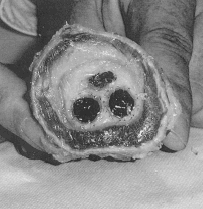
These investigations required two bifurcations and two contralateral limbs such as received from the manufacturer and still inserted in their cartridges; they were deployed in a mock aneurysmal glass-tube (). A bifurcation of the same configuration with its contralateral limbs was harvested at autopsy. The explanted device was harvested en bloc at autopsy together with the aneurysmal sac whose content was almost completely solidified ().
Figure 1. The AneuRx stent-graft as deployed in the mock aneurysmal glass tube. The bifurcation is obtained by deploying a straight contra-lateral limb inside the shorter limb of a bifurcation (A) leading to a bifurcation with an almost perfect reversed γ shape (B). The limbs separate downstream the aortic section and can be deployed in the iliac arteries (C) at an angle that can be adapted to most of the patients (D).
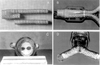
Figure 2. Cross section of the device harvested at autopsy. The distended wall of the aorta delineating the aneurysmal sac is well demonstrated. The content of the aneurysmal sac is well solidified except for a small tiny canal whereas the two limbs of the device are well encapsulated and in close contact.
X-Rays
The specimens were observed in a numerical high resolution X-ray system (Faxitron Corp., Wheeling, IL, USA) fitted with a 5.5 cm CCD camera, which provided digitized images (1024 × 1024 pixels large). Observations were carried out at a 26 kV accelerating voltage and exposure durations were limited to 10 s each. After adjustment of contrast and brightness micrographs were transfered to a Photoshop software, (Release 5-0 of Adobe System Edinburgh, Scotland) and saved under BMP format in 256 grey levels.
Magnetic Resonance Imaging
Investigations were carried out at the CIMA (Center d'Imagerie Médicale Avancée, at the Center Hospitalier of Compiegne, France), a partnership structure between the University of Technology of Compiegne and private and public institutions of the same city. The MRI machine was a GE Vectra MR 0.5T (General Electric, Buc, France).
Amongst various sequences tested 3D T1 spoiled gradient echo and T2 FSE (fast spin echo) sequences were selected as most popular routine clinical sequences, and gave the best results both in terms of resolution and contrast. The 3D T1 spoiled gradient echo sequence was preferred to standard spin-echo (SE) T1 to analyze extremely thin slices, thanks to a high signal ratio in 3D and showing higher T1 contrast. This allowed 1.0 × 0.47 × 0.47 mm voxels and so good macroscopic visualization. The T2 FSE sequence covered approximately the same volume of sample, with lightly discontinuous 2D, highly T2 weighted slices setting 4 × 0.6 × 0.6 mm voxels. To obtain images as good as possible on virgin and explanted devices, total acquisition time was not taken into account, but optimal signal to noise per unit of time was preferred.
The virgin devices either left in the cartridge or deployed in an aneurysmal shaped blown glass tube to mock the in vivo deployment and illustrate the aneurysmal sac. It was therefore possible to obtain images of the devices without tissue environment. For the investigations, the devices were placed into a water bath at 37°C. The temperature was monitored by a calibrated thermistance (NS 03K0222) during all the MR sequences and remained stable during acquisitions with less than 0.2°C variations. The acquisition parameters were chosen to improve the signal/noise ratio with sufficient T1 waiting and TE = 12 ms was the minimum full echo on this machine. Today, the gradients new technology allows minimum TE of less than l ms. In addition, sufficient T2 contrast was obtained between liquids and soft tissues at TR = 2300 ms and higher average members to reduce noise.
Therefore the following sequences were selected for the virgin devices:
3D T1 spoiled gradient echo: TR/TE = 100/12, alpha = 55°, FOV = 16 cm, matrix 256 × 256, thickness = 1 mm, Nex = 1, BW = 5 kHz, acquisition time = 21 min.
T2 FSE fast (spin echo): TR/TE = 3000/110, f = 4, FOV = 16 cm, matrix 256 × 256, thickness = 4 mm, interslice spacing = 1 mm. Nex = 2, BW = 5 kHz, 11 slices, acquisition time = 6 min.
Similar sequences for the explanted device were employed with longer acquisition times:
3D T1 spoiled gradient echo: TR/TE = 150/12, alpha = 60°, FOV = 12 cm, matrix = 256 × 256, thickness = 1 mm, Nex = 1, BW = 5 kHz, 60 slices, acquisition time: 35 min.
T2 FSE fast spin echo: TR/TE = 2300/120, FOV = 16 cm, matrix 256 × 256, thickness = 4 mm, interslice spacing = 1 mm, Nex = 10, reduction factor = 3, BW = 5 kHz, 11 slices, acquisition time = 32 min.
Histology
In order to further investigate the interface between the fibrous tissues, the polyester fabric and the Nitinol stents in the explanted device, half of the specimen was embedded in methyl methacrylate as it is the technique best adapted to any explant incorporating metallic components and/or hard and mineralized tissues.
Briefly, methylmethacrylate containing 200 ppm of hydroquinone, an inhibitor of polymerization was purified by repeated alkali washings and frozen at −20°C. Benzoyl peroxyde, a polymerization accelerator was added and dissolved until reaching a concentration of 1%. The final accelerated medium was completed by adding dibutylphthalate to a final concentration of 10%. The final solution was stored at −20°C. All reagents were of laboratory grade and purchased from Aldrich Chemical (Illkirsh, France) (Chappard et al., Citation[[1983]]; Zarins et al., Citation[[2001]]).
The pathological specimen received from the Department of Surgery, at Stanford University, Stanford, CA, USA, and previously fixed in formaldehyde was dehydrated in absolute acetone, were cleaned in xylene and infiltrated in the accelerated medium described above and freshly prepared. It was left in glass containers at –20°C for 3 days. This operation was repeated twice. The vial was then transferred in a water bath at room temperature to allow the polymerization process to continue for 3 weeks. The specimen was grossly trimmed to remove the excess of polymer. It was cut in semi-thin slices 300 µm thick on a precision banding saw under coolant (Exact, Hannover, Germany). The slices were affixed onto methacrylate slides by means of a UV adhesive. Grinding and polishing were performed in a numeric grinder system (Exact) to obtain slides 25–30 µm thick. They were ultimately stained with toluidine blue 0.5% in sodium borax. The slides were ready for observations in light microscopy.
For scanning electron microscopy (SEM) observations, the slides about 100 µm thick were trimmed and affixed on stubs. Further to carbon coating in a sputter machine, the specimens were observed on backscattered electrons using an emission field scanning electron microscope JEOL 6301 F (Jeol, Tokyo, Japan) coupled to an EDX detector Link Oxford (Oxford, UK).
Results
Devices Pleated in the Cartridge
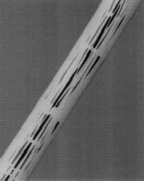
The MR images were degraded whatever condition of observation as the result of multiple artefacts caused by the Nitinol itself and the stainless steel guide, making it totally contra-indicated for observation in magnetic resonance. X-rays results were also not useful because of stent compression ().
Deployed Devices
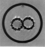
The MR images of the bifurcated device deployed together with their contralateral branch in the aneurysmal shaped glass tube immersed into water confirmed the presence of light artefact in T2 weighed FSE images around the wires of Nitinol. The exact size measured was 4 pixels in its section, i.e., 2 mm diameter ().
Figure 4. T2 weighed FSE images around the wires of Nitinol where the stents of both limbs are in close contact.
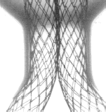
X-rays gave detailed and instructive informations about the construction of the device. The insertion of the contralateral limb was visible whereas the contraction and the compression of the stucture was clearly visible where the limbs separate ().
Explanted Device
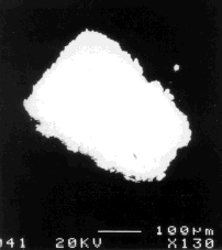
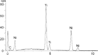
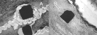
Resolution of both T1 and T2 images allowed to distinguish the clot, the endoprosthesis and the lumen. Moreover T1 images clearly showed the stretched aorta wall, distinct from the clot and regions of hyposignal between them. Image illustrated in was sagital showing long axial slice 1 × 0.46 × 0.46 mm voxels. It allows easy T1 oblique reconstruction. Very high contrasts between tissues were obtained. Contrast was especially remarkable regarding the different layers of the clot indicating the presence of an almost acellular thrombotic matrix of different ages and origins. Artefacts were relatively important in T1 images and the pixels around the prosthesis itself were distorted but did not affect the visualization of the lumen and the thrombotic matrix more or less reorganized. T2 revealed a lighter layer, indicating the presence of fluid. The images were almost artefact free (). X-rays focused on the Nitinol structure but were limited to investigate the healing as the soft tissues were not easily vizualized (). The section incorporating the two lumens of the limbs below the bifurcation and kept within the boundaries of the aneurysmal sac was observed in light microscopy (). The wall of the original aorta suffered some disruptions as only circular collagen bundles were observed in polarized light. The polymer sheath and the shape memory alloy stents (Nitinol) were easily identified. No real perforation, dismantling of the polyester woven sheath was visible. Cross-sections of the Nitinol wires demonstrated a square shape but with rounded edges. Fibrinous deposits were observed in the lumens of the blood conduits. They appeared layered and were mostly acellular either inside or outside. There was no endothelial like-cell on the flow surface. Occasionally, the internal capsule was slightly shrinked and detached from the polyester fabric as the result of the fixation. Disorganized fibrinous deposits were also observed in the external capsule of the prosthesis, in close contact with the polyester sheath and the Nitinol stents. However, the reorganization of the matrix was progressing, anticipating the formation of an external capsule. No inflammatory process was observed in contact or at distance of the foreign materials. Lymphocytes, macrophages and giant cells were rare (). Observations in SEM in the backscattered electron detection mode confirmed the square shape of the Nitinol wires; however, some minor fragmentations were beginning along the boundaries and particles escaped in the surrounding tissues ( and ).
Figure 6. Thin slice (1 mm thick) 3D T1 spoiled gradient echo. The wall of the aorta, whose continuity is disputable is well delineated and surrounds the aneurysmal sac. The content of this space presents various levels of grey: the most solidified section is almost acellular whereas the nonclotted section can be filled with various fluids. The shape memory alloy (Nitinol) of the stents causes some artefacts, within the wall of the device, delineating the boundary between the lumen of the recanalization and the aneurysm sac.
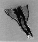
Figure 7. Thin slice (4 mm thick) T2 FSE fast spin echo. This sequence covers approximatively the same section of the specimen as illustrated in the previous figure. The contrast between the tissues is more important but the aortic wall is not as well delimited. The shape memory alloy (Nitinol) of the stent-graft causes much less artefacts compared to the previous figure.
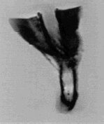
Figure 8. X-rays of the explanted device. The aneurysmal sac is delineated and this illustration confirms the presence of solidified tissues. The benefit of X-rays is mostly the visibility of the structure.
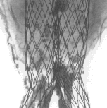
Figure 9. Light microscopy image of the section incorporating the two lumens of the limbs below bifurcation and kept within the boundaries of the aneurysmal sac. The wall of the original aorta could not be fully identified as only circular collagen bundles were observed in polarized light. The content of the aneurysmal sac was mostly solidified but remained acellular.
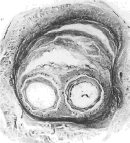
Figure 10. The polymer sheath and the shape memory alloy wires (Nitinol) were easily identified; No real perforation and nor dismantling of the polyester woven sheath was observed (A). Cross sections of the Nitinol wires demonstrated a square shape but with rounded angles in a well encapsulated structure (B).
Discussion
The recent use of medical devices involving minimally invasive surgery (Chappard et al., Citation[[1999]]; May et al., Citation[[2001]]; Parodi, Citation[[1997]]) is now a well accepted technique as well as its contribution to lowering patient morbidity. However, it is now kept under constant surveillance according to the regulations adopted by the different regulatory bureaus in most countries, and known as “materiovigilance” (Anonymous, Citation[[1999]], Citation[[2001]]; Krohg-Sorensen et al., Citation[[1999]]; Makaroun et al., Citation[[2001]]; Petrik and Moore, Citation[[2001]]; Riepe et al., Citation[[1999]]; Szilagyi, Citation[[2001]]; Wolf et al., Citation[[2000]]; Zarins et al., Citation[[2000]]). When implanted in the body any device must fulfill the requirements of the rule of the 3 Bs: biocompatibility, biofunctionality, and biodurability. The first one, biocompability means the absence of any deletorious effect for the patient. The prostheses shall not cause any exacerbated inflammatory reaction, temperature rise, carcinogenecity, immune reaction, to name just a few. The biofonctionality requirements represents the replacement of a or several functions of the ailing organ that is assisted or replaced. It generally does not replace all the functions, but is limited to those which are lethal. For example the membrane oxygenator requirements are restricted to oxygen and carbon dioxyde transfer. There is no synthesis of prostacyclin originating from the endothelial cells of the lung. The third requirement, biodurability, requires a biofunctionality to satisfy the requirements of the patient's sake. The biodurability varies depending on the type of device. A dialyzer must keep its transfer properties for a few hours only; on the opposite, a mechanical heart valve prosthesis must have a potential durability superior to the life expectancy of the patient.
The long-term success of a prosthesis, particularly an implantable device remains an outstanding challenge. Clinical observations would lead to the conclusion that the implant is initially efficient. The patient would not require reoperation for the same cause and succumb to another cause of death. Unfortunately, such an implant is not readily available. Currently a device whose characteristics have been established by destructive testing, fatigue testing, and animal experimentation is manufactured under good manufacturing practices (GMP). Quality control tests that do not impair the integrity of the device are performed mandatorily. A percentage of devices must also be tested destructively. After packaging and sterilization, the prosthesis is implanted in a sick patient by a surgeon or a radiologist performing either open surgery or minimally invasive surgery. Follow-up of the function is feasible non invasively (ultra-sounds, X-rays) or invasively using (angiography). It is not reasonable to perform biopsies to tisssues adjacents an implanted device because of potential damage and to bacteriemic contamination. Prosthetic infection is a serious permanent problem associated with biomaterials as the biofilms at the interface between the foreign surface and the living tissues are consistanly colonized by bacterias. In addition, the patient's tolerance to the device may be exacerbated and unpredictable should any degradation of the materials occur.
Therefore, several questions must be raised:
How can someone be confident that nondestructive tests to validate prostheses are sufficient?
Are the delivery and deployment of the device feasible and visible in minimally invasive surgery?
Can a follow-up technique permit to visualize the functions of the device and its characteristics?
In case of failure and prosthesis explantation, is it feasible to investigate the device nondestructively?
We consider magnetic resonance imaging to be the key technique to permanently visualize and investigate nonferromagnetic biomaterials. However, MRI may have several disadvantages or shortcomings. MRI is generally considered as a safe technique, but different factors must be born in mind:
Every machine incorporates a static magnetic field in the range of 0.5–4 T. There is no risk at such fields for short durations of examination. However should the fields be higher, i.e., 5 T or more or the durations of investigation prolonged for several hours, question marks must be raised.
Gradients of magnetic fields can generate currents likely to heat the tissues. Neuromuscular stimulations can also occur at higher intensities.
The problem of radio-frequencies in more complex. High frequencies are used in cardiology to destroy the nodes of auricular fibrillation. However in MRI, frequencies employed are in the range of 60–100 MHz. The investigations were conducted with a frequency of 21 MHz at 0.5 T. Slight increase of temperature might happen but biological damage is unlikely. However, additional caution is required taken for young children and pregnant women.
Should contrast agents be used in MRI, they are potentially less toxic than those necessary for X-ray visualization.
Finally, let us take the opportunity of investigating this model of stent-graft, i.e., the Medtronic/AneuRx, virgin and explanted, to discuss the anticipated benefits of MRI in the differents steps of the process. Let us answer the questions raised above serially:
How can someone be confident that nondestructive tests are sufficient to validate the medical devices?
It is evident that implants shall be investigated as clean and final product from the manufacturer, inserted in the cartridge, after packaging and after sterilization. This is common sense only but it is now formalized by a specific regulations.
Despite recent progress in visualization of medical devices, it sounds premature to propose MRI as a quality control tool. In ideal cases, it will be restricted to nonferromagnetic implants. The frequent association of stainless steel wires and stents or stent-grafts in commercially available devices are precluding this approach as images are highly degraded. Numerical X-rays is the undisputable tool for this kind of quality control.
Are the delivery and deployment of the device feasible and observable in MRI in real time? As X-rays cannot permit real time deployment without massive administration of specific contrast agents, variable levels of nephrotoxicity cannot be ignored. Ferro-magnetic guides would advantageously be replaced by Nitinol wire guides. Major developments in this area are mandatory.
Can a follow-up technique permit to visualize the functions of the device and its characterization? Control at 2 weeks, 1 and 3 months post-delivery and then every 3 months sounds realistic. MR imaging and ultra-sounds are totally noninvasive. CT scans and angio X require administration of a contrast agent. MR imaging can better image the pathology i.e., the graft encapsulation and the healing of the aneurysmal sac but the CT scan is still better to vizualize the metallic structure (Martin et al., Citation[[1997]]).
In case of failure and prosthesis explantation, is it feasible to investigate the device nondestructively? It is still premature to ignore conventional pathology. It is however anticipated that noninvasive techniques will dramatically improve in the forthcoming few years (Ginefri et al., Citation[[2001]]).
As the public is becoming acutely aware of the possibility of error and no longer hesitate to undertake litigations against the healthcare organizations, everyone is developing a proactive attitude more accountable to consumers. The practice of medicine requires key measures of performance and regular assessment of the outcomes. Those ideas expressed by Pyat about radiology but worth consideration everywhere result in improvement of the performance. Patient data must be collected regularly along with patient satisfaction score (Yang and Atalar, Citation[[2000]]).
As we certainly do not still have the appropriate MR machines to satisfy the needs and because of industry decisions regarding the use of stainless steel in implantology, X-rays will still be widely used in the predictable future (Cordoliani et al., Citation[[2002]]; Duchêne and Joussot-Dubien, Citation[[2001]]). However, emphasis to develop new imaging techniques MR related must be put forward. As only 10 drugs were approved in the seventies, the US Congress passed the orphan drug program to treat rare diseases in 1983. It proved to be instrumental for the development of small market drugs. Since 1983, 200 new drugs have reached the market. Nields applaudes at this decision together with the human genome sequencing and the acceleration of funding for cardiovascular disease and cancer, the top two killers of humans (Pyatt, Citation[[2001]]). Entire multipurpose whole-body imaging systems CT, MR, PET proved to be efficient and are becoming common worldwide. New developments are mandatory to make those machines organ-specific. Various types of molecular imaging systems are anticipated. Performances of commercially available equipments will be challenged by many innovators and inventors, a process dictated in part by the type of imaging probe that is found useful.
Conclusion
It is remarkable that nonferromagnetic biomaterials are not examined using MRI for the in vivo follow-up. As the healthcare organizations become more patient driven, the demands for permanent and more accurate informations will have to be fulfilled for any material (Nields, Citation[[2001]]; Stroman et al., Citation[[1999]]) but more specifically for these implanted in the cardiovascular systems (Carr et al., Citation[[2001]]; Goyen et al., Citation[[2001]]; Li and Despande, Citation[[2001]]; Pereles and Baskaran, Citation[[2001]]; Traoré et al., Citation[[2000]]).
Acknowledgments
The devices were kindly provided by Medtronic AVE. The authors are indebted to Christopher Zarins MD and Michel Letort PhD for help and guidance. One of us (Robert Guidoin) acknowledges the financial contribution of the Université de Technologie de Compiègne, the Ecole Supérieure de Physique et Chimie Industrielles de Paris (ESPCI) and the INSERM U.443 “Biomatériaux et Réparation tissulaire” for his visiting professorship. Special thanks are due to Monique Rouais and Mireille Hébert for typing the manuscript, to Florence Grizon for technical help and to Randy Guzman for revising the English.
References
- Alimi Y. S., Hartung O., Valerio N., Juhan C. Laparascopic aortoiliac surgery for aneurysm and occlusive disease: when should a minilaparotomy be performed?. J. Vasc. Surg. 2001; 33: 469–475, [PUBMED], [INFOTRIEVE], [CSA]
- Allen R. C., White R. A., Zarins C. K., Fogarty T. J. What are the characteristics of the ideal endovascular graft for abdominal aortic aneurysm exclusion?. J. Endovasc. Surg. 1997; 4: 195–202, [PUBMED], [INFOTRIEVE], [CROSSREF], [CSA]
- Anonymous. Evaluation Clinique et économique Des Prothèses Endoaortiques. ANAES, ParisFrance Juin, 1999
- Anonymous. Evaluation Des Endoprothèses Aortiques Utilisées Pour le Traitement Endovasculaire des Anévrismes de l'aorte Abdominale Sous Rénale. AFSSAPS, ParisFrance February, 2001
- Beebe H. G., Cronenwett J. L., Kutzein B. T., Brewster D. C., Green R. M. Results of an aortic endograft trial, impact of device failure beyond 12 months. J. Vasc. Surg. 2001; 33: S55–S63, [PUBMED], [INFOTRIEVE], [CROSSREF], [CSA]
- Brismar J., Jacobsson F. B. F., Jornef H. Miscellaneous adverse effects of low versus high osmolarity contrast media, a study revised. Radiology 1991; 179: 19–23, [PUBMED], [INFOTRIEVE]
- Burl M., Coutts G. A., Herlihy D. J., Hill-Cottingham R., Eastham J. F., Hajnal J. V., Young I. R. Twisted-pair RF coil suitable for locating the track of a catheter. Magn. Reson. Med. 1999; 41: 636–638, [PUBMED], [INFOTRIEVE], [CROSSREF]
- Carr J. C., Shoibani A., Russell E., Finn J. P. Contrast enhanced magnetic resonance angiography of the carotid circulation. Topics in Magn. Res. Imag. 2001; 12: 349–358, [CROSSREF], [CSA]
- Chappard D., Alexandre M., Camps M., Montheard J. P., Riffat G. Embedding iliac bone biopsies at low temperature using glycol and methylmethacrylate. Stain Techn. 1983; 58: 299–308, [PUBMED], [INFOTRIEVE], [CSA]
- Chappard D., Gaborit-Retailleau N., Montheard J. P., Baslé M. F. Photopolymerized 2-hydroxyethylmethacrylate as a mounting medium preserving immunocyto-chemical reaction and nuclear counterstain. Biotech. Histochem. 1999; 74: 135–140, [PUBMED], [INFOTRIEVE], [CSA]
- Conway K. P., Byrne J., Townsend M., Lane I. F. Prognosis of patients turned down for conventional abdominal aortic aneurysm repair in the endovascular and sonographic era: Szilagyi revisited?. J. Vasc. Surg. 2001; 33: 752–757, [PUBMED], [INFOTRIEVE], [CROSSREF], [CSA]
- Cordoliani Y. S., Grenier P., Beauvais H., Grellet J., Marshall-Depommier E., Bourguignon M. Le point sur les procédures en radiologie conventionnelle et en tomodensitométrie. Med. Nucl. Imag. Fonct. Metab. 2002; 26: 241–246, [CSA]
- Cordoliani Y. S., Hazebroucq V., Sarrazin J. L., Lévêque C., Vincent B., Jouan E. Irradiation et bonnes pratiques en tomodensitométrie hélicoïdale. J. Radiol. 1999; 80: 903–911, [PUBMED], [INFOTRIEVE]
- Dion Y. M., BenElKadi H., Boudoux C., Gourdon J., Chakfé N., Traoré A., Moisan C. Endovascular procedures under near-real-time magnetic resonance imaging guidance: an experimental feasability study. J. Vasc. Surg. 2000a; 32: 1006–1014, [PUBMED], [INFOTRIEVE], [CROSSREF], [CSA]
- Dion Y. M., Boudoux C., BenElKadi H., Moisan C. In vitro evaluation of the accuracy of open configuration MRI in endovascular techniques. Surg. Laparosc. Endosc. Percutan. Tech. 2000b; 10: 230–235, [PUBMED], [INFOTRIEVE], [CROSSREF], [CSA]
- Dion Y. M., Gracia C. R., BenElKadi H. Totally laparoscopic abdominal aortic aneurysm repair. J. Vasc. Surg. 2001; 33: 181–185, [PUBMED], [INFOTRIEVE], [CROSSREF], [CSA]
- Duchêne A., Joussot-Dubien J. Les Effets Biologiques des Rayonnements non Ionisants Medecine-Sciences. Flammarion, ParisFrance 2001; p. 85
- Dumoulin C. L., Souza S. P., Darrow R. D. Real time position monitoring of invasive devices using magnetic resonance. Magn. Reson. Med. 1993; 29: 411–415, [PUBMED], [INFOTRIEVE]
- Engellan L., Obrud J., Brockstedt S., Albrechtsson U., Norgren L., Stählberg F., Larsson E. M. MR evaluation ex vivo and in vivo of a covered stent-grafts for abdominal aortic aneurysms: ferromagnetism, heating artefacts and velocity mapping. J. Magn. Reson. Imag. 2000; 12: 112–121, [CROSSREF], [CSA]
- Ginefri J. C., Darrasse L., Crozat P. Antenne de surface supra conductrice pour la microscopie par résonance magnétique de la peau in vivo à 1.5 teslas. ITBM-RBM 2001; 22: 107–115, [CROSSREF]
- Giraud J. Y., Sage J., Taisant D., Dusserre A., Boola M., Coulomb M., Kolodié H. J., Barthelemy R., Aumont B., Ferretti G. Dose délivrée lors d'un examen scanner en acquisition hélicoïdale: influence des paramètres d'acquisition. J. Radiol. 2001; 82: 45–50, [PUBMED], [INFOTRIEVE]
- Goyen M., Debatin J. F., Ruehm S. G. Peripheral magnetic resonance angiography. Topics in Magn. Res. Imag. 2001; 12: 327–336, [CROSSREF], [CSA]
- Guidoin R., Marois Y., Douville Y., King M. W., Castonguay M., Traoré A., Formichi M., Staxrud L. E., Norgren L., Bergeron P., Becquemin J. P., Egana J. M., Harris P. L. First generation aortic endografts: analysis of explanted Stentor devices from the Eurostar registry. J. Endovasc. Ther. 2000; 7: 105–122, [PUBMED], [INFOTRIEVE], [CROSSREF], [CSA]
- Helft G., Worthley S. G., Fuster V., Zamon A. G., Schechter C., Osende J. I., Rodriguez O. J., Fayad Z. A., Fallou J. T., Bademon J. J. Atherosclerotic aortic component quantification by non invasive magnetic resonance imaging: an in vivo study in rabbits. J. Am. Coll. Cardiol. 2001; 37: 1149–1154, [PUBMED], [INFOTRIEVE], [CROSSREF], [CSA]
- Hilfiker P. R., Qinck H. M., Debatin J. F. Plain and covered stent-grafts: in vitro evaluation of characteristics at three dimensional MR angiography. Radiology 1999; 211: 693–697, [PUBMED], [INFOTRIEVE], [CSA]
- Hölzenbein T. J., Kretschmer G., Thurnker S., Schoder M., Ashin E., Lammer J., Polterauer P. Midterm durability of abdominal aortic aneuryms endograft repair: a word of caution. J. Vasc. Surg. 2001; 33: S46–S54, [CROSSREF], [CSA]
- Johnston K. W. Non ruptured abdominal aortic aneurysm: six year follow-up results from the multicenter prospective Canadian aneurysm study. The Canadian Society for Vascular Surgery Aneurysms Study Group. J. Vasc. Surg. 1994; 20: 163–170, [PUBMED], [INFOTRIEVE], [CSA]
- Krohg-Sorensen K., Brekke M., Drolsum A., Krernebo K. Periprosthetic leak and rupture after endovascular repair of abdominal aortic aneurysm: the significance of device design for long-term results. J. Vasc. Surg. 1999; 29: 1152–1158, [PUBMED], [INFOTRIEVE], [CSA]
- Li D., Despande V. Magnetic resonance imaging of coronary arteries. Topics in Magn. Res. Imag. 2001; 12: 337–348, [CROSSREF], [CSA]
- Limet R., Sakalissan N., Albert A. Determination of the expansion rate and incidence of rupture of abdominal aortic aneurysms. J. Vasc. Surg. 1991; 14: 540–548, [PUBMED], [INFOTRIEVE], [CROSSREF]
- Liu C. Y., Farahni K., Lu D. S. K., Duckwiler G., Oppelt A. Safety of MRI-guided endovascular guidewire applications. J. Magn. Reson. Imag. 2000; 12: 75–78, [CROSSREF], [CSA]
- Makaroun M. S., Deaton D. H. The Endovascular Technologies Investigators. Is proximal aortic neck dilatation after endovascular aneurysm exclusion a cause for concern?. J. Vasc. Surg. 2001; 33: S39–S45, [PUBMED], [INFOTRIEVE], [CROSSREF], [CSA]
- Martin A. J., Ryan L. C., Gotlief A. I., Henkelman R. M., Foster F. S. Arterial imaging with histologic correlation. Imag. Therap. Techn. 1997; 17: 189–202, [CSA]
- May J., White G. H., Waugh R., Ly C. N., Stephen M. S., Jones M. A., Harris J. P. Improved survival after endoluminal repair with second-generation prostheses compared with open repair in the treatment of abdominal aortic aneurysm: a 5 year concurrent comparison using life table method. J. Vasc. Surg. 2001; 33: S21–S26, [PUBMED], [INFOTRIEVE], [CROSSREF], [CSA]
- Mc Arthur C., Teodorescu V., Eisen L., Morrissey N., Faries P., Hollier L., Marin M. L. Histopathologic analysis of endovascular stent graft from patients with aortic aneurysms: does healing occur?. J. Vasc. Surg. 2001; 33: 733–738, [CROSSREF], [CSA]
- McClennan B. L. Ionic and non ionic iodinated contrast media: evolution and strategies for use. Am. J. Radiol. 1990; 155: 225–233, [CSA]
- Neschis D. G., Velasquez O. C., Baum R. A., Roberts D., Carpenter J. P., Golden M. A., Mitchell M. E., Barkr C. P., Pyeron A., Fairman R. M. The role of magnetic resonance angiography for endoprosthetic design. J. Vasc. Surg. 2001; 33: 488–494, [PUBMED], [INFOTRIEVE], [CROSSREF], [CSA]
- Nields M. W. Congress should pass an “Orphan device low” to spin development. Incertives would encourage funding for devices that face small markets despite their importance. Diagnostic Imaging Sept., 2001; 29, 31–33
- Parodi J. C. Endoluminal treatment of arterial diseases using a stent graft combination: reflections 20 years after the initial concept. J. Endovasc. Surg. 1997; 4: 3–4, [PUBMED], [INFOTRIEVE], [CROSSREF], [CSA]
- Parodi J. C., Palmaz J. C., Barone H. D. Transfemoral intraluminal graft implantation for abdominal aortic aneurysm. Ann. Vasc. Surg. 1991; 5: 491–499, [PUBMED], [INFOTRIEVE]
- Pereles F. S., Baskaran V. Abdominal magnetic resonance angiography: principles and practical appication. Topics in Magn. Res. Imag. 2001; 12: 317–326, [CROSSREF], [CSA]
- Petrik P. V., Moore W. S. Endoleaks following endovascular repair of abdominal aortic aneurysm: the predictive value of preoperative anatomic factors. A review of 100 cases. J. Vasc. Surg. 2001; 33: 739–744, [PUBMED], [INFOTRIEVE], [CROSSREF], [CSA]
- Prinssen M., Wever J. J., Mali W. P. Th. M., Eikelboom B. C., Blankensteijn J. D. Concerns for the durability of the proximal abdominal aortic aneurysm endograft fixation from a 2-year and 3-year longitudinal computed tomography angiography study. J. Vasc. Surg. 2001; 33: S64–S69, [PUBMED], [INFOTRIEVE], [CROSSREF], [CSA]
- Pyatt R. S., Jr. Let us be Accountable for Improving the Quality of Imaging. Maintening Status quo just would not do in a Service-driven World of Demanding Healthcare Consumers. Diagnostic Imaging Jan., 2001; 25, 27, and 63
- Riepe G., Heilberger P., Umscheid T., Chakfé N., Raithel D., Stelter W., Morlock M., Kretz J. G., Schnoder A., Imig H. Frame dislocation of body middle rings in endovascular stent tube grafts. Eur. Vasc. Endovasc. Surg. 1999; 17: 28–34, [CROSSREF], [CSA]
- Riviere J. Le risque opératoire actuel de la chirurgie élective des anévrismes de l'aorte abdominale sous-rénale. Le groupe ARCHIV. Les anévrismes de l'aorte abdominale sous-rénale, E. Kieffer. AERCV, Paris 1990; 227–234
- Serpetti A. V., Schultz R. D., Feldhans R. J., Peetz D. J., Fasciono A. J., McGill J. E. Abdominal aortic aneurysm in elderly patients. Selective management based on clinical status and aneurysm expansion rate. Am. J. Surg. 1985; 150: 772–776, [CROSSREF]
- Shimizu K., Mulkern R. V., Oshio K., Panysh L. P., Yoo S. S., Kikinis R., Jolesz F. A. Rapid tip tracking with MRI by a limited projection reconstruction technique. J. Magn. Reson. Imaging 1998; 8: 262–264, [PUBMED], [INFOTRIEVE], [CSA]
- Stroman P. W., Dorvil J. C., Marois Y., Poddevin N., Guidoin R. In vivo time course studies of the tissue response to resorbable polylactic acid implants by means of MRI. Magn. Reson. Med. 1999; 42: 210–214, [PUBMED], [INFOTRIEVE], [CROSSREF]
- Stroman P. W., Roby P., Alikacem N., Martin L., Mayanloo M., Formichi M., Guidoin R. G. Will it be feasible to insert endoprostheses under interventional MRI?. J. Endovasc. Surg. 1996; 3: 396–404, [PUBMED], [INFOTRIEVE], [CROSSREF], [CSA]
- Szilagyi D. E. The problem of healing of endovascular stent grafts in the repair of abdominal aortic aneurysms. J. Vasc. Surg. 2001; 33: 1283–1285, [PUBMED], [INFOTRIEVE], [CROSSREF], [CSA]
- Traoré A. S., Woerly S., Doan V. D., Marois Y., Guidoin R. In vivo magnetic resonance imaging and relaxometry study of a porous hydrogel implanted in the trapezius muscle of rabbits. Tissue Eng. 2000; 6: 265–278, [CROSSREF], [CSA]
- Turnipseed W. D., Carr S. C., Tefera G., Acher C. M., Hoch J. R. Minimal incision aortic surgery. J. Vasc. Surg. 2001; 34: 47–53, [PUBMED], [INFOTRIEVE], [CROSSREF], [CSA]
- Walter F., Hemot P., Blum A., Hirsch J. J., Béot S., Guillemin F., Boccaccini H., Regent D. Valeur comparative de l’angio-IRM, du scanner hélicoïdal et de l’angiographie numérisée dans le bilan préopératoire des anévrismes de l’aorte abdominale. J. Radiol. 1998; 79: 519–539
- White R. A., Verbin C., Kopchok G., Scoccianti M., De Virgilio C., Donayre C. The role of cinefluoroscopy and intrvascular ultrasonography in evaluating the deployment of experimental endovascular prostheses. J. Vasc. Surg. 1995; 21: 365–374, [PUBMED], [INFOTRIEVE], [CSA]
- Wolf Y. G., Fogarty T. J., Olcott C., IV, Hill B. B., Harris E. J., Mitchell R. S., Miller D. C., Dalman R. L., Zarins C. K. Endovascular repair of abdominal aortic aneurysms: eligibility rate and impact on the rate of open repair. J. Vasc. Surg. 2000; 32: 519–523, [PUBMED], [INFOTRIEVE], [CSA]
- Worthley S. G., Helft G., Fuster V., Fayad Z. A., Fallon J. T., Osende J. I., Roque M., Shinnar M., Zaman A. G., Rodriguez O. G., Verhallen P., Badimon J. J. High resolution ex vivo magnetic resonance imaging of in situ coronary and aortic atherosclerotic plaque in a porcine model. Atherosclerosis 2000; 150: 321–329, [PUBMED], [INFOTRIEVE], [CROSSREF]
- Yang X., Atalar E. Intravascular MR imaging-guided balloon angioplasty with an MR imaging guide wire: feasability study in rabbits. Radiology 2000; 217: 501–506, [PUBMED], [INFOTRIEVE], [CSA]
- Zarins C. K., White R. A., Moll F. L., Crabtree T., Bloch D., Hodgson K. J., Filliger M. F., Fogarty T. J. The AneuRx stent graft: four year results and worldwide experience 2000. J. Vasc. Surg. 2001; 33(suppl. 2)S135–S145, [PUBMED], [INFOTRIEVE], [CROSSREF], [CSA]
- Zarins C. K., Wolf Y. G., Lee W. A., Hill B. B., Olcott C., IV, Harris E. J., Dalman R. L., Fogarty T. J. Will endovascular repair replace open surgery for abdominal aortic aneurysm repair. Ann. Surg. 2000; 232: 501–507, [PUBMED], [INFOTRIEVE], [CROSSREF]
