Abstract
We report simultaneous alignment and micropatterning of carbon nanotubes (CNTs) using a high magnetic field. It is important to prepare well-dispersed CNTs for alignment and patterning because CNT aggregation obstructs alignment. In magnetic field, highly anisotropic CNTs rotate in the direction stabilized in energy. Owing to their diamagnetic nature, CNTs suspended in a liquid medium are trapped in a weak magnetic field generated by a field modulator; meanwhile, they align to the applied strong magnetic field. The alignment has been achieved not only in polymers but also in ceramic and silicone composites.
Introduction
Carbon nanotubes (CNTs) are attractive for many applications because they have high aspect ratio, excellent mechanical strength, good electrical and thermal conductivities, and high thermal stability [Citation1–3]. Because of the anisotropic structure of CNTs, their alignment and patterning in various composites is the key to the enhancement of their properties.
Many studies have been reported on the alignment of CNTs by magnetic methods [Citation4–8]. High magnetic fields made it possible to visualize magnetic effects on diamagnetic materials such as CNTs [Citation9]. Applied magnetic field induces a torque that rotates an anisotropic material to minimize the magnetic energy [Citation10, Citation11]. In many cases, a material with structural anisotropy also exhibits magnetic anisotropy. The origin of diamagnetism is the magnetization caused by the current induced by an applied magnetic field. For example, the magnitude of the magnetization induced on a benzene molecule is different when the magnetic field is applied parallel or perpendicular to the plane of benzene ring. A benzene ring has a large diamagnetic anisotropy due to the ring current of π electrons induced when a magnetic field is applied normal to the ring plane. Therefore, the normal to the benzene ring plane aligns perpendicularly to the applied magnetic field. The same phenomenon applies to the graphite sheet in which benzene rings bond in two dimensions. CNT has a structure of a rolled graphite sheet. When a graphite plane is parallel to the applied magnetic field, the CNT axis is parallel to the field, and the CNT energy is minimal. As a result, CNTs align parallel to the applied magnetic field. When a magnetic field is spatially inhomogeneous, a diamagnetic material moves to a region of smaller magnetic flux density. Therefore, CNTs become trapped in a region of weaker magnetic field. This phenomenon allows micropatterning of CNTs.
In this study, we present a facile method of the simultaneous alignment and micropatterning of CNTs using a modulated magnetic field and well-dispersed CNTs. The advantages of using magnetic fields are that it is possible to align CNTs in a thin film to any direction, both in plane and out of plane.
As-grown CNTs are usually bundled that obstructs alignment and patterning. To facilitate the alignment, in this study, CNTs were dispersed individually by a mechano chemical approach using a high-pressure emulsifier [Citation12].
Experimental details
Materials
Multiwalled CNTs (VGCF), produced by chemical vapor deposition, were provided by K K Showa Denko. Their diameters were 100–150 nm, and the lengths ∼20 μ m. The CNTs were annealed at ∼3000 °C. The annealing should have removed metal catalyst and structural defects from CNTs, as required for application in electronic devices.
As-grown CNTs are aggregated and their dispersion is the key for alignment and patterning. In this study, CNTs were dispersed by a mechanochemical approach using a high-pressure emulsifier, and the remaining clusters were removed using a centrifuge. This dispersion method is radically different from ball milling, beads milling and jet milling in that it does not use balls or beads. As a result, the contamination and damage of CNTs by collisions with balls or beads is reduced. CNTs are mixed with a solvent and pushed into a diamond nozzle by high-pressure pump. The CNT suspension passes through the nozzle at a speed of 200 m s−1 and is dispersed in a vigorous flow. The dispersion efficiency is controlled by the pressure, number of passes, size of the nozzle and temperature.
Cast films
Four kinds of CNT suspension were prepared:
Suspension 1: 0.5 g of Polystyrene (Aldrich MW23, 000) was mixed with 10 ml of tetrahydrofuran (THF) by ultrasonication. 0.01 g of dispersed CNTs was added to the polystyrene solution. Approximately 2 wt.% CNTs in polystyrene with the THF was used to prepare a sample of uniform alignment.
Suspension 2: 1.734 g of TiO2 sol-gel solution in 1-butanol (TiO2 solid ∼ 12 wt.%), 0.01 g of dispersed CNTs, and a surfactant were mixed with 1-butanol by ultrasonication for 10 min. Approximately 4.8 wt.% CNTs was dispersed in TiO2 with the 1-butanol.
Suspension 3: 0.25 g of poly(vinyl alcohol) (PVA, Nacalai tesque MW 15 000) was mixed with 5 ml of pure water by ultrasonication. 0.01 g of dispersed CNTs was mixed with 5 ml of 1% sodium dodecyl sulfate (SDS) solution in pure water. The CNT solution was added to the PVA solution and ultrasonicated for 30 min. Approximately 4 wt.% CNTs was dispersed in PVA with pure water.
Suspension 4: 0.002 g of dispersed CNTs was mixed with 0.5 g of silicone, 0.5 g of silicone oil and 0.05 g of silicone hardener by ultrasonic irradiation for 1 h. Approximately 0.4 wt.% CNTs was dispersed in silicone.
Field modulators and magnetic field
The field modulators are similar to those used in [Citation7, Citation13–15]. We made modulators with different forms and small pitches. They are composed of 200-μm-thick aluminum and iron layers, denoted by three wave lines. The other modulators were composed of aluminum and iron layers, denoted by ‘N' and ‘F'. Each modulator was placed at the center of the superconducting magnets generating horizontal or vertical magnetic fields of 5, 10 and 12 T. The sample was dropped or dip-coated on a coverglass placed on the modulators.
Results and discussion
Dispersion of CNTs
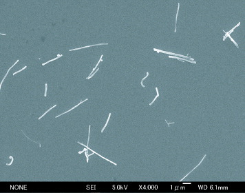
We have succeeded in dispersing CNTs with a mechanochemical approach using a high-pressure emulsifier. Figure shows a scanning electron microscopy (SEM) image of aggregated CNTs. One gram of CNTs was mixed with 200 ml of THF with a surfactant and passed 20–30 times through a high-pressure emulsifier at 100–150 MPa. After dispersion, THF was added to the CNT suspension prior to centrifugation. The top part of the centrifuged suspension was collected and dried under vacuum heating. Well-dispersed tubes 100–150 nm in diameter and 3–6 μ m in length are observed after this treatment (figure ).
Figure 1 SEM image of aggregated CNTs.
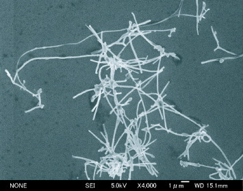
Figure 2 SEM image of dispersed individual CNTs.
Alignment of CNTs
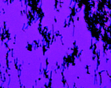
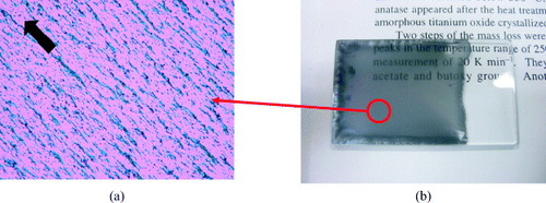
The alignment of CNTs in a polymer matrix using magnetic field was reported previously [Citation5–8]. We conducted comparative experiments using dispersed and non-dispersed CNTs. Figure shows a photograph of the CNT/polystyrene composite film prepared from suspension 1 under a uniform horizontal magnetic field. No CNT aggregates are found anywhere on the film. CNTs are aligned to the magnetic field.
Figure 3 Optical microphotograph of uniform orientation of CNTs in polystyrene composite film prepared under a 10 T horizontal magnetic field. The arrow indicates the direction of the applied magnetic field.

It was pointed out in the previous section that CNT aggregation obstructs alignment. Figure shows a photograph of the CNT/polystyrene composite film using non-dispersed CNTs under a horizontal magnetic field of 10 T. A few CNTs were aligned but large aggregates were observed throughout the film. It is clear that the dispersion of CNTs is the key for the alignment.
Figure 4 Optical microphotograph of aggregated CNTs in polystyrene composite film using nondispersed CNTs under a 10 T horizontal magnetic field.
Alignment occurs through the rotation of CNTs in suspension [Citation9]. The time required for alignment can be expressed as
1 Here μ 0 is the magnetic constant; η is the viscosity of the solvent; F(D) is a function of the aspect ratio D, F(D) ∼D2; B is the magnetic flux density; the anisotropy of the CNT magnetic susceptibility χ a = χ ∥ - χ⊥, where χ ∥ and χ⊥ are the magnetic susceptibilities parallel and perpendicular to the CNT axis. Alignment takes longer if the sample has a high aspect ratio or high viscosity. For example, we estimate an alignment time as τ ∼ 70 ms taking χ a ∼ 10−6, D= 30, CNTs diameter 100–150 nm, CNT length 3–6 μm, viscosity of ethanol at 25 ° C as 0.001084 Pa s, and B= 10 T. This agrees with experimental observation of instantaneous CNT alignment in ethanol (figure ).
Figure 5 Horizontal alignment of CNTs in ethanol.
Alignment of CNTs in a TiO2 composite is also achieved, as shown in figure (a). The ceramic composite was prepared from suspension 2 under a uniform horizontal magnetic field. After evaporating the solvent and solidifying the alignment, the TiO2 film was heated for 10 min at 150 ° C to form the ceramic. Figure (b) shows a photograph of the TiO2 film. Because CNTs are aligned without aggregates, a homogeneous film is produced.
Figure 6 (a) Horizontal alignment of CNTs in TiO2 composite and (b) photograph of the film of TiO2.
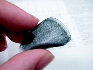
We also achieved CNT alignment in a silicone composite, as shown in figure . The composite was prepared from suspension 4 and placed for 12 h in a uniform horizontal magnetic field of 12 T until the silicone solidified. Then the sample was heated for 10 h at 50 ° C to evaporate silicone oil.
Figure 7 Horizontal alignment of CNTs in silicone composite.
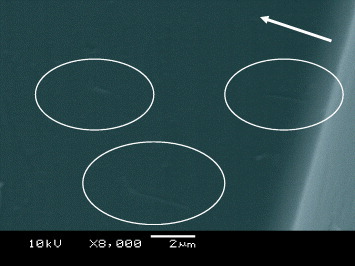
The vertical alignment of CNTs was also realized. Figure shows the cross section of the polystyrene composite film. The thickness of the film was approximately 20 μ m. A few vertically aligned CNTs are observed in the SEM image.
Figure 8 SEM graph showing vertically aligned CNTs (inside the circles) in cross section of a polystyrene composite film. The arrow indicates the direction of the applied magnetic field.
Electrical resistance of polystyrene film depended on the CNTs alignment: in-plane resistance was 0.6 MΩ for the horizontally aligned CNTs, and ∼260 MΩ for randomly oriented CNTs. The film was 20 μ m thick, contained 5 wt.% CNT and had two metal electrodes spaced by 5 mm.
Micropatterning
Field modulator
The field modulator used in this study for the patterning is shown schematically in figure . A field modulator is composed of aluminum and iron. The magnetic field is applied horizontally or vertically. CNT patterning in a polymer matrix using a field modulator has been reported in [Citation7]. We present CNT patterning using a modulator of different forms in this study.
Figure 9 (a) Schematic diagram of field modulator composed of Al and Fe.
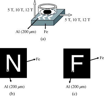
When a magnetic field is applied horizontally, the magnetic flux density is weaker over the iron layers than over the aluminum layers, as shown in figure . Owing to their diamagnetic nature, CNTs concentrate at the iron layers, where the field is weaker, and align horizontally. On the other hand, if the magnetic field is applied vertically, the intensity is weaker over the aluminum layers, as shown in figure . CNTs are concentrated at the aluminum layers where the field is weaker and align vertically. The persistence length of the field strength is 200 μ m from the modulator. In this case, it is important for suspensions to be placed less than 200 μ m from field modulator including the coverglass.
Figure 10 Diagram of movement of magnetic flux density when magnetic field is applied horizontally.

Figure 11 Diagram of movement of magnetic flux density when magnetic field is applied vertically.

Patterning with horizontal alignment
Figure shows the patterning of CNTs in the PVA composite film prepared from suspension 3 with a modulator shown in figure (b) under a horizontal magnetic field of 12 T. CNTs were concentrated on the iron surface clearly, because the suspension was placed on a coverglass (∼150 μ m), which was thinner than the persistence length.
Figure 12 CNTs were patterned and aligned horizontally, the arrow indicates the direction of applied magnetic field.

Patterning with vertical alignment
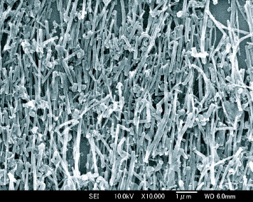
Figure shows the patterning of CNTs in the PVA composite film prepared from suspension 3 with a modulator shown in figure (c) under a vertical magnetic field of 12 T. In the case of the vertical magnetic field, the flux density is weaker on aluminum than on iron. Therefore, the CNT suspension was placed on a coverglass and then concentrated on an aluminum surface.
Figure 13 CNTs are patterned and aligned vertically.
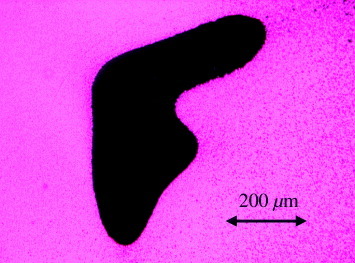
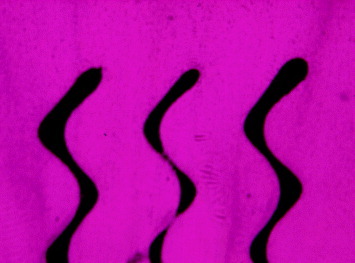
Figure also shows the patterning of CNTs in the PVA composite film prepared from suspension 3 with a modulator shown in figure (a) under a vertical magnetic field of 12 T. The CNT suspension was placed on a coverglass then concentrated on an aluminum surface. CNTs are aligned perpendicularly to the applied magnetic field. This result indicated that patterning is possible if the difference in magnetism is supplied by the modulator. Using these techniques, any type of patterning can be achieved.
Figure 14 The three wave lines indicate that CNTs are aligned perpendicular to each other.
Conclusion
The method using a field modulator placed in a magnetic field enables the simultaneous alignment and micropatterning of CNTs. Alignment in various types of suspension was achieved by solidifying the suspension liquid through polymerization and evaporating the solvent, or using ceramic or silicone composites. CNTs of various diameters can be aligned when CNTs are dispersed individually with no aggregates. A difference in electric conductivity was observed between aligned and randomly oriented CNTs in a polymer matrix. CNT patterning can be achieved everywhere when the structure of a modulator and the direction of the applied magnetic field are optimized. Therefore, this technique is useful for conducting films, semiconducting and optical devices.
Acknowledgments
We thank Professor T Kimura, Drs F Kimura and N Hirota for their valuable suggestions to this study.
References
- CalvertP 1999 Nature 399 210 http://dx.doi.org/10.1038/20326
- KashiwagiTGrulkeEHildingJHarrisRAwadWDouglasJ 2002 Macromol. Rapid Commun. 23 761 http://dx.doi.org/10.1002/1521-3927(20020901)23:13<761::AID-MARC761>3.0.CO;2-K
- MisewichJ AMartelRAvourisPTsangJ CHeinzeSTersoffJ 2003 Science 300 783 http://dx.doi.org/10.1126/science.1081294
- FujiwaraMOkiEHamadaMTanimotoYMukoudaIShimomuraY 2001 J. Phys. Chem. A 105 4383 http://dx.doi.org/10.1021/jp004620y
- KimuraTAgoHTobitaMOhshimaSKyotaniMYumuraM 2002 Adv. Mater. 14 1380 http://dx.doi.org/10.1002/1521-4095(20021002)14:19<1380::AID-ADMA1380>3.0.CO;2-V
- ChoiE SBrooksJ SEatonD LAl-HaikM SHussainiM YGarmestaniHLiDDahmenK 2003 J. Appl. Phys. 94 6034 http://dx.doi.org/10.1063/1.1616638
- PiaoGKimuraFTakahashiTMoritaniYAwanoHNimoriSTsudaKYonetakeKKimuraT 2007 Polym. J. 39 589 http://dx.doi.org/10.1295/polymj.PJ2006191
- YonemuraHYamamotoYYamadaSFujiwaraYTanimotoY 2008 Sci. Technol. Adv. Mat. 9 024213 http://dx.doi.org/10.1088/1468-6996/9/2/024213
- KimuraT 2003 Polym. J. 35 823 http://dx.doi.org/10.1295/polymj.35.823
- SakkaYSuzukiT S 2005 J. Ceram. Soc. Japan 113 26 http://dx.doi.org/10.2109/jcersj.113.26
- HirotaNHayaSSakkaY 2007 Mater. Trans. 48 2888 http://dx.doi.org/10.2320/matertrans.MI200721
- TsudaK 2008 Surface Treatment and Control of Dispersion of Nanoparticles in Electronics and Optical Material Usage Japan (Technical Information Institute Co., Ltd) p 129
- KimuraTYamatoMNaraA 2004 Langmuir 20 572 http://dx.doi.org/10.1021/la035768m
- KimuraTSatoYKimuraFIwasakaMUenoS 2005 Langmuir 21 830 http://dx.doi.org/10.1021/la047517z
- PiaoGKimuraFKimuraT 2006 Langmuir 22 4853 http://dx.doi.org/10.1021/la053505h