Abstract
Multifunctional thermoset composites were made from polyester resin, glass fiber mats and carbon nanofiber sheets (CNS). Their flaming behavior was investigated with cone calorimeter under well-controlled combustion conditions. The heat release rate was lowered by pre-planting carbon nanofiber sheets on the sample surface with the total fiber content of only 0.38 wt.%. Electron microscopy showed that carbon nanofiber sheet was partly burned and charred materials were formed on the combusting surface. Both the nanofibers and charred materials acted as an excellent insulator and/or mass transport barrier, improving the fire retardancy of the composite. This behavior agrees well with the general mechanism of fire retardancy in various nanoparticle-thermoplastic composites.
Introduction
In the recent decade, great attention has been paid to nanoparticles for making polymeric nanocomposites with exceptional properties. These nanoparticles are environmentally friendly and will not produce toxic gases. Layered silicates are widely used for an improvement in flame retardancy, but carbon nanotubes (CNTs) have been proved more efficient [Citation1–9]. It has been found [Citation1–4] that their flame retarding performance can be achieved through the formation of a relatively uniform network of carbon nanotubes, covering the entire sample surface without any cracks or gaps. The network layer re-emits much of the incident radiation back into the gas phase from its hot surface and thus reduces the transmitted flux to the underlying polymer layer, slowing down the polymer pyrolysis rate. To form efficient carbon nanotube network on the sample surface, enough carbon nanotubes should be compounded with the polymer matrix. However, addition of carbon nanotubes significantly increases the viscosity of polymer resin. In addition, it is difficult to uniformly disperse CNTs into polymer matrix due to strong van der Waals force between them. Another kind of carbon materials, carbon nanofiber, has been investigated to enhance thermal property, electrical conductivity and mechanical properties due to its highly extended structures and cost advantage [Citation10–15]. Both carbon nanotubes and carbon nanofibers have similar rope-like structures, but carbon nanofibers have much larger diameters. It has been pointed out that carbon nanofibers could enhance the fire retardancy of polymers if they are uniformly dispersed in polymer resins [Citation4]. Just like other nanoparticles, carbon nanofibers form continuous protective barrier/insulator layer through the accumulation of nanoparticles on the combusting surfaces [Citation1–4]. Only few flame resistance studies have been reported using carbon nanofibers [Citation4].
Although nanoparticles have been successfully used to enhance the fire retardancy of polymer nanocomposites, the host materials are mostly thermoplastic polymers, which have not been studied much in this regard. Thermoset composites can be made of various resins at much lower temperature. After being cured, they form cross-linked structures with high strength. Thus, these composites, especially when fiber reinforced, have become attractive engineering materials to replace conventional metals in many important sectors of industry such as aircraft, naval constructions, ships, building and offshore structures. These materials are susceptible to combustion and fire damage due to their chemical structure. This leads to concerns about their fire retardancy and structural integrity during and after the exposure to fire. In order to increase their market penetration and abide by current stringent aviation and other legislations to increase safety [Citation16–18], there is an urgent need to develop an approach to improve the fire retardancy of fiber-reinforced composites. When these nanoparticles are blended with thermoset resin prior to fiber impregnation, a few problems occur such as heavy reagglomeration, poor compatibility, poor processability, leaching, and reduced mechanical properties [Citation19, Citation20]. In the case of carbon nanofibers, relatively high loading levels will be required due to their low fire retardation efficiency that would only worsen the processing issues.
In this article, a novel method is explored to improve the fire retardancy of fiber-reinforced thermoset composites, in which a freestanding carbon nanofiber sheet is pre-planted on the sample surface. This method not only reduces aforementioned problems in processing glass fiber/polyester composites with nanoparticles but also concentrates carbon nanofiber at the combusting surface; as a result, much lower total fiber concentration is sufficient for fire protection (below 1 wt.%) [Citation21, Citation22].
Experimental details
Materials and preparation of samples
Vapor grown carbon nanofibers (Polygraf III PR19) were purchased from Applied Sciences, Inc. The fibers have diameters of 50–150 nm and lengths of 30–100 μm; they could be dispersed in aqueous solution with the aid of surfactants. Surfactants (Nano Sperse AQ) were ordered from Nanolab Company (USA). Carbon nanofiber sheet was made through filtering aqueous solution of the fibers; it had the thickness of 0.23 mm and bulk density of 0.19 g cm−3. The unsaturated polyester resin (712–6117, Eastman Chemical Company) was used as matrix material with the MEK peroxide hardener at a weight ratio of 100 : 1. Glass fiber mats had its surface density of 800 g cm−2 and average thickness of 0.85 mm.
The as-received carbon nanofiber powders were ground in a mortar with a small amount of de-ionized water. After grinding, they were transferred into a 500 ml glass beaker, and 400 ml of water was added together with four drops of surfactants. Their mixture was subsequently sonicated using a high intensity sonicator (600-watt Sonicator 3000 from Misonix Inc) for 20 min at a power of 30–50 watts. After the solution and probe were cooled down to room temperature, the solution was sonicated for 20 more min under the same condition. The as-prepared solution was allowed to settle overnight and 300 ml of the suspension was collected. The above process was repeated a few times. The final mixture was treated with the ultrasonic sonicator for 10 min before being filtered with 0.4 μm hydrophilic polycarbonate membrane with the aid of both vacuum and high-pressure air.
Resin transfer molding process had been used to manufacture three samples, in which eight plies of glass fiber mats were preformed in molds. With the aid of vacuum pump, polyester resin could flow and finally cure inside the channels of fiber mats and carbon nanofiber sheet. These samples were named of GR, GR-CNS and GR-CNF, respectively. Their composition is listed in table . Only glass fiber mats were used in sample GR. Carbon nanofiber sheet fraction was only 0.38 wt.% of thermoset resin in GR-CNS. To compare the effect of different addition methods on the fire retardancy, the same loading level of carbon nanofiber was used in GR-CNF. In GR-CNS, one ply of carbon nanofiber sheet was first sealed on the bottom of mold, which became the front surface after de-molding. Pure polyester resin was infused into GR-CNS and GR. However, to prepare GR-CNF, carbon nanofiber was first dispersed in polyester resin (treated with high speed mixer and degassed with vacuum pump) and then their mixture was fused into the mold. All samples were cured at room temperature for 24 h and post-cured in the oven for 2 h at 120 °C. Samples were cut into 100×100 mm2 squares for fire retardancy test.
Table 1 Sample composition.
Characterization
Cone calorimeter tests were performed according to the ISO5660 standard at an incident heat flux of 50 kW m2. All specimens were measured in the horizontal position and wrapped with aluminum foil except for their irradiated surface. The standard uncertainty of the measured heat release rate is ±10%. All results represent an average over three specimens. Pristine CNS and their residues collected after cone tests were subjected to thermal gravimetric analyses (TGA) using a TA Instruments TGA Q 500 at a heating rate of 10 °C min−1 from 100 to 1000 °C in N2 gas flow of 60 cm3 min−1. The standard uncertainty in sample mass measurement is ±1%. Sample morphology was characterized with scanning electron microscopy (SEM, JEOL 6300F, operated at 5 kV).
Results and discussion
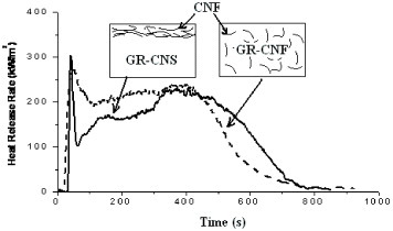
Cone calorimeter has been widely used to characterize flammability of filler/polymer nanocomposites. The most important measured parameter is the heat release rate [Citation23]. Figure shows the heat release rate curves of GR-CNS, GR-CNF and GR. Compared to GR, GR-CNS has its time to ignition shortened from 56 to 41 sec and its heat release rate lowered significantly except for the initial peak. However, the heat release rate of GR-CNF is rather similar to that of GR except for even shorter time to ignition (26 s) and slight increase of the initial peak.
Figure 1 Heat release rate curves of GR-CNS, GR-CNF and GR.
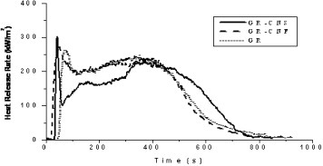
Obviously, the addition of carbon nanofibers greatly shortens time to ignition of GR-CNF, which agrees well with reported data [Citation1–9]. Among different explanations, Kashiwagi et al believed that carbon nanotubes and polymer resin have different absorption characteristics of the external emission [Citation1]. All incident heat flux of cone calorimeter cannot be rapidly transmitted into underlying materials but can be quickly absorbed by the front layer of carbon nanotubes in the case of carbon nanotube/polypropylene nanocomposites, so that a narrow layer near the front surface of a nanocomposite is rapidly heated and ignited. In this study, although GR-CNS has shorter time to ignition than GR, its time to ignition has been obviously prolonged compared with GR-CNF. In fact, GR-CNS has the same load of carbon nanofibers as GR-CNF. However, they are all concentrated at the front surface of specimen in GR-CNS, and the thickness of carbon nanofiber sheet is larger (0.23 mm) than the reported transmitted thickness of carbon nanotube networks (200 μm) [Citation1]. The front surface of GR-CNS should be heated even quicker. However, there is less polymer resin inside the front layer of GR-CNS, which might delay the ignition.
For GR-CNF and GR, the heat release rate curves nearly overlap except for their ignition stage. Therefore, there is no obvious improvement of fire retardancy through dispersing carbon nanofibers in the composites. On the contrary, GR-CNS has its heat release rate curve sharply increased at the early ignition stage and then quickly decreased to the lowest level. GR-CNS has a carbon nanofiber sheet and thus less polymer resin at the front surface. The incident heat flux can be quickly absorbed by the front carbon nanofiber sheet, which can rapidly heat and pyrolyze the surrounding materials. As a result, GR-CNS quickly reaches its heat release rate peak. After the front layer of GR-CNS has burned, the heat release rate drops down quickly. Compared with GR-CNF and GR, GR-CNS has good fire retardant performance due to its lower heat release rate before 400 s. After 400 s, GR-CNS still has much polymer left unburned, which leads to higher heat release rate as compared to GR-CNF and GR.
Sample residues were collected at the end of the cone calorimeter tests (figure ). GR-CNF and GR have less residue left at the front surface, and most glass fiber mats are exposed without being destroyed or contaminated. But GR-CNS has a unique residue, consisting of two layers. The upper one is black and has no crack or gaps. It is a soft material with a thickness of 0.64 mm, much larger than pristine carbon nanofiber sheet thickness (0.23 mm). The underlayer residue is much thinner (<0.1 mm), but it is brittle.
Figure 2 Photos of (a) GR-CNS residue, (b) GR-CNF-residue and (c) GR.

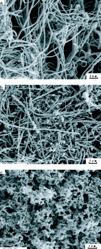
The residual materials of GR-CNS and pristine carbon nanofiber sheet were characterized with SEM (figure ). The pristine carbon nanofiber sheet mainly consists of well-dispersed long individual carbon nanofibers forming a network (figure (a)). In addition, there are some elliptical particles originating from the metal catalysts used in the nanofiber synthesis. The underlying residue is a partially burned carbon nanofiber sheet with rough surfaces. Compared to pristine carbon nanofiber, the thinner carbon nanofibers are burned out and thicker ones have survived the combustion (figure (b)); those thicker nanofibers have shortened. Clearly, the pristine carbon nanofiber sheet was partially damaged during the fire test. The upper residue consists of a uniform network of floccules with much smaller pore size than pristine and underlayer residues (figure (c)). Although it is unclear how the upper residue is formed, the existence of carbon nanofiber sheet should play an important role in their formation during combustion.
Figure 3 SEM images of (a) pristine carbon nanofiber sheet, (b) underlayer residue and (c) upper residue of the burned GR-CNS sample.
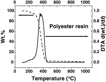
The residues of GR-CNS and pristine carbon nanofiber sheet were characterized by TGA (figure ). Their thermal stability and weight loss should give important information to their flame retardant behavior. The weight loss of pristine carbon nanofiber sheet gradually decreases with the temperature and there is only ∼3% of weight loss at 500 °C—a characteristic combustion temperature. However, the underlayer residue shows much higher weight loss ∼8% at 500 °C. Therefore, the thermal stability of the carbon nanofiber sheet is reduced by combustion. Upper residue shows medium thermal stability with ∼6% of weight loss at 500 °C. In the temperature range 100–800 °C, pristine carbon nanofiber sheet has two weak DTA peaks. Underlayer residue shows similar DTA curves except for the much stronger DTA peaks at temperatures 120–350 °C and 400–800 °C. Similarly, upper residues exhibit similar two DTA peaks different from those of pristine and underlayer residues. These peaks shift to the higher temperatures of 150–400 °C and 500–800 °C, respectively. This observation can be interpreted as the upper residue has components of carbon nanofiber and something else. As mentioned above, the composites consist of glass fiber, carbon nanofiber and polyester. Glass fiber has good thermal stability at the temperature of the cone tests. Therefore, the formation of upper residues should have relationship with carbon nanofiber and polyester. However, polyester resin completely decomposes at ∼450 °C with a broad DTA peak at 280–450 °C (figure ) and cannot be the uncertain component of the upper residue. We suggest that the upper residues consist of heavily burned carbon nanofiber and some charred materials from polyester resin. The burned carbon nanofiber is covered with those charred materials. They could survive the temperature of combusting surface (∼400–500 °C) [Citation2] and protect the underlying polymer resin.
Figure 4 (a) TGA and (b) DTA curves of pristine CNS, underlayer residues and upper residues (pristine CNS: pristine carbon nanofiber sheet).
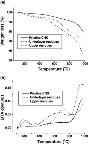
Figure 5 TGA and DTA analyses of polyester resin.
Based on the above results, the fire retardance mechanism is proposed in figure . Thermoset composites have cross-linking structures, in which nanoparticles cannot move until the cross-linking structures are destroyed. Therefore, fire retardancy of thermoset composites cannot be achieved through the accumulation of nanoparticles on the combusting surfaces. The formation of carbon nanofiber networks inside the cross-linking structures plays a crucial role in enhancing the fire retardancy of thermoset composites. When carbon nanofibers are uniformly dispersed in thermoset resin, the nanofiber concentration should be high enough so that the carbon nanofiber network is formed. GR-CNF in figure has no network of carbon nanofibers due to their low concentration (0.38 wt.%). Consequently, GR-CNF has no fire retardancy relative to pure thermoset composites. If the same loading level is used through pre-planting carbon nanofiber sheet on the surfaces of thermoset composites, such as GR-CNS, the network structures of carbon nanofiber sheet could work as an insulator/barrier on the combusting surfaces of thermoset composites. Furthermore, the carbon nanofiber sheet promotes the formation of charred materials, which works together with carbon nanofiber sheet on the combusting surfaces to enhance the fire retardancy of thermoset composites.
Figure 6 Proposed mechanism of fire retardance of GR-CNS (CNF: carbon nanofiber).
Conclusions
Fire retardancy of thermoset composites was improved through pre-planting carbon nanofiber sheet on their surfaces. This result agrees well with the main mechanism of fire retardancy in nanoparticle-filled thermoplastic nanocomposites. Carbon nanofiber sheet promotes the formation of charred materials. Carbon nanofiber sheet and charred materials can work together to re-emit the incident radiation back into the gas phase or/and to slow down the escape of the volatile products generated during combustion. This method enhanced the fire retardation efficiency of the composite containing only 0.38 wt.% of carbon nanofibers, which is far lower than 4 wt% threshold reported previously [Citation4].
References
- KashiwagiTGrulkeEHildingJHarrisR H JrAwadWDouglasJ F 2002 Macromol. Rapid Commun. 23 761 http://dx.doi.org/10.1002/1521-3927(20020901)23:13<761::AID-MARC761>3.0.CO;2-K
- KashiwagiTGrulkeEHildingJGrothKHarrisR H JrButlerK 2004 Polymer 45 4227 http://dx.doi.org/10.1016/j.polymer.2004.03.088
- KashiwagiTDuF MWineyK IHarrisR H JrShieldsJ RDouglasJ F 2005 Polymer 46 471 http://dx.doi.org/10.1016/j.polymer.2004.10.087
- KashiwagiTDuF MDouglasJ FWineyK IHarrisR H JrShieldsJ R 2005 Nature Mater. 4 928 http://dx.doi.org/10.1038/nmat1502
- GilmanJ W 1999 Appl. Clay Sci. 15 31 http://dx.doi.org/10.1016/S0169-1317(99)00019-8
- ZanettiMCaminoG 2001 Polym. Degrad. Stab. 74 413 http://dx.doi.org/10.1016/S0141-3910(01)00178-1
- TangTChenXChenHMengMJiangZBiW 2005 Chem. Mater. 17 2799 http://dx.doi.org/10.1021/cm047771c
- KashiwagiTHarrisR H JrZhangXBriberR MCiprianoB HRaghavanS R 2004 Polymer 45 881 http://dx.doi.org/10.1016/j.polymer.2003.11.036
- RibeiroS P SEstevaoL R MNascimentoR S V 2008 Sci. Technol. Adv. Mater. 9 024408 http://dx.doi.org/10.1088/1468-6996/9/2/024408
- XuY JHigginsBBrittainW J 2005 Polymer 46 799 http://dx.doi.org/10.1016/j.polymer.2004.11.091
- XieHGuHFuMZhangX 2006 Int. J. Thermophys. 27 244 http://dx.doi.org/10.1007/s10765-006-0024-7
- KumarSRathTMahalingR NReddyC SDasC KPandeyK NSrivastavaR BYadawS B 2007 Mater. Sci. Eng. B 141 61 http://dx.doi.org/10.1016/j.mseb.2007.06.002
- JimenezG AJanaS C 2007 Carbon 45 2079 http://dx.doi.org/10.1016/j.carbon.2007.05.015
- KlostermanDWilliamsMHeitkampC 2007 SAMPE J. 43 7
- KumarSRathTMahalingR NDasC K 2007 Composites: Part A 38 1304 http://dx.doi.org/10.1016/j.compositesa.2006.11.006
- KandolaB KAkondaM HHorrocksA R 2005 Polym. Degrad. Stab. 88 123 http://dx.doi.org/10.1016/j.polymdegradstab.2004.01.030
- MortaigneBBourbigotSLe BrasMCordellierGBaudryADufayJ 1999 Polym. Degrad. Stab. 64 443 http://dx.doi.org/10.1016/S0141-3910(98)00149-9
- Le LayFGutierrezJ 1999 Polym. Degrad. Stab. 64 397 http://dx.doi.org/10.1016/S0141-3910(98)00140-2
- MalteH GSumflethJGojnyF HQuaresiminMFiedlerBSchulteK 2006 Eng. Fract. Mech. 73 2346 http://dx.doi.org/10.1016/j.engfracmech.2006.05.015
- GojnyF HWichmannM H GFiedlerBBauhoferWSchulteK 2005 Composites A 36 1525 http://dx.doi.org/10.1016/j.compositesa.2005.02.007
- GouJ HLiangYWangB 2004 Int. J. Nanosci. 3 293 http://dx.doi.org/10.1142/S0219581X04002085
- GouJO'BraintSGuHSongG 2006 J. Nanomater. 32803 1 http://dx.doi.org/10.1155/JNM/2006/32803
- BabrauskasVPeacockR D 1992 Fire Saf. J. 18 255 http://dx.doi.org/10.1016/0379-7112(92)90019-9