Abstract
Ferroelectric random access memory (FeRAM) has been in mass production for over 15 years. Higher polarization ferroelectric materials are needed for future devices which can operate above about 100 °C. With this goal in mind, co-doping of thin Pb(Zr40,Ti60)O3 (PZT) films with 1 at.% Bi and 1 at.% Fe was examined in order to enhance the ferroelectric properties as well as characterize the doped material. The XRD patterns of PZT-5% BiFeO3 (BF) and PZT 140-nm thick films showed (111) orientation on (111) platinized Si wafers and a 30 °C increase in the tetragonal to cubic phase transition temperature, often called the Curie temperature, from 350 to 380 °C with co-doping, indicating that Bi and Fe are substituting into the PZT lattice. Raman spectra revealed decreased band intensity with Bi and Fe co-doping of PZT compared to PZT. Polarization hysteresis loops show similar values of remanent polarization, but square-shaped voltage pulse-measured net polarization values of PZT-BF were higher and showed higher endurance to repeated cycling up to 1010 cycles. It is proposed that Bi and Fe are both in the +3 oxidation state and substituting into the perovskite A and B sites, respectively. Substitution of Bi and Fe into the PZT lattice likely creates defect dipoles, which increase the net polarization when measured by the short voltage pulse positive-up-negative-down (PUND) method.
Introduction
Ferroelectric thin films such as Pb(Zr,Ti)O3 (PZT) have a wide variety of growing applications such as in piezoelectric devices, micro-machines, sensors and ferroelectric random access memory (abbreviated FeRAM, FRAM or F-RAM). Mass production of FeRAM has been on-going for over 15 years by Fujitsu, Panasonic, TI, and Ramtron International Corp. as noted on their internet homepagesFootnote5. Present device challenges for FeRAM are summarized in the International Technology Roadmap for Semiconductor (ITRS) FeRAM roadmap [Citation1] and in the literature [Citation2, Citation3]. Challenges for FeRAM are primarily focused on device integration [Citation4] while maintaining 10 year reliability with unlimited usage for data reading/writing, similar to volatile memories such as DRAM or SRAM.
Future generations of FeRAM will require lower operating voltage with higher net polarization values per memory cell owing to scaling issues. In addition, applications for FeRAM in the automobile market require data retention at 125 °C for >10 years. Therefore, it is essential that next-generation ferroelectric capacitors have higher polarization values with high reliability at elevated operating temperatures. In addition, material compositions are a concern for FeRAM customers because of various government regulations. Although ferroelectric memories are exempt from Reduction of Hazardous Substances (ROHS) regulations in the EU, if Pb-free devices were available, which can match the characteristics of PZT based devices, customer acceptance would likely be greater.
Extensive research and development of ferroelectric BiFeO3 (BF) thin films by the academic community has demonstrated that BF film based capacitors have a high polarization because of the high Curie temperature of BF, but they also suffer from uncontrollable high leakage conduction [Citation5]. Thus, the potential use of BF films in FeRAM will depend on whether or not these reliability issues can be resolved through materials or process innovation.
An alternative approach to BiFeO3 based films in FeRAM applications is to use the matrix of PZT and co-dope it with Bi and Fe to increase the capacitor polarization [Citation6], as has been reported with sol-gel spin coated films. Previous research on this topic has focused on adding high concentrations of BF to PbTiO3 [Citation7, Citation8], typically focusing on determining the morphotropic phase boundary in ceramics. Our previous publication [Citation9] summarizes initial results on co-doping of PZT in thin films with 5% BF, where co-doping shows potential for enhancing the ferroelectric properties. However, further research and characterization is needed to understand where low concentrations of Bi and Fe are located in the film, because sol-gel based PZT films often exhibit out-of-plane Ti/Zr profiles [Citation10], as well as to evaluate the reliability of the capacitor to repeated switching of the domains by applying a bi-polar voltages, known as fatigue testing. As a result, this study was undertaken to characterize film capacitors based on co-doped PZT with Bi and Fe and compare it to PZT capacitors.
Experimental and theoretical methods
Experimental processing and characterization
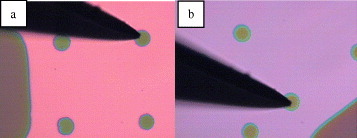
PZT(110/40/60) and PZT(110/40/60)-5%BF thin films were produced from a sol-gel solution prepared at Inostek Inc. (Korea) on Pt(111)/IrOx coated SiO2/Si wafers (see [Citation6] for processing details). Pyrolysis of the films was performed at 300 °C followed by rapid thermal annealing for crystallization at 650 °C. Powder samples were also prepared by pyrolysis at 300 °C and crystallization at 650 °C in an annealing furnace. Excess Pb (10%) was added to compensate for Pb vaporization during crystallization. Capacitor top electrodes were prepared by sputtering a 10 nm film of SrRuO3 (SRO) and then 75 nm of IrO2 through either a shadow mask (see figure ) or lift-off processed resist on PZT(-BF) films to form the top electrode. The resist and/or shadow mask were removed, and the capacitor was annealed at a temperature in the range 550–650 °C for 1 h in air to recover the sputter damage to the ferroelectric film interface.
Figure 1 Shadow mask patterned IrO2/SrRuO3 top electrodes on (a) BF-doped PZT and (b) on PZT with an average top electrode diameter of 60 μm.
X-ray diffraction (XRD) patterns of PZT-BF and PZT films were taken with a Bruker D8 μ-HR XRD2 system at Bruker AXS K.K. in Yokohama, Japan. They were recorded using 2θ values from 18 to 51° with the sample stage inclined at 50°, owing to the PZT films (111) orientation, from room temperature to 600 °C in air. Ferroelectric measurements were undertaken using Radiant RT6000HVS and FH ferroelectric testers at room temperature, where the drive voltage was applied to the bottom electrode. Fatigue testing was performed by applying ±3 V pulses from an Agilent 33250A pulse generator at 10 MHz to 15×15 μm2 capacitors that were patterned by lift-off. Raman measurements of PZT and PZT-BF powder were carried out using a Jasco NRS-2100 triple-monochromator micro-probe with a 514.5 nm laser and the spot size of 8 μm. XRD measurements of the powders were also made at SPring-8 Synchrotron in Japan. Secondary ion mass spectroscopy (SIMS) analysis of the capacitor was performed at MST (Tokyo, Japan). The capacitor net polarization was calculated using a LeCroy LT584L 1GHz digital oscillator scope with an active probe employing a 300 Ω shunt resistor and integrating the voltage drop across the resistor vs. time with four ±3 V voltage pulses, such as positive-up-negative-down (PUND) [Citation11, Citation12].
A Hitachi S4700 field-emission scanning electron microscope (FE-SEM) was used to observe the film cross-sections. Prior to observation, the samples were cleaved and lightly sputtered with Au to reduce electron charge-up. The accelerating voltage was 8 keV. The FE-SEM observations were undertaken at Tokyo Tech's Center for Advanced Materials Analysis (CAMA) on the Ookayama campus, Tokyo.
Results and discussion
As shown in figure , the PZT and PZT-BF films had a column structure as revealed by cross-sectional FE-SEM images. The PZT-(BF) film thicknesses were approximately 140 nm with a PZT-(BF) grain size on the order of 100 nm. As revealed by XRD, the PZT-BF and PZT films were strongly (111) oriented, which is the same orientation as the Pt film [Citation8]. The sample stage was tilted at an angle of 50° from the normal, also known as Psi or Chi, and the XRD patterns were peak-fitted to determine the PZT(-BF) film tetragonal lattice dimensions (figure ) using Topas software. As noted by the figure Y-axis, the PZT film exhibited lattice parameters of 4.02 Å (a-axis) and 4.12 Å (c-axis), whereas the corresponding values for PZT-BF film were 4.01 and 4.11 Å. The lattice parameter for the a-axis is slightly larger than 3.98 Å reported for PZT powders [Citation13] because of clamping by the substrate and differences in thermal expansion coefficients between PZT and Si. With Bi and Fe co-doping, the a value decreased by 0.01 Å compared to PZT with an experimental error of ±0.005 Å. The decrease in lattice dimensions has been observed previously with PZT ceramics and indicates that Bi and Fe are substituting into the PZT lattice [Citation14]. The phase transition temperature from tetragonal to cubic was observed at 350 and 380 °C for PZT and PZT-BF, respectively, as indicated by the c/a ratio approaching 1.0 (figure (c)). Because the PZT-BF had a smaller a-axis dimension, the c/a ratio for PZT-BF is slightly larger than that for PZT.
Figure 2 (a) FE-SEM images of cross-sections of PZT-BF film and (b) PZT film on Pt/IrOx coated SiO2/Si substrate.
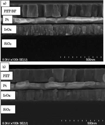
Figure 3 Temperature dependence of tetragonal c and a lattice parameters toward cubic phase transition, (a) PZT film, (b) PZT-BF film and (c) c/a ratio for the PZT and PZT-BF films.

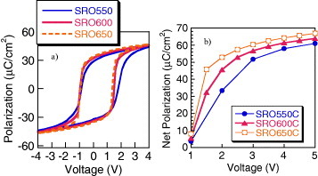
The annealing temperature after sputtering the top electrode was varied from 550 to 650 °C for the PZT-BF capacitor (figure (a)). The results indicate that the polarization values increased at higher temperature indicating that the 650 °C annealing maximized the polarization. The interface crystallinity has a strong impact on the polarization values, particularly at low voltages (figure (b)). This annealing repairs the PZT-BF/top electrode interface crystallinity that was damaged during sputtering of the top electrode [Citation15]. It is shown that higher polarization values can be obtained at lower voltage with the higher annealing temperature. Similar results were also observed with PZT capacitors.
Figure 4 (a) Hysteresis loops of PZT-BF capacitor as a function of annealing temperature measured using 4 V triangular voltage profiles at 1 kHz, and (b) net polarization measured using the PUND method and square 50 μs voltage pulses as a function of voltage and annealing temperature.
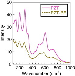
In order to understand where the Bi and Fe may be substituting into the PZT perovskite lattice, Raman spectra of PZT and PZT-BF powders were analyzed (figure ). The spectra of the PZT showed strong bands at 132, 202, 276 and 600 cm−1 with minor peaks or shoulders at 332, 441 and 720 cm−1, which are typical bands for PZT films [Citation16, Citation19]. In contrast, Bi and Fe doped PZT shows similar Raman peak wavenumbers but with much less intensity. These same powder samples were analyzed by XRD at SPring-8. Both samples showed similar overall XRD patterns but their peaks were relatively weak and broad making Rietveld analysis inconclusive of the Bi and Fe location in the PZT lattice. From these results, it appears that Bi and Fe are substituting into the PZT lattice based upon the XRD-measured increase in the tetragonal-cubic phase transition temperature (figure ). In addition, Bi and Fe substitution creates greater localized disorder in the PZT lattice as noted by the diminished Raman spectrum intensity (figure ). In a separate study, a similar decrease in Raman intensity has been observed in PbTiO3 by co-doping with Bi and Zn [Citation18].
Figure 5 Raman spectra of the PZT and PZT-BF powders measured at room temperature.
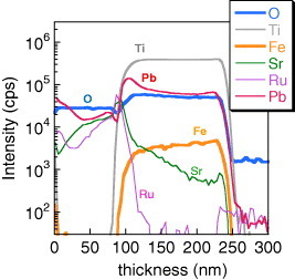
SIMS depth analysis of selected elements (excluding Bi) in the IrOx/SrRuO3/PZT-BF/Pt capacitor after annealing at 650 °C shows excess Pb at the top electrode interface (figure )Footnote6. Based upon these results, there does appear to be excess PbOx at the top interface, which was confirmed by previous x-ray photoelectron spectroscopy analysis [Citation10]. Sr diffusion from a SrRuO3 top electrode has been shown previously to be enhanced in the presence of excess Pb in the PZT film [Citation19], and capacitors which show this type of Sr interdiffusion also exhibit fatigue-free response or pronounced endurance to repeated bipolar switching.
Figure 6 SIMS elemental depth profiles of Pb, Ti, Fe, O, Sr and Ru in the IrOx/SRO/PZT-BF/Pt capacitor.
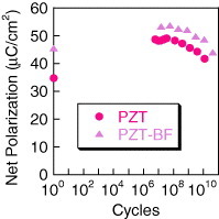
Endurance of this type of BF co-doping of PZT has not been adequately investigated. Therefore, fatigue with bipolar ±3 V voltage pulse cycling of the capacitor was carried out at 10 MHz. As noted in figure , the initial polarization of the PZT-BF is higher than that of PZT and remains higher up to 1010 cycles. Assuming that fatigue is due to charge injection and accumulation in the non-ferroelectric interface layer between the ferroelectric film and electrode [Citation20], a higher net polarization should lead to a greater loss of polarization due to higher charge injection and screening resulting in a faster fatigue onset [Citation21], if the ferroelectric interfaces are equal. However, this particular phenomenon was not observed indicating that either there are differences in the electrode interfacial layers between PZT and PZT-BF, or this particular model is not applicable to this material. A previous study on co-doping of PZT with Bi and Zn showed higher polarization compared to undoped PZT and improved fatigue endurance even with Pt electrodes [Citation22]. Therefore, it appears that limited co-doping of PZT may, with process optimization, increase the net ferroelectric polarization while improving the capacitor endurance to bipolar switching.
Figure 7 Net polarization of the PZT and PZT-BF as a function of the number of switching cycles at ±3 V and 10 MHz, where the net polarization (or sometimes called Qsw) was measured at 3 V using 100 ns pulses and the PUND method.
Previous studies have examined the impact of either Bi or Fe doping in PZT films and ceramics. In the case of Fe doping, its ionic radius favors the B site with a 3+ oxidation state in the ABO3 perovskite structure, which forms an oxygen vacancy to maintain charge neutrality when substituting for Zr4+ and Ti4+. Typically, this results in lower polarization in PZT and higher coercive voltage [Citation23]. Bi, on the other hand, when doped up to 5%, does not change the ferroelectric properties [Citation24]. Bi also typically has a 3+ oxidation state such as in BiFeO3, but because of its larger ionic radius, it is likely to substitute for the Pb2+ in the perovskite A-site. At the same time, Bi3+ also creates an A-site vacancy in PZT lattice when replacing Pb2+ resulting from charge neutrality. So the chemical formula for PZT with 1 at.% Bi and Fe substitution on the A and B site, respectively, is expressed below in equation (Equation11 ):
1
Similar research has been undertaken on 1 at.% La and 0.5 at.% Fe co-doping of PZT, and an (FeZr,Ti–Vo) defect dipole was identified using multi-frequency paramagnetic resonance spectroscopy [Citation25]. This same type of defect dipole present with (La3+, Fe3+) donor-acceptor pairs is also expected with co-doping Bi and Fe in the PZT film. Research on defect dipoles in perovskite ferroelectrics, such as PbTiO3, has shown that the defect dipole can contribute to polarization values [Citation26] and likely switch orientation in an applied electric field. The impact of acceptor dopants in the B-site in BaTiO3 indicates reorientation of the domains, when aged, because of the presence of oxygen vacancies [Citation27]. Therefore, the interaction between defect dipoles with an A-site vacancy in the perovskite structure and oxygen vacancy on the polarization vector will depend upon the applied electric field and the free energy [Citation28]. Previous research on Bi and Zn doping of PbTiO3 predicts higher polarization values with co-dopants concentrations greater than 10% [Citation29]. Considering that the Bi and Fe concentrations are basically on the order of one atomic per cent in PZT, these dopants are likely to substitute independently or randomly, based upon probability and free energy. In order to clarify the impact of low concentrations of Bi and Fe co-doping on PZT ferroelectric properties, first principle calculations of PZT-BF are needed similar to what has already been done with Bi(Zn,Ti)O3 [Citation30] in order to determine which sites in the co-doped PZT lattice would give the lowest free-energy. Secondly, further process optimization by annealing at higher temperatures (>650 °C) is needed to prepare powders with better crystallinity for more detailed XRD and Rietveld analysis.
Conclusions
XRD measurements of PZT-5% BiFeO3 (BF) and PZT films showed an increase in the tetragonal to cubic phase transition temperature from 350 to 380 °C with Bi and Fe co-doping, indicating that Bi and Fe are substituting into the PZT lattice. Raman spectra revealed decreased band intensity with Bi and Fe co-doping of PZT compared to PZT, which is attributed to localized disorder. Polarization hysteresis loops show similar values of remanent polarization, but the pulse-measured polarization values with PZT-BF were higher and showed higher endurance to repeated cycling up to 1010 cycles. It is proposed that Bi and Fe are both in the +3 oxidation state in PZT and substituting into the perovskite A and B sites, respectively. Substitution of Bi and Fe into the PZT lattice likely creates defect dipoles that increase the net polarization when measured by the PUND method.
Acknowledgments
The authors wish to acknowledge that the XRD measurements of the films over a range of temperatures and lattice parameter fitting were performed at Bruker AXS, KK by Dr H Morioka and Dr K Saito.
Notes
5 Toshiba has developed advanced FeRAM technology but has yet to announce plans for mass-production.
6 Bi and Fe were not measured by SIMS analysis in figure for the PZT-BF film. Bi, Fe, O and Pb were measured for PZT-BF film and published previously in [Citation8]. However, in [Citation8], figure , the SIMS depth profiles are not identified. The elements are oxygen (blue), Pb (red), Fe (orange) and Bi (purple) in decreasing order of concentration in [Citation8] figure .
References
- International Technology Road Map for Semiconductors 2009 Edition, available on-line from ITRS web site or from International Sematech Inc., ITRS Department Austin, Texas, USA
- KawashimaSCrossJ S 2009 Embedded Memories for Nano-Scale VLSIs KZhang New York Springer Science + Business Media p 279
- IshiwaraHOkuyamaMArimotoY 2003 Ferroelectric Random Access Memories: Fundamentals and Applications Berlin Springer
- CrossJ SKoutsaroffI P 2010 Taikabutsu 62 162
- SeidelJ et al 2009 Nat. Mater. 8 229 http://dx.doi.org/10.1038/nmat2373
- KooYCheonJ-HYeomJ-HHaJKimS-HHongS K 2006 J. Korean Phys. Soc. 49 S514
- ZhuW-MGuoH-YYeZ-G 2008 Phys. Rev. B 78 014401 http://dx.doi.org/10.1103/PhysRevB.78.014401
- WoodwardD IReaneyI MEitelR ERandallC A 2003 J. Appl. Phys. 94 3313 http://dx.doi.org/10.1063/1.1595726
- CrossJ SShinozakiKYoshiokaTTanakaJKimS HMoriokaHSaitoK 2010 Mater. Sci. Eng. B 173 18 http://dx.doi.org/10.1016/j.mseb.2010.02.005
- AmanumaKHaseTMiyasakaY 1994 Appl. Phys. Lett. 65 3140 http://dx.doi.org/10.1063/1.112461
- BrazierMMansourSPatonEMcelfreshE 1997 Integr. Ferroelectr. 18 79 http://dx.doi.org/10.1080/10584589708221688
- TraynorS DHadnagyT DKammerdinerL 1997 Integr. Ferroelectr. 16 63 http://dx.doi.org/10.1080/10584589708013030
- ShiraneGSuzukiK 1952 J. Phys. Soc. Japan 7 333 http://dx.doi.org/10.1143/JPSJ.7.333
- SmithRAchenbchG DGersonRJamesW J 1968 J. Appl. Phys. 39 70 http://dx.doi.org/10.1063/1.1655783
- LeeE GLeeJ GKimS J 2001 J. Mater. Sci. Lett. 20 769 http://dx.doi.org/10.1023/A:1010904301577
- NishidaLOsadaMWadaSOkamotoSUenoRFunakuboHKatodaT 2005 Japan J. Appl. Phys. 44 L827 http://dx.doi.org/10.1143/JJAP.44.L827
- ZhuM-KLuP-XHouY-DSongX-MWangHYanH 2006 J. Am. Ceram. Soc. 89 3739 http://dx.doi.org/10.1111/j.1551-2916.2006.01281.x
- ChenJSunXDengJZuYLiuYLiJXingX 2009 J. Appl. Phys. 105 044105 http://dx.doi.org/10.1063/1.3068459
- CrossJ STomotaniMKotakaY 2001 Japan J. Appl. Phys. 40 L346 http://dx.doi.org/10.1143/JJAP.40.L346
- TagantsevA KStolichnovICollaE LSetterN 2001 J. Appl. Phys. 90 1387 http://dx.doi.org/10.1063/1.1381542
- LouX JZhangMRedfernS A TScottJ F 2007 Phys. Rev. B 75 224104 http://dx.doi.org/10.1103/PhysRevB.75.224104
- TangM HDongG JSugiyamaYIshiwaraH 2010 Semicond. Sci. Technol. 25 035006 http://dx.doi.org/10.1088/0268-1242/25/3/035006
- JaffeBCookW RJaffeH 1971 Piezoelectric Ceramics New York Academic p 158
- LeeH SLeeK B 1998 J. Physique IV 8 Pr9-209
- ErdemEEichelR-AKunglHHoffmannM JOzarowskiAvan TolJBrunelL C 2008 IEEE Trans. Ultrason. Ferroelectr. Freq. Control. 55 1061 http://dx.doi.org/10.1109/TUFFC.2008.757
- CockayneEBurtonB P 2004 Phys. Rev. B 69 144116 http://dx.doi.org/10.1103/PhysRevB.69.144116
- RenX B 2004 Nat. Mater. 3 91 http://dx.doi.org/10.1038/nmat1051
- NoguchiYTanabeISuzukiMMiyayamaM 2008 J. Ceram. Soc. Japan 116 994 http://dx.doi.org/10.2109/jcersj2.116.994
- GrinbergISuchomelM RDmowskiWMasonS EDaviesP KRappeA M 2007 Phys. Rev. Lett. 98 107601 http://dx.doi.org/10.1103/PhysRevLett.98.107601
- TingtingQGrinbergIRappeA M 2009 Phys. Rev. B 79 094114 http://dx.doi.org/10.1103/PhysRevB.79.094114