Abstract
The thermal stability of multiwalled carbon nanotubes (CNTs) was studied in high vacuum using tungsten nanoparticles as miniaturized thermal probes. The particles were placed on CNTs inside a high-resolution transmission electron microscope equipped with a scanning tunneling microscope unit. The setup allowed manipulating individual nanoparticles and heating individual CNTs by applying current to them. CNTs were found to withstand high temperatures, up to the melting point of 60-nm-diameter W particles (∼3400 K). The dynamics of W particles on a hot CNT, including particle crystallization, quasimelting, melting, sublimation and intradiffusion, were observed in real time and recorded as a video. Graphite layers reel off CNTs when melted or premelted W particles revolve along the tube axis.
Introduction
The thermal stability of multiwalled carbon nanotubes (CNTs) in a high vacuum is important for various applications, such as field emitters [Citation1], field-effect transistors [Citation2], electrical interconnects [Citation3], nanoheaters and so on. CNT heaters have been used to study graphite–diamond transition [Citation4], crystallization of amorphous carbon [Citation5] and nanotube growth [Citation6]. However, the ultimate temperature that CNT heaters can withstand is unknown. This temperature is considered to be equal to the sublimation temperature of CNTs in vacuum. On the basis of a thermal radiation approach, the sublimation temperature of CNTs was estimated as 2900 K [Citation7]. This finding was contradicted by another experiment where CNTs survived annealing at 3073 K [Citation8] and by tests of CNT failure in vacuum, which occurred at ∼3200 K [Citation9]. All these experimental values are much lower than the theoretical prediction of ∼4000 K [Citation10], indicating that the limits of the thermal stability of CNTs have not been reached.
It is technically challenging to measure the CNT failure temperature, which likely exceeds 3000 K, particularly at the nanoscale. Such measurements can be facilitated using melting of nanoparticles [Citation9, Citation11]. This method has been applied to detect the local temperature during the Joule heating of a CNT using Fe and Al2O3 particles [Citation11]. However, their low melting temperature limited the measurements to 2000 °C [Citation11], promoting the search for more refractory materials. Tungsten has the highest melting point of ∼3700 K [Citation12] among metals, which is close to the theoretical failure temperature of CNTs [Citation10]. Therefore, in this work, we used tungsten particles of about 60 nm diameter to probe the local temperature of CNTs heated by electric current inside a transmission electron microscope (TEM)-scanning tunneling microscope (STM) setup. The CNTs were found to withstand extremely high temperatures in vacuum, at least up to the melting point of tungsten nanoparticles (∼3400 K).
The thermodynamic properties of nanoparticles have attracted much interest owing to the differences from their bulk counterparts; however, the experiments were mostly conducted on particles with relatively low melting points [Citation13]. In this work, we studied thermal kinetics/dynamics of a more refractory metal, tungsten, using a real-time and direct method, observed and recorded with TEM the behavior of W particles on a hot CNT such as their crystallization, quasimelting, melting and sublimation, as well as diffusion of C into W. The obtained information is invaluable for understanding the interaction of a tungsten nanoparticle with CNT and the thermal properties of both objects.
Experimental details
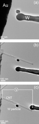
The experiments were performed in a 300 kV JEOL 3100FEF TEM (Omega Filter) equipped with a ‘Nanofactory Instruments’ TEM-STM holder. The vacuum level in the TEM column was about ∼10−5 Pa. CNTs used in this work were synthesized by an arc-discharge method. They were supported in the TEM–STM setup by a gold wire. The wire was dipped into a CNT powder, and then mounted on a fixed terminal of the TEM–STM holder. A chemically etched W tip with a diameter smaller than 50 nm was attached to another terminal of the holder that could be moved in three dimensions with a piezo drive. Clean, unoxidized W particles were produced in situ: the W tip was moved to make physical contact with the edge of a gold wire that was biased to about 1 V. At the moment of contact, the W tip was locally melted by the Joule heating and/or an arc-discharge, and a clean W particle adhered to the W tip (figure (a)). This particle was then transferred to the middle of a CNT, which was protruding from the edge of the Au wire, by delicate in-situ manipulations with a precision better than 1 nm (figure (b)). Finally, the CNT was placed between the Au wire and the W tip and heated by passing an electric current through it (figure (c)). The behavior of the W particle was observed using a CCD camera while gradually increasing the current, and thus, the CNT temperature. A relatively large particle of about 60 nm diameter was used to avoid size effects and ensure that the melting point of the particle is close to that of bulk W.
Figure 1 TEM images showing in situ sample preparation: (a) fabrication of a W particle, (b) placement with a W tip of the particle produced in (a) on a CNT attached to a gold wire, (c) contacting the CNT with the W tip and applying bias voltage to the CNT.
Results and discussion
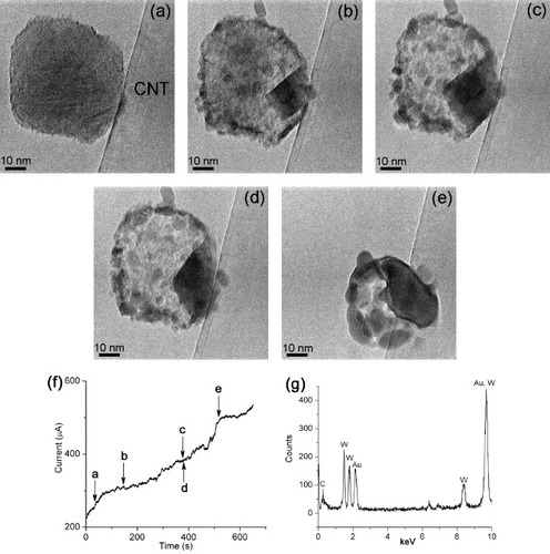
Figure shows the dynamic behavior of a 60-nm-diameter W particle on the surface of a CNT (60 nm diameter) when the electric current, and thus the CNT temperature, was gradually increased as shown in figure (f). Figure (g) is an energy dispersive x-ray spectrum taken from the particle that contains W, Au and C signals. The Au signal originates from the gold wire and the C signal from the supporting CNT. Figures (a)–(e) show progressive spreading of a hill-shaped dark region from the particle/CNT interface into the particle body (see also video 1 in Supplementary data available from stacks.iop.org/STAM/12/044605/mmedia). In contrast to the rough surface of the original particle, the newly formed zone had a smooth contour, and finally spread to almost the entire circumference of the particle when the electric current reached ∼490 μA (figures (e) and (f)). Then, the particle rapidly changed its shape and resembled a fluid. Therefore, we attribute the spreading of the dark zone to the gradual melting of the particle.
Figure 2 (a)–(e) Sequential images captured from a video (video 1 in Supplementary data available from stacks.iop.org/STAM/12/044605/mmedia) showing gradual melting of a W particle heated on the CNT. (f) Time evolution of the electric current passing through the CNT indicating the moments when images (a)–(e) were recorded. (g) Energy dispersive x-ray spectrum taken from the particle shown in (a)–(e).
The electron diffraction patterns of another tungsten particle anchored on a hot CNT were recorded while increasing its temperature (see figure and video 2 in Supplementary data). The observed rapid changes in the diffraction pattern of figures (a)–(c) can be attributed to the variation of the particle shape/morphology and its lattice orientation. They imply that the particle is in a quasi-molten state [Citation4, Citation14–16] and is continuously transforming between different states/structures at a temperature just below the melting point [Citation14, Citation15]. Figures (d)–(f) show the diffraction patterns when the temperature was further increased. Five diffraction spots (1–5) are circled and numbered in these patterns. Spots 3–5 gradually blur and disappear, whereas there is no change in the position and brightness of spots 1 and 2. The disappearance of spots 3–5 reflects partial melting of the particle, as shown in figure .
Figure 3 Diffraction patterns captured from a video (video 2 in Supplementary data available from stacks.iop.org/STAM/12/044605/mmedia) showing partial melting of a W particle heated on the CNT. (a)–(c) Patterns recorded with a period of 1 s showing rapid changes in diffraction patterns. (d)–(f) Patterns captured upon a further increase in temperature. Spots 1 and 2 correspond to a lattice spacing of 0.22 nm, in good agreement with the (110) atomic plane separation in tungsten. Also present are rings originating from the front and back parts of the CNT walls and sharp spots related to the CNT sidewalls.
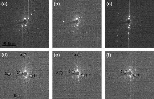
Figure indicates that the melting started at the particle/CNT interface and gradually propagated into the particle body. This is reasonable because the thermal radiation created a temperature gradient within the particle, and the interface was the hottest zone with a temperature equal to that of the CNT. However, the particle did not completely melt, as shown in figures and , which can be attributed to the following two possible reasons. Firstly, the temperature of CNT did not reach the melting point of the tungsten particle and only induced its premelting [Citation13, Citation17, Citation18], with only surface melting. Secondly, although the surface CNT temperature reached the melting point of the tungsten particle, thermal radiation and poor thermal conductance at the particle/CNT interface (probably due to the small contact area) resulted in a temperature gradient within the particle; therefore, only the volume near the interface reached the melting point. The latter explanation agrees well with figures (b)–(d), where the melting zone originated at the particle/CNT interface and then gradually propagated into the particle. Thus, we can conclude that a temperature corresponding to the melting point of the W particle was reached at the interface and the CNT did withstand such heating. To estimate this temperature, we used a phenomenological formula [Citation19] relating the melting point Tm of a W particle with its diameter R as Tm(R)=T∗(1−R1/R), where T∗ is the melting point of bulk tungsten and Rl=2.2 nm is a fitting parameter [Citation19]. Using the values of R=30 nm and T∗∼3700 K [Citation12], we obtain Tm∼3400 K. This temperature of CNT up to which it is stable is much higher than those reported previously [Citation7, Citation9] and is close to the theoretical limit [Citation10].
Before the particle was heated, it had a rough surface (figure (a)) typical of amorphous tungsten [Citation20]. When the particle had been heated, the amorphous surface was recrystallized and many small particles, less than 10 nm in diameter, were formed (figures (b)–(d)). Similar to melting, the recrystallization started at the interface and gradually spread over the entire particle. When the temperature was further increased, all the newly formed small particles melted and fused together (figure (e)). During the melting of the W particle, its diameter decreased from ∼60 nm in figure (a) to ∼45 nm in figure (e). This decrease can be attributed to W sublimation and diffusion of W into and/or onto the CNT. Similar to the case of indium particles on heated CNTs, such diffusion might be enhanced by electromigration, because of the high current density that reached ∼108 A cm−2 [Citation21].
Consequently, we could also study the high-temperature interaction kinetics of W particles and hot CNTs, which is important for the synthesis of tungsten carbide, a widely used engineering material with high melting point, hardness and strength. Tungsten carbide is usually prepared by heating a mixture of tungsten and carbon powders [Citation22]. Figure shows the dynamics of C diffusion into a 60-nm-diameter W particle from a CNT with a diameter of 36 nm. Only after the particle has been melted (or premelted), it absorbs some carbon shells (indicated by a white arrow in figure (b)), implying that the diffusion of C into the W particle starts at a high temperature, close to the melting point of the particle (∼3400 K). A similar absorption of CNT shells by a tungsten tip was found to result in the formation of hexagonal α-WC [Citation23]. However, our observation contradicts with some other reports. WC was formed at 1270 K upon heating a W surface coated with amorphous carbon [Citation24], and complete carburization of a nanometer-sized tungsten powder mixed with carbon black to tungsten carbide was found to take place at 1050 °C [Citation22]. The much higher temperature required for the diffusion of C into W particles from CNTs in our experiments may be attributed to the much higher thermal stability of CNTs in vacuum than that of amorphous C.
Figure 4 Sequential images captured from a video (video 3 in Supplementary data available from stacks.iop.org/STAM/12/044605/mmedia) showing the absorption of graphite layers by a melted or premelted W particle: (a) before heating. (b)–(d) After the particle was melted (or premelted), it absorbed some inner shells of the CNT (white arrow in (b)) and started rolling along the CNT, reeling off graphite layers. As indicated by black arrows in (b)–(d), a thin graphite flake grew while the particle was rolling; the flake length is ∼35, 57 and 95 nm in (b), (c) and (d), respectively.
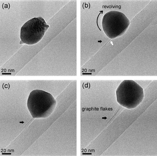
An interesting phenomenon took place during the absorption of graphite layers by the W particle: the particle rolled along the CNT reeling off graphite flakes (see video 3 in Supplementary data available from stacks.iop.org/STAM/12/044605/mmedia). One end of the flakes was anchored to the CNT and the other end was fastened to the moving particle (figures (b)–(d)). The flakes were formed when tube shells had partly been absorbed by the particle and tightly connected to it through some sort of bonding; then, the particle movement caused the flakes to grow. The growth can be understood as follows. The temperature of the system is sufficiently high for the fast W–C intradiffusion. Rolling of the particle increases tension in the flakes, which is reduced through the flake growth, a process similar to reeling off silk from cocoons. In this way, ultrathin graphene-like nanoribbons can be reeled off a CNT. The driving force for the particle movement is not fully understood at this stage. It could be an electromigration force, which was a possible cause of the iron particle movement in the hollow core of CNTs [Citation25]. In figure (d), but not in figures (b) and (c), the particle is shaped as a faceted polyhedron. This means that the particle crystallized while rolling, which reduced the efficiency of the heat transfer from the CNT, and thus, the particle temperature. Finally, we note that the electric current passing through the CNT was stable while the state of the particle was changing.
Conclusions
Tungsten particles were used to probe the local temperature of multiwalled CNTs heated by electric current in vacuum of a transmission electron microscope equipped with a scanning tunneling microscope unit. The CNTs were stable up to the melting point of W particles, which was estimated as 3400 K from their diameter, and thus, the degradation temperature of the CNTs is higher. This result suggests that CNT-based devices can operate at high temperatures in vacuum and that CNTs can be used as nanoscale heaters to obtain the extremely high temperatures. Dynamics of W particles on a hot CNT, including particle crystallization, quasimelting, melting, sublimation and C–W intradiffusion, were observed in real time. The temperature required for the diffusion of C from CNTs into W particles was found to be close to the melting point of W particles. Graphite flakes were reeled off CNTs when melted or premelted W particles rolled along the tube axis that provides a novel in-situ method of producing clean graphene nanoribbons.
Acknowledgment
This work was supported by the International Center for Materials Nanoarchitectonics (MANA) of the National Institute for Materials Science (NIMS).
References
- JongeN DLamyYSchootsKOosterkampT H 2002 Nature 420 393 http://dx.doi.org/10.1038/nature01233
- TansS JVerschuerenA R MDekkerC 1998 Nature 393 49 http://dx.doi.org/10.1038/29954
- LiangX LWangSWeiX LDingLZhuY ZZhangZ YChenQLiYZhangJPengL M 2009 Adv. Mater. 21 1339 http://dx.doi.org/10.1002/adma.v21:13
- HuangJ Y 2007 Nano Lett. 7 2335 http://dx.doi.org/10.1021/nl0709975
- HuangJ YChenSRenZ FChenGDresselhausM S 2006 Nano Lett. 6 1699 http://dx.doi.org/10.1021/nl0609910
- JensenKMickelsonWHanWZettlA 2005 Appl. Phys. Lett. 86 173107 http://dx.doi.org/10.1063/1.1920427
- CaiX YAkitaSNakayamaY 2004 Thin Solid Films 464–465 364 http://dx.doi.org/10.1016/j.tsf.2004.06.061
- KimY AMuramatsuHHayashiTEndoMTerronesMDresselhausM S 2004 Chem. Phys. Lett. 398 87 http://dx.doi.org/10.1016/j.cplett.2004.09.024
- BegtrupG ERayK GKesslerB MYuzvinskyT DGarciaHZettlA 2007 Phys. Rev. Lett. 99 155901 http://dx.doi.org/10.1103/PhysRevLett.99.155901
- MiyamotoYBerberSYoonMRubioATomanekD 2002 Physica B 323 78 http://dx.doi.org/10.1016/S0921-4526(02)00988-2
- ChenSHuangJ YWangZKempaKChenGRenZ F 2005 Appl. Phys. Lett. 87 263107 http://dx.doi.org/10.1063/1.2155116
- GustafsonP 1985 Int. J. Thermophys. 6 395 http://dx.doi.org/10.1007/BF00500270
- BalettoFFerrandoR 2005 Rev. Mod. Phys. 77 371 http://dx.doi.org/10.1103/RevModPhys.77.371
- AjayanP MMarksL D 1988 Phys. Rev. Lett. 60 585 http://dx.doi.org/10.1103/PhysRevLett.60.585
- IijimaSIchihashiT 1986 Phys. Rev. Lett. 56 616 http://dx.doi.org/10.1103/PhysRevLett.56.616
- JinC HSuenagaKIijimaS 2008 Nat. Nanotechnol. 3 17 http://dx.doi.org/10.1038/nnano.2007.406
- PetersK FChungY WCohenJ B 1997 Appl. Phys. Lett. 71 2391 http://dx.doi.org/10.1063/1.120038
- ZhaoS JWangS QChengD YYeH Q 2001 J. Phys. Chem. B 105 12857 http://dx.doi.org/10.1021/jp012638i
- MoitraAKimSHouzeJJelinekBKimS GParkS JGermanR MHorstemeyerM F 2008 J. Phys. D: Appl. Phys. 41 185406 http://dx.doi.org/10.1088/0022-3727/41/18/185406
- XieF YGongLLiuXChenJXieW GZhangW HChenS H 2009 Appl. Surf. Sci. 256 693 http://dx.doi.org/10.1016/j.apsusc.2009.08.044
- ReganB CAloniSRitchieR ODahmenUZettlA 2004 Nature 428 924 http://dx.doi.org/10.1038/nature02496
- JiLTaoLGuoZ MJiaC C 2007 Mater. Sci. Forum 534–536 165 http://dx.doi.org/10.4028/www.scientific.net/MSF.534-536
- WangM SGolbergDBandoY 2010 Adv. Mater. 22 93 http://dx.doi.org/10.1002/adma.v22:1
- LuthinJLinsmeierCh 2000 Surf. Sci. 464–456 78 http://dx.doi.org/10.1016/S0039-6028(00)00181-3
- SvenssonKOlinHOlssonE 2004 Phys. Rev. Lett. 93 145901 http://dx.doi.org/10.1103/PhysRevLett.93.145901