Abstract
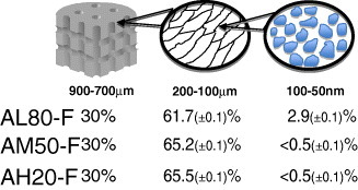
Hydrogels (gellan or agarose) reinforced with nanocrystalline carbonated hydroxyapatite (nCHA) were prepared by the GELPOR3D technique. This simple method is characterized by compositional flexibility; it does not require expensive equipment, thermal treatment, or aggressive or toxic solvents, and yields a three-dimensional (3D) network of interconnected pores 300–900 μm in size. In addition, an interconnected porosity is generated, yielding a hierarchical porous architecture from the macro to the molecular scale. This porosity depends on both the drying/preservation technology (freeze drying or oven drying at 37 ○C) and on the content and microstructure of the reinforcing ceramic. For freeze-dried samples, the porosities were approximately 30, 66 and below 3% for pore sizes of 600–900 μm, 100–200 μm and 50–100 nm, respectively. The pore structure depends much on the ceramic content, so that higher contents lead to the disappearance of the characteristic honeycomb structure observed in low-ceramic scaffolds and to a lower fraction of the 100–200-μm-sized pores. The nature of the hydrogel did not affect the pore size distribution but was crucial for the behavior of the scaffolds in a hydrated medium: gellan-containing scaffolds showed a higher swelling degree owing to the presence of more hydrophilic groups.
Introduction
Tissue engineering has become ‘an interdisciplinary field in which the principles of engineering and the life sciences are applied toward the generation of biological substitutes aimed at the creation, preservation or restoration of lost organ functions’ [Citation1]. More recently, Williams has defined tissue engineering as ‘the creation (or formation) of new tissue for the therapeutic reconstruction of the human body, by the deliberate and controlled stimulation of selected target cells through a systematic combination of molecular and mechanical signals’ [Citation2]. Although no biomaterial is mentioned in these definitions, tissue engineering does need a biomaterial as a framework for single cells to build a vital and well-functioning tissue [Citation3]. These scaffolds act as an extracellular matrix whose three-dimensional architecture organizes the cells, directing the growth and formation of a desired tissue [Citation4], and facilitates the delivery of molecular and mechanical signals [Citation5].
This 3D architecture should include a hierarchical porosity ranging from the nanometer to the millimeter scale [Citation6–8]. These different pore size domains affect such processes as vascularization, which ensures the transport of oxygen, nutrients and waste, and migration of different cell populations, which is necessary for cell survival and an adequate implant-tissue attachment [Citation3, Citation9, Citation10].
The current trend in tissue engineering revolves around the implantation of 3D macroporous scaffolds, which function as templates for cellular activities to provide initial attachment and subsequent regeneration of damaged or lost tissues [Citation11]. Nature shows several examples of lightweight, high-performance structural materials with outstanding strength and toughness [Citation12]. In this sense, biology has long developed the ability to combine brittle minerals and organic molecules into hybrid composites with exceptional fracture resistance and structural capability [Citation13–17].
Unfortunately, these complex structures are extremely difficult to replicate in a controlled manner. In the case of hard tissue substitution, a reasonable strategy is to design ceramic-polymer materials that combine the strength of single components and minimize undesirable drawbacks [Citation18–26]. Bioceramics, such as hydroxyapatite, bioactive glass and tricalcium phosphate, impart high biocompatibility and the ability to induce bone formation while mechanically reinforcing the scaffolds [Citation27–30]. In contrast, natural and synthetic hydrogels mimic the extracellular matrix owing to their high water content and chemical similarity. In addition to their use as scaffolds or bioreactors, reinforced hydrogels that can endure significant mechanical loads are expanding their potential application in drug delivery systems, actuators and artificial muscles, sensors and conductors, photoresponsive gels, cosmetics and food applications [Citation31–39]. The two hydrogels employed in this work to fabricate the scaffolds, agarose [Citation40–42] and gellan [Citation43–46], besides their traditional uses, have recently gained a new appreciation in the biomaterials and drug delivery research fields.
The organization of these components in a hierarchical architecture and the resulting porosity are critical for mechanical performance and optimal integration. In addition, the preservation and manipulation of freshly prepared scaffolds determine whether or not the material can withstand real applications such as surgical implantation or cell seeding.
Freeze drying is being employed as a preservation technology, which enables conservation and ‘off the shelf ’ availability of engineered scaffolds [Citation47–49] and tissues, [Citation50] and as a synthetic route for the construction of complex composites [Citation13, Citation51]. Cryogenic processes consist of freezing, storage in the frozen state and defrosting of low- or high-molecular-weight precursors or colloid systems, all of which are capable of gelling [Citation52, Citation53]. The thus-obtained materials, named cryogels, have been described as macroporous structures with ‘walls’ of matter enclosing empty areas where ice crystals originally resided. They have several applications such as bioseparation, immobilization of biomolecules and as carriers for cell immobilization [Citation54, Citation55]. Many of these applications are based on a network of unidirectional channels, whose size can be tailored to allow unhindered diffusion of solutes of practically any size, as well as mass transport of nano- and even microparticles [Citation56–58]. In addition, the presence of these macropores significantly enhanced the initial cell seeding distribution through the scaffold depth while maintaining a relatively high seeding efficiency [Citation59].
The shaping technology GELPOR3D utilized in this work involves solidification of a suspension with a significant ceramic component (80 wt% for some of the calcium phosphate-based compositions investigated). Consolidation was achieved inside a mold using a thermogelling agent, such as agarose or gellan, which can gel at physiological temperatures. To obtain interconnected macroporous fragments, the solidification was carried out using a network of filaments designed to ensure interconnected porosity in three spatial directions. The network of filaments directing this structure can be easily extracted at room temperature without the use of aggressive solvents. The diameter and arrangement of these filaments determine the pore size (300–900 μm) and the resulting porosity (10–40 vol%) [Citation60].
Besides this designed 3D interconnected porosity, additional pore domains can be detected on scaffolds prepared by this technique as a consequence of the channels generated by lyophilization and the spaces left between the ceramic particles. In this work, we aim to determine the effect of the different components and their proportion on the pore size distribution and porosity and how these two parameters relate to the scaffold structure. The polymer/ceramic ratio is the most important parameter controlling the pore architecture. The nature of the two gelling agents seems to affect the swelling behavior of these scaffolds in an aqueous medium, but has a much weaker effect on their structure. Very similar results were obtained for the scaffolds prepared with either agarose or gellan, and therefore, they are shown alternately in the figures.
Experimental details
Materials
Nanocrystalline carbonated hydroxyapatite (nCHA) was prepared by precipitation from an aqueous solution of Ca(NO3)24H2O, (NH4)2HPO4 and (NH4)2CO3 (Puriss, Riedel-de-Häen) at 37 ○C [Citation61]. The pH of the solution was maintained at 9.2 by adding an NH4OH solution. The resulting suspension was vacuum-filtered, and the product was freeze-dried. The obtained nCHA powder had a CO32- content of 8.0 ± 0.3% (determined by CHN Elemental Microanalysis) and a high specific surface area of 120 m2 g−1; it was composed of nanocrystals (15–20)×(3–5 nm) in size. We used the following polymers: agarose (Agarose for routine use, Sigma-Aldrich, Steinheim, Germany) and gellan (Gelrite Gellan Gum powder, Sigma-Aldrich, Steinheim, Germany).
Scaffold preparation
Three-dimensional interconnected porous polymer/nCHA scaffolds were fabricated using the shaping process GELPOR3D patented by the authors [Citation60, Citation62]. The fabrication procedure consists of the following steps: the gelling powder is suspended in deionized water and heated to 85 ○C with continuous stirring; once a translucent sol is formed, the temperature is gradually decreased to 40–45 ○C and then a ceramic powder (nCHA) is added under continuous stirring. The obtained slurry is poured into a designed mold containing a network of rigid filaments (1 mm in diameter) that can be removed after 1–2 min. After a few minutes the complete consolidation of the bodies allows the unmolding of the material, which, freshly prepared, can be easily handled and shaped in the desired form. The 3D perforated scaffolds were preserved by different drying procedures: in an oven at 37 ○C and by freeze drying.
Two natural polysaccharides, agarose and gellan, were used as gelling agents for the scaffold fabrication. Perforated scaffolds with different polymer and nCHA contents were prepared (table 1).
Table 1 Nominal compositions of the scaffolds obtained with agarose.
Characterization
The scaffolds were analyzed by x-ray diffraction (XRD) with a Philips X-Pert MPD diffractometer and by scanning electron microscopy (SEM, JEOL 6400). Fourier transform infrared (FTIR) spectra were recorded with a Nicolet Nexus spectrometer equipped with a Smart Golden Gate attenuated total reflection accessory. Thermogravimetry analysis (TGA) was performed with a Perkin Elmer Pyris Diamond TG/DTA system at a heating rate of 10 ○C min−1. Hg intrusion porosimetry measurements were conducted with a Micromeritics AutoPore III 9410 porosimeter. N2 adsorption curves were recorded with a Micromeritics ASAP 2010 instrument; the surface area was calculated by applying the Brunauer–Emmett–Teller (BET) method to the isotherms and the pore size distribution was obtained by the Barrett–Joyner–Halenda (BJH) method from the desorption branch of the isotherm.
The scaffold densities were estimated from the volume, which was evaluated by three techniques: Hg intrusion porosimetry, He picnometry (AccuPyc 1330 Micromeritics) and manual measurement with a micrometer. In the last case, the facets were polished with a 600-grit silicon carbide paper to render them flat and approximately parallel, and the measurements were repeated in three locations along the specimen. The data were averaged over four samples.
Swelling of the scaffolds was studied by immersing weighted desiccated cylinders (10 mm long, 3 mm diameter) into a physiological solution (0.9% NaCl, pH=7.4) at 37 ○C for 24 h. Then, the scaffolds were dried with filter paper and weighed to determine the water uptake.
Results and discussion
One of the main advantages of our preparation method is the possibility of shaping any kind of ceramic without modifying its original texture and microstructure, because the process is carried out at room temperature and in the absence of aggressive or toxic solvents. Other shaping methods of the nanocrystalline carbonated hydroxyapatite may reduce its high surface area (120 m2 g−1), increase the crystal size and dissolve it. This would decrease its reactivity and thus osteogenic capacity, thereby affecting the bioactivity of this apatite when implanted in living organisms [Citation63].
Table 1 lists the compositions of the slurries used to prepare the scaffolds, demonstrating the versatility of the GELPOR3D technique. Note that low agarose contents may result in an insufficient interaction between the ceramic particles and polysaccharide binder that may cause particle migration after implantation. On the other hand, slurries with high ceramic loads may be too viscous for pouring into the mould and fill the interstices between the rigid filaments. Scaffolds with a non designed porosity have been prepared at higher ceramic loads [Citation64]. However, even in these cases, the ceramic presence does not affect the gelation process, which is carried out within a few minutes.
Figures and show, respectively, the XRD patterns and FTIR spectra of the GL80-F scaffold prepared by the GELPOR3D method. The XRD patterns are very similar for the scaffold and the nCHA powder, with all the diffraction maxima attributed to a poorly crystallized apatite phase (JCPDS card 24–0033), whereas the amorphous background due to gellan is hardly visible. No significant differences were observed in the XRD patterns of the samples prepared using different types of hydrogel or ceramic/polymer ratios.
Figure 1 XRD patterns of nCHA, GL80-F scaffold and gellan.
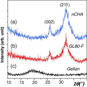
Figure 2 FTIR spectra of nCHA, GL80-F scaffold and gellan.
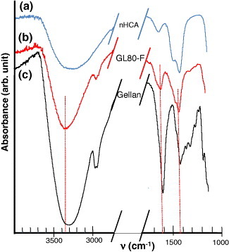
Although the shaped ceramic maintains its nanoscale crystallinity and texture, as demonstrated below, it does not remain inert and interacts with other components in the scaffold. FTIR spectroscopy has been employed to examine the possible interactions between the ceramic component and the gelling agents. Figure compares the spectra of the GL80-F scaffold, pure gellan and nCHA, revealing a weak interaction between the carboxylate and hydroxyl groups of the gellan with the nCHA. In particular, the broad peak at 3317 cm−1 in the gellan, related to the hydroxyl groups of the glucopyranose ring with various degrees of hydrogen bonding [Citation65], is shifted to 3351 cm−1 in the GL80-F scaffold. The bands at 1605 and 1412 cm−1 in the gellan, due to asymmetric and symmetric stretching vibrations of the carboxylate group, appear at 1621 and 1421 cm−1, respectively, in the scaffold; the latter peak interferes with the contribution of the CO32- groups of the ceramic, which has signals at 1474, 1419 and 873 cm−1 [Citation61]. The shift of the hydroxyl band was also observed in agarose-containing scaffolds. A similar interaction between chitosan and a nanohydroxyapatite has been described, where the polymeric component not only served as a matrix but also provided an anchoring site for the ceramic particles [Citation28].
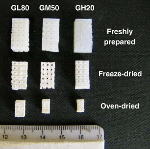
Figure shows the 3D porous scaffolds GH20, GM50 and GL80, obtained from slurries of three different compositions, in a hydrated state and dried by two different methods. The freshly prepared samples (top row) show a rubber like texture and can be easily cut with a knife and shaped by hand. The preservation of these materials was carried out by freeze drying or in an oven at 37 ○C. The freeze drying procedure results in the complete removal of water and a weight loss of 90–95%, as determined by thermogravimetry, but only in a 5–10% volume reduction. Drying in an oven causes a similar weight loss but with a much larger volume change (50–60%), while maintaining the body shape as shown at the bottom row of figure . Scaffolds with higher ceramic content shrink less regardless of the drying procedure, whereas the shrinking is independent of the gelling agent.
Figure 3 Photographs of the GL80, GM50 and GH20 scaffolds.
These clear differences between freeze-dried and oven-dried scaffolds markedly affect the microstructure and texture of the scaffolds. We used SEM to measure the diameter of the bigger pores—those that are generated when the rigid filaments of the mold are removed, yielding a 3D interconnected porosity, and those that are visible to the naked eye (figure ). Such pores have been termed as ‘giant’ by several authors [Citation66] to stress that they are large enough to allow the vascularization of the scaffold.
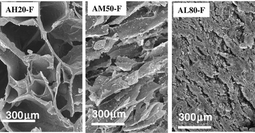
The final size of these giant pores depends on the drying method, and is 600–800 μm for oven drying and 700–900 μm for freeze drying. The spread for a given drying method is related to the ceramic content—the largest contraction is observed in scaffolds with the lowest nCHA contents, which have giant pores with a diameter between 600 and 700 μm depending on the drying method. Figure shows one of these giant pores in an AH20-F scaffold together with another, network like microstructure. This network is characteristic of freeze-dried materials and has been described by several authors as a honeycomb or sponge-like structure. This sponginess can be explained considering the elimination of water from the freshly prepared scaffold. During the freezing process, ice crystals nucleate from the solution and grow along the lines of thermal gradients; the subsequent lyophilization generates a porous material [Citation67]. This type of structure, with 100–200-μm-sized pores, is clearly observed in freeze-dried scaffolds with low ceramic contents (figure ). This characteristic honeycomb-like structure progressively transforms with increasing ceramic content, yielding a dense, pore-free surface (figure ).
Figure 4 Photograph and SEM image of the AH20-F scaffold.
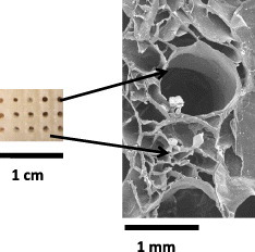
Figure 5 SEM images of the AH20-F, AM50-F and AL80-F scaffolds.
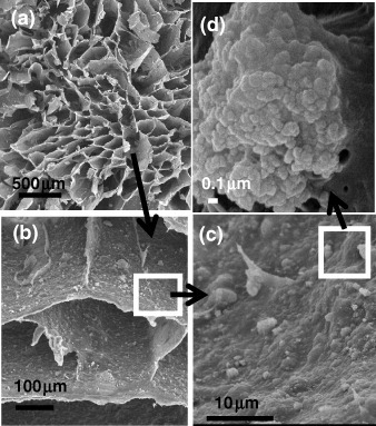
SEM observations (figure ) clarified the physical interaction between the gelling agent and the nCHA particles. In the characteristic honeycomb structure of the polymeric network, a homogeneous distribution of the ceramic within the organic lamella that constitutes the channels (figures (a) and (b)) can be observed. A magnification of one of these walls shows how the particles are embedded in the polymeric matrix (figures (c) and (d)). Higher nCHA contents cause such a thickening of the channels walls, which may result in their partial or total occlusion.
Figure 6 SEM images of the GH20-F scaffold at different magnifications.
The intimate ceramic–polymer interaction can modify the nCHA surface, thereby affecting its dissolution and the ability to generate new bones. However, N2 adsorption porosimetry reveals a progressive decrease in the original surface area of the powdered nanohydroxyapatite from ∼120 to 58 m2 g−1 in AL80-F, 28 m2 g−1 in AM50-F and 12 m2 g−1 in AH20-F, which correlates with the decreasing ceramic content in these scaffolds. In addition, the monomodal pore size distribution peaking around 50–100 nm in the ceramic is maintained in all these scaffolds.
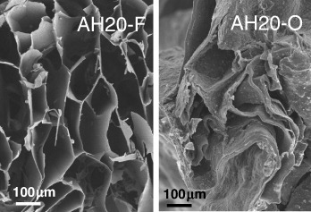
The oven-dried scaffolds show a completely different morphology consisting of a wrinkled collapsed structure (figure ). In this case, the water elimination causes a ceramic-dependent volume reduction and does not lead to the formation of the characteristic honeycomb structure of freeze-dried samples.
Figure 7 SEM images of the AH20-F (freeze-dried) and AH20-O (oven-dried) scaffolds.
Hg intrusion porosimetry and He picnometry have been employed to complement the porosity characterization of the different pore size domains already described. Figure (a), which represents the quantity of Hg adsorbed on each material, allows the quantification of the differences, in terms of porosity, between the scaffolds. Increasing the ceramic contents decreases the adsorption capacity of the scaffolds (figure (a)). Note that the spongy structure of the freeze-dried scaffolds strongly depends on the ceramic content. As shown in figure (b), the GH20-F sample shows the highest Hg adsorption in pores of ∼200 μm size; these pores seem to shrink to ∼100 μm at higher ceramic contents, as can be observed for sample GM50-F, and disappear for sample GL80-F.
Figure 8 (a) Hg cumulative intrusion and (b) pore size distribution of the GH20-F, GM50-F, GM50-O and GL80-F scaffolds and nCHA.
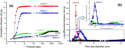
Analysis of the mercury intrusion at higher pressures confirms the presence of a third type of pore with diameters of 50–100 nm (figure (b), inset) detected by N2 adsorption porosimetry. These pores can be clearly observed in the sample with the highest ceramic content (GL80-F), which shows a very similar adsorption curve to that of the powdered nCHA, indicating that these pores are the spaces left by the ceramic particles. This type of pore is hardly detectable in samples GM50-F and GH20-F owing to their lower ceramic content and strong low-pressure signals (figure (a)). This inobservation can be explained as follows: the low ceramic/polymer ratio implies a thorough polymer coating of each ceramic particle, which destroys pores present at the interparticle areas in the original material.
Figure (a) contains the Hg adsorption curve of a GM50-O sample to illustrate the difference between the oven-dried and lyophilized scaffolds, namely, the absence of 100–200-μm-sized pores in the GM50-O scaffold, which are otherwise generated following the water extraction during the freeze-drying procedure. To understand this difference, as well as the effect of the composition on the microstructure of the obtained scaffolds, their densities were measured by three methods. The bulk (also known as envelope) density indicates the volume resulting from close-fitting imaginary envelopes completely surrounding each scaffold (ASTM D3766 standard). This volume was determined by two methods: manual measurement with a micrometer (density dg) and by Hg intrusion porosimetry (density dp). The skeletal (also known as absolute) density dSKE, which indicates the sum of the volumes of the solid material and closed pores within the scaffolds (ASTM D3766), was measured by Hg intrusion porosimetry at high pressures. Finally, the solid (also known as true) density dSOL, which excludes open and closed pores (British Standard Institute), was evaluated with He picnometry.
Similar results were obtained for scaffolds prepared from gellan and agarose, and therefore, table 2 lists only the densities of agarose scaffolds. No significant difference is observed between the bulk densities measured manually or by Hg intrusion porosimetry, in agreement with a previous study [Citation68]. All the densities of freeze-dried samples increase with the ceramic content. The considerable volume reduction resulted in higher bulk densities in oven-dried than in freeze-dried scaffolds, and these densities decrease with the ceramic content. The higher values of dSKE and dSOL than the bulk densities (dg or dp) can be explained by the different measured volumes. We also note the difficulties in the Hg intrusion porosimetry analysis of samples with the lowest ceramic content, as their collapsed structure hindered the penetration of mercury inside the dried scaffolds.
Table 2 Bulk, skeletal and solid densities and porosities of lyophilized and oven-dried agarose scaffolds.
Two types of porosity values, PSKE and PSOL, were calculated with equation (1) [Citation69]; the bulk densities dg were placed in the numerator (d1) and the skeletal (dSKE) or solid (dSOL) densities in the denominator (d2).
Similar porosities of over 90% were calculated for all lyophilized scaffolds; these high values can be explained considering that the water content of the freshly prepared scaffolds varied between 88.1 and 93.30% (table 1). For samples M50-F and H20-F, regardless of the gelling agent, the porosity values relate to the amount of water eliminated during preservation. However, the sample with the highest ceramic content shows a considerable difference between the calculated porosities (92–94%) and the water percentage determined by thermogravimetry (88%). This additional porosity can be justified considering the pores left among the ceramic particles, and these pores have been observed by N2 adsorption and Hg intrusion porosimetries. The latter technique allowed us the estimation of this interparticle porosity as 30–40% of the total porosity.
The calculated porosities were lower for oven-dried than for lyophilized scaffolds in all the cases, probably because the water elimination led to a considerable shrinkage, which increased with the polymer content, and did not create the 100–200 μm channels.
To summarize and clarify the pore characterization results, the estimated percentages of different pore size domains for lyophilized scaffolds are presented in figure . The ‘giant’ pore content (∼30%) relates to the amount of filaments employed to prepare the scaffolds. As previously established [Citation60], the GELPOR3D method yields porosities of 10–40%, depending on the size of the filaments and their arrangement. The remaining porosity (70%) corresponds to the pores within the solid skeleton of the scaffold, and most of it can be related to water elimination. In the case of lyophilized scaffolds, the porosity values are equal to or greater than the water content, determined by thermogravimetry. In scaffolds with the highest ceramic content the porosity can be related to the pores generated between the ceramic particles or within them; this has been estimated by Hg intrusion porosimetry. The presence of this type of porosity cannot be ruled out in other samples. A close examination of the pore size distributions obtained by Hg intrusion porosimetry reveals a weak maximum in the corresponding region, but its quantification yielded impractical values below 1%. As for oven-dried samples, their porosities were difficult to estimate because of the considerable volume shrinkage and unreliable Hg-intrusion porosimetry results.
Figure 9 Porosities of the different pore size domains in freeze-dried scaffolds.
The behavior of these reinforced hydrogels in hydrated media is of critical importance for all potential applications. The swelling behavior is intimately related to the fluid intake and, consequently, with the material porosity. Therefore, the different factors that affect porosity, such as the ceramic content and the preservation procedure, should affect the hydration rate and the final swelling degree. In addition, the nature of the polymer is responsible for the hydrogel behavior and determines the transition from the glassy structure in the dehydrated state to the formation of elastic gels. This behavior is attributed to the polymer component because, owing to the hydrophilic nature of its chains, the network can absorb water within its structure, swell without destruction, and maintain its overall structure [Citation70].
Figure depicts the final swelling degree of the 3D scaffolds in terms of water uptake, which was calculated from the gravimetry data as
Figure 10 Water uptake of some 3D scaffolds after 24 h averaged over four measurements.
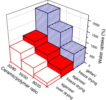
Here, Wi corresponds to the weight of the desiccated samples and Wt to the weight after swelling.
The capability of these scaffolds to adsorb fluids several times their own weight can be explained considering these materials as ceramic-reinforced hydrogels. Their swelling degree decreases with the nCHA content. A similar trend in water absorption has been reported for nCHA/chitosan [Citation28] and β-TCP/agarose composites [Citation64], indicating that the addition of ceramic decreases the water absorption. Not only the quantity but also the nature of the polymer affects the swelling degree: the water uptake is higher for scaffolds prepared with gellan than with agarose because of the more hydrophilic character of gellan. Finally, the scaffolds dried in an oven shrink more and absorb less water than freeze-dried scaffolds. This fact can be related with the higher porosity of lyophilized systems, and it has been observed in other scaffolds [Citation42].
While swelling, the scaffolds increase their volume, by 20–40% for lyophilized samples containing agarose, 25–50% for samples containing gellan and more than 100% for oven-dried scaffolds. This capability to quickly rehydrate in the presence of any aqueous solution such as plasma or blood should facilitate the surgical applications of the scaffolds; it should also increase the biomineralization in the cell culture medium [Citation71]. Finally, the fixation of the scaffold within the defect to be repaired is improved by swelling, which also ensures a constant pressure and an intimate contact stimulating bone regeneration.
Conclusions
Preservation techniques (freeze or oven drying) and the ceramic/polymer ratio have a critical effect on the pore architecture of the nCHA-gellan and nCHA-agarose scaffolds obtained by the GELPOR3D method. In this work, the interconnected porosity was designed to have 900 μm ‘giant’ pores, which yield a 30% porosity or void space. The porosity within the ceramic–polymer material that constitutes the scaffold has been characterized and quantified. Lyophilized scaffolds have two pore-size domains. One is parallel channels with diameters between 100 and 200 μm depending on the ceramic content, which can be attributed to the extraction of ice crystals during the freeze drying procedure. The other pore size distribution, centered between 50 and 100 nm, depends on the ceramic microstructure. Despite their small total volume, these pores may be important for the migration of fluids from or to the cells or for the controlled release of bioactive molecules. Oven-dried scaffolds are characterized by two types of pore: ceramic-dependent nanosized pores and a tunable network of interconnected giant pores. The hydration behavior of the preserved scaffolds depends on both the pore hierarchy and nature of the hydrogel, i.e. the more hydrophilic structure of gellan than of agarose results in a higher swelling degree in terms of weight and volume.
Acknowledgments
This work was supported by CICYT, Spain (Project MAT2008-00736) and by the Comunidad de Madrid, Spain (S2009/MAT-1472). The XRD and SEM measurements were performed at C.A.I. Difracción de Rayos X and Microscopia Electrónica (UCM), respectively.
References
- LangerRVacantiJ P 1993 Science 260 920 http://dx.doi.org/10.1126/science.8493529
- WilliamsD F 2009 Biomaterials 30 5897 http://dx.doi.org/10.1016/j.biomaterials.2009.07.027
- EisenbarthE 2007 Adv. Eng. Mater. 9 1051 http://dx.doi.org/10.1002/(ISSN)1527-2648
- YangS FLeongK FDuZ HChuaC K 2001 Tissue Eng. 7 679 http://dx.doi.org/10.1089/107632701753337645
- WillieB MPetersenASchmidt-BleekKCipitriaAMehtaMStrubePLienauJWildemannBFratzlPDudaG 2010 Soft Matter 6 4976 http://dx.doi.org/10.1039/c0sm00262c
- Vallet-RegíM 2008 Chem. Eng. J. 137 1 http://dx.doi.org/10.1016/j.cej.2007.10.015
- HollisterS J 2005 Nat. Mater. 4 518 http://dx.doi.org/10.1038/nmat1421
- Vallet-RegíM 2010 J. Int. Med. 267 22 http://dx.doi.org/10.1111/jim.2009.267.issue-1
- GuobaoWMaP X 2008 Adv. Funct. Mater. 3568
- YuanH PKurashinaKde BruijnJ DLiY Bde GrootKZhangX D 1999 Biomaterials 20 1799 http://dx.doi.org/10.1016/S0142-9612(99)00075-7
- HollisterS J 2009 Adv. Mater. 21 3330 http://dx.doi.org/10.1002/adma.v21:32/33
- HukinsD W LLeahyJ CMathiasK J 1999 J. Mater. Chem. 9 629 http://dx.doi.org/10.1039/a807411i
- LauneyM EMunchEAlsemD HBarthH BSaizETomsiaA PRitchieR O 2009 Acta Mater. 57 2919 http://dx.doi.org/10.1016/j.actamat.2009.03.003
- MunchELauneyM EAlsemD HSaizETomsiaA PRitchieR O 2008 Science 322 1516 http://dx.doi.org/10.1126/science.1164865
- HuebschNMooneyD J 2009 Nature 462 426 http://dx.doi.org/10.1038/nature08601
- Vallet-RegíMColillaMGonzálezB 2011 Chem. Soc. Rev. 40 596 http://dx.doi.org/10.1039/c0cs00025f
- SundarSKunduJKunduS C 2010 Sci. Technol. Adv. Mater. 11 014104 http://dx.doi.org/10.1088/1468-6996/11/1/014104
- Vallet-RegíM 2006 Dalton Trans. 5211
- RamakrishnaSMayerJWintermantelELeongK W 2001 Compos. Sci. Technol. 61 1189 http://dx.doi.org/10.1016/S0266-3538(00)00241-4
- BarrereFMahmoodT Ade GrootKvan BlitterswijkC A 2008 Mater. Sci. Eng. R—Rep. 59 38 http://dx.doi.org/10.1016/j.mser.2007.12.001
- HingK A 2004 Philos. Trans. R. Soc. Lond. A 362 2821 http://dx.doi.org/10.1098/rsta.2004.1466
- Vallet-RegíM 2010 C. R. Chim. 13 174 http://dx.doi.org/10.1016/j.crci.2009.03.004
- Sánchez-SalcedoSNietoAVallet-RegíM 2008 Chem. Eng. J. 137 62 http://dx.doi.org/10.1016/j.cej.2007.09.011
- JuhaszJ ABestS MBonfieldW 2010 Sci. Technol. Adv. Mater. 11 014103 http://dx.doi.org/10.1088/1468-6996/11/1/014103
- FuruichiKOakiYIchimiyaHKomotoriJImaiH 2006 Sci. Technol. Adv. Mater. 7 219 http://dx.doi.org/10.1016/j.stam.2005.10.008
- CabañasM VPeñaJRománJVallet-RegíM 2006 J. Biomed. Mater. Res. Part A 78A 508 http://dx.doi.org/10.1002/(ISSN)1552-4965
- Vallet-RegíMGonzález-CalbetJ M 2004 Prog. Solid State Chem. 32 1 http://dx.doi.org/10.1016/j.progsolidstchem.2004.07.001
- Thein-HanW WMisraR D K 2009 Acta Biomater. 5 1182 http://dx.doi.org/10.1016/j.actbio.2008.11.025
- SopyanIMelMRameshSKhalidK A 2007 Sci. Technol. Adv. Mater. 8 116 http://dx.doi.org/10.1016/j.stam.2006.11.017
- ZhangL LHanagataNMaedaMMinowaTIkomaTFanHZhangX D 2009 Sci. Technol. Adv. Mater. 10 025003 http://dx.doi.org/10.1088/1468-6996/10/2/025003
- LeeK YMooneyD J 2001 Chem. Rev. 101 1869 http://dx.doi.org/10.1021/cr000108x
- PeppasN AHiltJ ZKhademhosseiniALangerR 2006 Adv. Mater. 18 1345 http://dx.doi.org/10.1002/(ISSN)1521-4095
- SchmidtJ JRowleyJKongH J 2008 J. Biomed. Mater. Res. A 87 1113
- Van TommeS RStormGHenninkW E 2008 Int. J. Pharm. 355 1 http://dx.doi.org/10.1016/j.ijpharm.2008.01.057
- KloudaLMikosA G 2008 Eur. J. Pharm. Biopharm. 68 34 http://dx.doi.org/10.1016/j.ejpb.2007.02.025
- SlaughterB VKhurshidS SFisherO ZKhademhosseiniAPeppasN A 2009 Adv. Mater. 21 3307 http://dx.doi.org/10.1002/adma.v21:32/33
- CalvertP 2009 Adv. Mater. 21 743 http://dx.doi.org/10.1002/adma.v21:7
- LutolfM P 2009 Nat. Mater. 8 451 http://dx.doi.org/10.1038/nmat2458
- AnnabiNNicholJ WZhongXJiC DKoshySKhademhosseiniADehghaniF 2010 Tissue Eng. B 16 371 http://dx.doi.org/10.1089/ten.teb.2009.0639
- RinaudoM 2008 Polym. Int. 57 397 http://dx.doi.org/10.1002/(ISSN)1097-0126
- TabataMShimodaTSugiharaKOgomiDSerizawaTAkashiM 2003 J. Biomed. Mater. Res. B 67 680 http://dx.doi.org/10.1002/(ISSN)1097-4636
- CabañasM VPeñaJRománJVallet-RegíM 2009 Eur. J. Pharm. Sci. 37 249 http://dx.doi.org/10.1016/j.ejps.2009.02.011
- FialhoA MMoreiraL MGranjaA TPopescuA OHoffmannKSa-CorreiaI 2008 Appl. Microbiol. Biotechnol. 79 889 http://dx.doi.org/10.1007/s00253-008-1496-0
- GongY HWangC MLaiR CSuKZhangFWangD A 2009 J. Mater. Chem. 19 1968 http://dx.doi.org/10.1039/b818090c
- OliveiraJ TMartinsLPicciochiRMalafayaI BSousaR ANevesN MManoJ FReisR L 2010 J. Biomed. Mater. Res. A 93 852
- SmithA MSheltonR MPerrieYHarrisJ J 2007 J. Biomater. Appl. 22 241 http://dx.doi.org/10.1177/0885328207076522
- HoM-HKuoP-YHsiehH-JHsienT-YHouL-TLaiJ-YWangD-M 2004 Biomaterials 25 129 http://dx.doi.org/10.1016/S0142-9612(03)00483-6
- ZmoraSGlicklisRCohenS 2002 Biomaterials 23 4087 http://dx.doi.org/10.1016/S0142-9612(02)00146-1
- LandiEValentiniFTampieriA 2008 Acta Biomater. 4 1620 http://dx.doi.org/10.1016/j.actbio.2008.05.023
- PancrazioJ JWangFKelleyC A 2007 Biosens. Bioelectron. 22 2803 http://dx.doi.org/10.1016/j.bios.2006.12.023
- DevilleSSaizENallaR KTomsiaA P 2006 Science 311 515 http://dx.doi.org/10.1126/science.1120937
- GutierrezM CFerrerM LdelMonteF 2008 Chem. Mater. 20 634 http://dx.doi.org/10.1021/cm702028z
- LozinskyV IGalaevI YPlievaF MSavinaI NJungvidHMattiassonB 2003 Trends Biotechnol. 21 445 http://dx.doi.org/10.1016/j.tibtech.2003.08.002
- PlievaF MGalaevI YNoppeWMattiassonB 2008 Trends Microbiol. 16 543 http://dx.doi.org/10.1016/j.tim.2008.08.005
- LozinskyV IPlievaF MGalaevI YMattiassonB 2001 Bioseparation 10 163 http://dx.doi.org/10.1023/A:1016386902611
- WegstU G KSchecterMDoniusA EHungerP M 2010 Philos. Trans. R. Soc. A 368 2099 http://dx.doi.org/10.1098/rsta.2010.0014
- MallickK K 2009 J. Am. Ceram . Soc. 92 S85 http://dx.doi.org/10.1111/jace.2009.92.issue-s1
- QianLAhmedAFosterARannardS PCooperA IZhangH F 2009 J. Mater. Chem. 19 5212 http://dx.doi.org/10.1039/b903461g
- BuckleyC TO'KellyK U 2010 J. Biomed. Mater. Res. B 93 459
- PeñaJRománJCabañasM VVallet-RegíM 2010 Acta Biomater. 6 1288 http://dx.doi.org/10.1016/j.actbio.2009.10.049
- PadillaSIzquierdo-BarbaIVallet-RegíM 2008 Chem. Mater. 20 5942 http://dx.doi.org/10.1021/cm801626k
- Vallet-RegiMPeña LópezJRomán ZaragozaJCabañas CriadoM V 2010 Método para la preparación a baja temperatura de piezas de biocerámicas con porosidad tridimensional diseñada e interconectad Spain. ES2333851
- AlcaideMSerranoM-CRománJCabañasM-VPeñaJSánchez-ZapardielEVallet-RegíMPortolésM-T 2010 J. Biomed. Mater. Res. A 95 793
- RománJCabañasM VPeñaJDoadrioJ CVallet-RegíM 2008 J. Biomed. Mater. Res. A 84 99
- AgnihotriS AJawalkarS SAminabhaviT M 2006 Eur. J. Pharm. Biopharm. 63 249 http://dx.doi.org/10.1016/j.ejpb.2005.12.008
- YunH SKimS EHyunY THeoS JShinJ W 2007 Chem. Mater. 19 6363 http://dx.doi.org/10.1021/cm7023923
- Francis SuhJ KMatthewH W T 2000 Biomaterials 21 2589 http://dx.doi.org/10.1016/S0142-9612(00)00126-5
- XuH H KQuinnJ BTakagiSChowL CEichmillerF C 2001 J. Biomed. Mater. Res. 57 457 http://dx.doi.org/10.1002/(ISSN)1097-4636
- KarageorgiouVKaplanD 2005 Biomaterials 26 5474 http://dx.doi.org/10.1016/j.biomaterials.2005.02.002
- MorrisV JBrownseyG JChilversG RHarrisJ EGunningA PRidoutM JStevensB J H 1990 Carbohydr. Polym. 13 165 http://dx.doi.org/10.1016/0144-8617(90)90082-4
- MadhumathiKKumarP T SKavyaK CFuruikeTTamuraHNairS VJayakumarR 2009 Int. J. Biol. Macromol. 45 289 http://dx.doi.org/10.1016/j.ijbiomac.2009.06.009