Abstract
The water-cooled thermomechanical control process (TMCP) is a technology for improving the strength and toughness of water-cooled steel plates, while allowing control of the microstructure, phase transformation and rolling. This review describes metallurgical aspects of the microalloying of steel, such as niobium addition, and discusses advantages of TMCP, for example, in terms of weldability, which is reduced upon alloying. Other covered topics include the development of equipment, distortions in steel plates, peripheral technologies such as steel making and casting, and theoretical modeling, as well as the history of property control in steel plate production and some early TMCP technologies. We provide some of the latest examples of applications of TMCP steel in various industries such as shipbuilding, offshore structures, building construction, bridges, pipelines, penstocks and cryogenic tanks. This review also introduces high heat-affected-zone toughness technologies, wherein the microstructure of steel is improved by the addition of fine particles of magnesium-containing sulfides and magnesium- or calcium-containing oxides. We demonstrate that thanks to ongoing developments TMCP has the potential to meet the ever-increasing demands of steel plates.
Introduction
The recent increase in the demand for steel structures and the increased severity in service conditions have promoted the development of technologies for many types of microstructural control, which has enabled improvements in alloy design [Citation1]. The water-cooled thermomechanical control process (TMCP) allows microstructural evaluation with rolling and phase transformation control of water-cooled materials. This process has many advantages that can help overcome issues related to the addition of major alloying elements and conventional heat treatments. TMCP steels with added microalloys have been developed to manage the conflicting requirements of strength, toughness and weldability through grain refinement [Citation1–5]. TMCP effectively enables a reduction of the preheating temperature [Citation6], thus lowering the fabrication cost. As TMCP steels afford good weldability, they are highly valued in industries such as shipbuilding, offshore structures, pipelines and building construction. It is anticipated that customers will require even greater strength and toughness as well as new properties, and thus the further development of TMCP is an important issue.
This paper reviews TMCP technologies and their latest developments, starting with a brief overview of the history of material property control technologies in plate manufacturing, some earlier TMCP technologies, and examples of applications of TMCP plates in various industries [Citation7] and their future prospects. It also introduces the high heat-affected-zone (HAZ) toughness technologies of welding, as weldability is crucial for steel products. High-heat-input welding techniques have also been developed to meet the demand for increased productivity. In addition to TMCP, a holistic technical scheme has been developed to satisfy the toughness requirements under high heat-input-conditions [Citation8–12]. High HAZ toughness technology is now well established; it comprehensively includes austenite grain size refinement and intragranular ferrite transformation. These technologies are widely applied to different mass-produced steels and are therefore reviewed in this article.
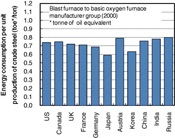
After an exhaustive literature survey, we found that many of the current practical integrated engineering achievements of TMCP were first demonstrated in Japan. This observation can be related to the fact that the energy consumption per unit production of crude steel in Japan is the lowest among the major steelmaking countries (figure ) [Citation13]. The extension of such advanced technology to other parts of world may be beneficial for the global environment. Unfortunately, such developments are not widely reported in academic journals, owing to their emphasis on engineering, and are generally limited to conference proceedings. The authors believe that a systematic review of these achievements will enable the benefits of TMCP to reach a wider audience outside of Japan.
Figure 1 Estimated energy efficiency of blast furnace to basic oxygen furnace steel making in major steel-producing countries in 2000 [Citation13].
Historical review of material property control technologies for plate production
Steel plate property control technologies have been developed to meet the requirements of higher strength and toughness. Stronger and tougher steels have traditionally been produced by conventional alloying or heat treatments. Although alloying improves these properties, it also has some disadvantages, such as increased manufacturing cost and lower weldability. The plate thickness and toughness that can be achieved by alloying are therefore limited.
The history of TMCP has been thoroughly reviewed by Yoshie [Citation1] and Ichikawa et al [Citation14]. The first commercial cooling method was probably the water quenching of reheated plates above their transformation temperature of about 900 °C, which is called reheat quenching. Platen quenching and roller quenching date back to 1935 and 1966, respectively. These heat treatments, which consist of water quenching from elevated temperatures and subsequent heat treatment (tempering) at approximately 600 °C, produce stronger and tougher plates. The reheat quenching process, however, does not consider the cooling rate and simply refers to a method of quenching undeformed austenite as rapidly as possible. The first industrial-scale manufacturing process with online quenching on hot-rolled plates was introduced in 1956 in Japan [Citation1, Citation15]. Since then, there has been massive commercial production of steel plates with tensile strength rated between 600 and 800 MPa. This online quenching procedure for hot-rolled plates involves their directly quenching into water in a tank; it is the prototype of present-day TMCP in that it may result in enhanced strength, toughness and weldability. As illustrated below, TMCP involves the careful optimization of microalloying (e.g. niobium addition) with only small amounts added in each stage of the plate manufacturing process. It is also worth noting that minimizing the use of alloying elements in TMCP is one of the most advantageous features in terms of the weldability of plates. The most fundamental properties required for structural steels are strength and toughness. The crystalline grain size plays the most important role in controlling such properties of steels in terms of yield strength and toughness, which is represented by the ductile-brittle transition temperature. A vast amount of work on the improvement of steel properties has been carried out. Yield strength can be expressed by the Hall–Petch relationship [Citation16, Citation17]
(1) where σ y is the yield strength, σ i and ky are constants (independent of grain size) and d is the grain size.
The ductile-brittle impact transition temperature for low-carbon ferrite-pearlite steels can also be expressed as a function of the grain size [Citation18]:
(2) where [Si], Nf and Pearlite are the respective weight percentages of silicon, free nitrogen and pearlite (a lamellar composite of ferrite and cementite) in the microstructure.
From the early 1960s, a considerable amount of research was conducted into the effects of rolling temperature on mechanical properties. From the results of such studies, a rolling procedure at a controlled temperature was developed to refine the grain size [Citation19, Citation20]. Controlled rolling made a major contribution to the reduction in alloy addition and the improvement of weldability. This development led to the production of large quantities of very strong and tough steels, mainly used for pipelines.
Although controlled rolling afforded relatively low productivity, it could be performed at a comparatively low temperature to obtain enhanced levels of strength and toughness. As the controlled rolling process is based on grain refinement, it can improve yield strength and toughness, but cannot improve tensile strength without alloying. Accordingly, the improvement of weldability has been limited when applying this process.
Since the late 1970s, effort has been made to combine TMCP, which improves both strength and toughness, with microalloying, which improves weldability. When TMCP is used in combination with controlled rolling, the accelerated cooling allows the austenite (γ) to ferrite (α) transformation to be controlled [Citation21]. TMCP is now widely used to manufacture stronger and tougher steels with excellent weldability.
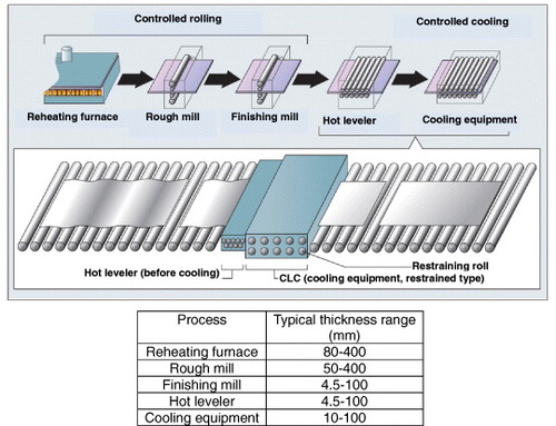
The present approach of using water-cooled TMCP, which gives accelerated cooling after low-temperature rolling and direct quenching, has been greatly improved in the 1980s. The continuous online control (CLC™) process, which is typically employed in TMCP facilities at Nippon Steel Corporation, for example, can cover a wide range of cooling parameters (i.e. heat transfer coefficient) and austenite conditions (i.e. unworked, recrystallized or non-recrystallized) and yields a variety of steel properties [Citation1, Citation22]. Several concepts are employed in the cooling equipment. In one of the most sophisticated present configurations, the plate is flattened by a leveler before water cooling (figure ) [Citation23]. This procedure is effective across a wide range of cooling rates for achieving uniform cooling throughout the plate plane and for realizing homogeneous mechanical properties. Further research and development has been carried out since some of the prototype TMCP facilities have become commercially available. Two very recent TMCP techniques CLC-μTM and Super-OLAC are overviewed later in this paper.
Figure 2 Schematic of TMCP facility in plate production line [Citation23].
Metallurgical aspects of TMCP
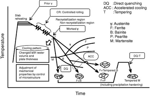
The concept of microstructural control by TMCP is schematically presented in figure [Citation7]. Whereas controlled rolling technology enhances toughness mainly by refinement of the ferrite microstructure, TMCP achieves high strength by utilizing the transformation to ferrite and bainite in addition to enhanced toughness. Accelerated cooling affords improved productivity compared with intercritical (austenite+ferrite region) rolling and minimizes any decrease in absorbed energy through the separation phenomena. TMCP consists of two stages in series: controlled rolling and a subsequent accelerated cooling process. During the rolling stage, the austenite grains are elongated into a pancake shape, which introduces crystallographic discontinuities such as ledges and deformation bands. These ledges and deformation bands remain until accelerated cooling starts when the rolling temperature is sufficiently low (below about 800 °C). Recrystallization occurs when the temperature is sufficiently high (above about 900 °C) and most of the ledges and deformation bands induced by deformation disappear. The retaining deformation ledges and bands can act as potential heterogeneous nucleation sites for the austenite to ferrite transformations and contribute to grain refinement. It is also worth noting that the heterogeneous deformation of austenite increases the grain surface area and the length of grain edges per unit volume, while there is no change in the number of grain corners per unit volume [Citation24].
Figure 3 Concept of microstructure control by TMCP [Citation7].
The other feature of TMCP is its cooling process. During the accelerated cooling the growth of transformed products is effectively suppressed and grain refinement is achieved by transformations where the aforementioned nucleation sites are introduced. The decrease in the transformation temperature caused by accelerated cooling induces strong changes in the intragranular structure. The transformation driving forces also contribute to grain size refinement through low-temperature rolling followed by water quenching. The tensile strength can be widely controlled (from 500 to over 800 MPa). It is also important to note that steelmaking and slab-reheating processes have to be carefully controlled to achieve steels with high strength and toughness.
The microalloying elements control the microstructure [Citation2]. Trace amounts of elements such as niobium and titanium in concentrations on the order of 0.01 mass% allow the microstructure to be refined from the slab-reheating to controlled-rolling and accelerated-cooling processes and enhance the strength of the final products. The effects of niobium, as an example of a microalloying element, are schematically illustrated in figure [Citation2, Citation14]. The size of the niobium precipitates formed during each process is roughly 300 nm at the slab reheating temperature before rolling (1000 °C or higher), 50 nm during controlled rolling (about 800 °C) and 10 nm at the transformation temperature (about 600 °C) during cooling. In summary, the size of newly formed precipitates decreases with decreasing in temperature as the process progresses. This is useful for microstructural control because the precipitates formed in the earlier processes are too large and thus useless for the subsequent processes. It is therefore necessary to maintain niobium in a solid solution so that it can be precipitated in sufficient amounts in the subsequent processes. The general solubility product can be expressed by the following equation, proposed by Irvine et al [Citation25]
(3) where the concentrations are expressed as weight percents and T is the absolute temperature.
Figure 4 Niobium precipitations at each stage of TMCP and their effects on the refinement of ferrite grains and precipitation hardening [Citation2, Citation13].
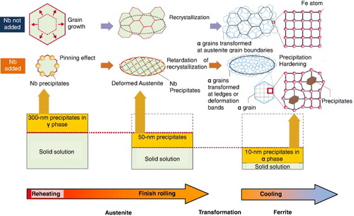
Niobium precipitates during slab reheating and prevents austenite grain growth via the pinning effect. During the subsequent rolling process, at below the recrystallization temperature (about 900 °C), the driving force generated by the strain energy introduced by such rolling facilitates the precipitation of fine niobium carbides and/or nitrides. These fine precipitates prevent austenite grain recrystallization and therefore coarsening. The effect of niobium on the recrystallization grain growth ratio G (μm s−1) can be expressed as [Citation26]
(4) Here A, B, C, D and E are constants, Fv is the strain energy of the crystals (J), DI is the austenite grain size diameter before deformation (μm), and Nbsol and Nbpre are the solute and precipitated niobium concentrations (mass%), respectively.
During thermomechanical rolling, the strain-induced precipitation of microalloying elements such as niobium plays an important role in controlling the microstructure [Citation27]. The reviews of Morrison [Citation28] and DeArdo [Citation29] mention that niobium delays the onset of austenite recrystallization. As tabulated by DeArdo et al (table ) [Citation29, Citation30], there is a lattice mismatch for niobium and vanadium precipitates in austenite, and thus the precipitates are located at crystalline defects in austenite (and also in ferrite). However Maruyama and Smith showed, using a three-dimensional atom probe, that the onset of recrystallization can be retarded by solute interstitial atoms and small substitutional–interstitial atomic clusters rather than by fine niobium carbonitrides [Citation31]. Because of the non-recrystallized nature of austenite, there is a plentiful supply of heterogeneous ferrite nucleation sites (ledges and deformation bands) for the subsequent cooling process. Recent in situ observations by neutron diffraction have also demonstrated that niobium addition and austenite deformation increase the ferrite transformation temperature [Citation32]. Niobium also induces other effects: during the austenite to ferrite transformation upon cooling, it precipitates in the ferrite matrix and enhances its strength via the precipitation strengthening mechanism. As reviewed by DeArdo et al [Citation30], precipitates such as NbCN, VCN, TiC and TiN exhibit a NaCl crystal structure and do not fit well in the ferrite lattice (table ) [Citation29, Citation30]. This incoherency between the ferrite and precipitates results in increased strength.
Table 1 Lattice mismatch (%) for niobium and vanadium precipitates in austenite and ferrite [Citation29, Citation30].
The TMCP parameters affect the microstructure and properties of niobium-titanium microalloyed steel. For example, the yield and tensile strength increase with a decrease in the finishing-cooling or non-recrystallization rolling temperature [Citation33].
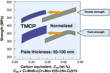
The most notable effect of TMCP is that steel with the same strength as conventional steels can be manufactured with a lower carbon equivalent (i.e. with lower alloy addition) through microstructural control. Figure shows the relationship between the carbon equivalent (Ceq) and the strength represented by the yield point (YP), and the tensile strength (TS) for TMCP and conventional TS 490 MPa normalized steels [Citation34]. It has been demonstrated that the value of Ceq required for TMCP steel to attain the same strength is 0.04–0.08 mass% lower than that required for normalized steel. The Ceq required to produce TS 490 MPa steel via the normalizing process is 0.39–0.44 mass%, while it is 0.33–0.36 mass% for TMCP. As a result, weldability (i.e. the preheating temperature required to prevent cold cracking at HAZ) has been significantly improved in TMCP steels. TMCP thus increases productivity in the fabrication of steel structures while enhancing safety and reliability.
Figure 5 Relationship between carbon equivalent and strength for TMCP and normalized steels [Citation34].
Equipment and production technologies for TMCP
In the establishment of TMCP, various types of accelerated cooling equipment have been proposed and put to practical use since 1980 in Japan and many other countries. The essential points in this development have been the uniformity and controllability of the cooling temperature and the plate flatness after cooling, as well as the productivity of the process. Commonly used accelerated cooling equipment has been thoroughly reviewed by Kinoshita et al [Citation35]. Each steel manufacturer adds specific features related to the cooling method, installation location and the motion of the plate. Currently, accelerated cooling equipment [Citation36] is mostly of the continuous type, in which the cooling zone is divided in the traveling direction of the plates. In this setup, water cooling of the top and bottom faces of the plate can be independently controlled in each zone.
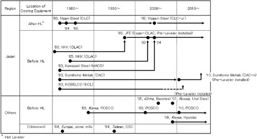
In addition to homogeneous water cooling, progress has been made in reduced-distortion cooling technology, which requires even more sophisticated cooling control [Citation35, Citation37]. This is needed to ensure both the uniformity of the cooling temperature and the required plate flatness after cooling. The issues related to plate distortion have already been thoroughly reviewed [Citation22, Citation35, Citation37, Citation38]. Some distortion modes for plates are schematically described in figure [Citation35, Citation37]. Wang et al classified the distortions (deflections) into three major types depending on the direction in which uneven cooling occurred, i.e., along the thickness, longitudinal and transverse directions [Citation38]. On the basis of thermal stress and elastic instability theory, they obtained expressions for the critical buckling along these three directions resulting from uneven cooling. One of the causes of plate distortion is the inevitable overcooling on the four narrow faces of the plate. To avoid this temperature decrease, several mechanistic measures can be taken: a water crown profile can be applied in the transverse direction (figure ) [Citation21], edge screening, which reduces the water flow along the plate edges, can be applied in the width direction (figure [Citation35, Citation37]), and head and tail screening can be applied to prevent overcooling at the respective narrow faces of the plate (figure [Citation35, Citation37]). To minimize the temperature difference, optimization of the nozzle arrangement at the bottom face has also been studied, since another mechanism that causes distortion is the different thermal histories of the top and bottom faces of the plate. At some steel manufacturers, learning functions are employed so that the ratio of water volume applied to the top and bottom faces can be automatically controlled on the basis of the accumulated data on temperature and flatness. The history of cooling equipment is briefly summarized in figure [Citation35, Citation37]. The flatness of the plate before cooling is essential for ensuring a uniform cooling temperature. This is consistent with the recent trend of optimizing the sequential equipment configuration by installing a hot leveler before the accelerated cooling stage.
Figure 6 Distortion modes due to non-uniformity of cooling over a plate [Citation35, Citation37].
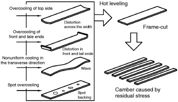
Figure 7 Cooling control system with water crown profile in transverse direction used to maintain plate flatness [Citation21].
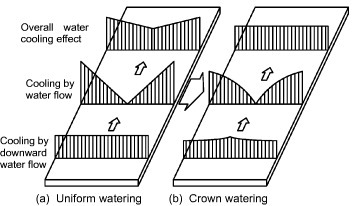
Figure 8 Cooling control system using width edge screening to maintain plate flatness [Citation35, Citation37].
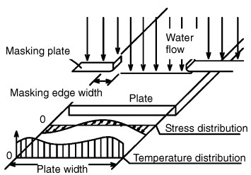
Figure 9 Cooling control system using head and tail edge screening to maintain plate flatness [Citation35, Citation37].
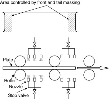
Figure 10 History of development of accelerated cooling equipment (from [Citation35, Citation37]).
Additional technologies have been required to meet the increasing demand for TMCP plates since the 1990s [Citation39]. A key issue in such technologies has been to achieve highly uniform cooling to minimize plate strain, which occasionally occurred with conventional TMCP methods and had to be rectified to reduce the amount of releveling. Product quality requirements have also become more severe and plates were needed to have less variation in their strength. This can be achieved through improved accuracy of the cooling finishing temperature during accelerated cooling. To respond to these requirements, some novel TMCP technologies, such as CLC-μ and Super OLAC [Citation39], have been developed and are now in used in production.
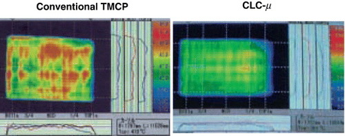
One of the improved cooling equipment systems, CLC-μ, was developed and introduced for commercial use by Nippon Steel Corporation [Citation23]. This system was a technical breakthrough for TMCP. Owing to its unique cooling technology, as well as the facility layout, a wide range of cooling rates and patterns and uniform cooling characteristics were realized over the entire plate. Nippon Steel Corporation conducted experiments and numerical analyses on thermal conductivity engineering and fluid dynamics and overcame the heterogeneity of the cooling behavior, which was not unavoidable using conventional cooling equipment [Citation40]. They developed a new water-cooling system with a wide range of cooling abilities, which reduced the temperature variation to approximately half that of conventional equipment as shown in figure [Citation23]. This new generation of controlled cooling technology is now widely applied to actual products, enabling the resolution of conflicting property requirements such as strength and toughness. Some examples are briefly introduced below.
Figure 11 Temperature distributions in plate surfaces after conventional TMCP and CLC-μ [Citation23]. (Reproduced with permission from [Citation23] ©2012 Nippon Steel Corporation.)
Omata et al reported another new cooling system [Citation39]. Heat transfer and boiling in the water cooling of steel plates are classified into two main mechanisms, nucleate boiling and film boiling, as shown in figure [Citation39]. Nucleate boiling occurs when the cooling water comes in direct contact with the plate surface and heat is transferred with the generation of steam bubbles. In film boiling, a film of steam is formed between the plate surface and the cooling water, and heat is transferred through the film. The cooling capacity in the case of nucleate boiling is known to be higher than that when a film is formed. When the cooling process starts in the accelerated cooling of steel plates, the plate surface temperature is very high, and thus cooling proceeds under the film-boiling condition. As the surface cools, the steam film becomes unstable and local contact occurs between the cooling water and plate. The boiling mechanism then shifts gradually to the nucleate type, passing through a transition boiling type mechanism, where nucleate boiling and film boiling coexist. The cooling behavior is intrinsically unstable in this transition zone because the cooling capacity increases as cooling proceeds. In conventional accelerated cooling, the top-face cooling water remains on the plate until evaporation is complete and induces secondary cooling over a large area. This secondary cooling drives the cooling mode into the unstable transition boiling condition, which increases the local temperature deviation after accelerated cooling.
Figure 12 Schematic boiling curves of Super-OLAC and conventional cooling systems [Citation39].
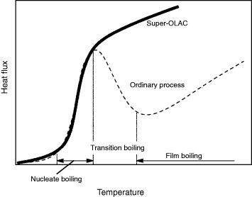
To rectify this problem caused by water remaining on the plates, a new cooling method, Super-OLAC [Citation39], was developed to realize nucleate boiling over the entire plate surface almost as soon as cooling starts, thus avoiding the transition boiling phase. This new method includes top-face cooling using a unidirectional ‘corridor’ flow of cooling water in the direction of plate transportation, from nozzles located close to the plate. It also employs bottom-side cooling by water sprayed from a high-density arrangement of nozzles in the water tank so that cooling is performed by the accompanying flow of water traveling with the plate.
The above-described measures have improved the uniformity of cooling temperature and plate flatness after cooling compared with past TMCP applications. However, the increasingly strict requirements for steel flatness necessitate further modifications of the accelerated cooling equipment and control measures to ensure plate flatness after cooling. To achieve this, some steel manufacturers have recently taken measures such as installing heavy cold levelers [Citation41].
Advances in peripheral technologies supporting TMCP
Technologies used in upstream processes to form very clean steel
In addition to TMCP, the slab purity is an important factor in the production of very tough steels. It is well known that trace impurities in steel have a profoundly adverse effect on steel toughness [Citation42]. For the stable production of very strong and tough steels, therefore, a reduction in the content of impurity elements such as phosphorus and sulfur is required. In recent years, mass-production high-purity steelmaking technologies have been developed to meet the demand for increased purity. Hot metal dephosphorization processes [Citation43], which can treat large quantities of steel, have reduced the phosphorus content to less than 0.010% through their optimum use with basic oxygen furnace (BOF) refining. Furthermore, progress has been made in vacuum treatment, such as the RH (Rheinstahl Hüttenwerke und Heraus) vacuum degassing process and ladle treatment. As a result, the phosphorus, sulfur and hydrogen concentrations in steel can be reduced to as low as [P]≤50 ppm, [S]≤10 ppm and [H]≤2 ppm [Citation44]. Such purity is important in liquefied natural gas (LNG) tanks, for which extremely high toughness at low temperatures is required, and for offshore structure components, which should have high lamellar-tear resistance.
In continuous casting technology, various measures have been taken to reduce center segregation, such as the use of electromagnetism, short-pitch divided rolls and soft-reduction casting methods. As a result, the purity of slabs has been improved [Citation43, Citation45]. The processes described above for making pure steel are indispensable for the production of high-strength, tough steels in conjunction with TMCP.
An example of an advanced steelmaking plant is located in the Kimitsu Works of Nippon Steel Corporation. It is equipped with three converters, two RH degassers and two continuous slab casters, and produces slabs for various products, such as heavy plates and pipes. Its continuous caster, which was installed in 2006 to improve the slab quality, can manufacture a heavy slab with a thickness of up to 300 mm [Citation46]. Sumitomo Metal Industries have developed a process for controlling the porosity of casting slabs to improve the center porosity grade, which was tested on a 300 mm-thick slab by applying reduction under the condition of nearly complete solidification [Citation47]. The forging of continuously cast slabs has also been reported to be effective. Araki et al. [Citation48] improved the slab properties by applying a forging process to a 310-mm-thick slab with a reduction ratio (original slab thickness/plate thickness) of 1.3.
Computational material designing technology for TMCP
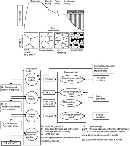
TMCP steel is produced by precisely controlling the conditions of reheating, rolling and cooling. However, the resulting properties however fluctuate owing to slight deviations in the process conditions. A material design model has been developed to quantitatively predict the properties of products from the final microstructure by theoretically predicting the microstructural changes due to deviations under the processing conditions. The general configuration of the model in practical use is shown in figure [Citation49, Citation50]. This integrated model is designed to predict the properties (e.g. strength, toughness) of different microstructures by using process and metallurgical models to predict changes in the microstructure during the reheating, hot working and cooling processes. The metallurgical model consists of an initial status model, hot working model, transformation model, and microstructure and properties model. The hot working model calculates the changes in the austenite microstructure (i.e. deformation of the microstructure, recrystallization and subsequent grain growth) during one-pass rolling, starting from a certain initial size of the austenite grains. The models repeat such calculations for each pass in multipass rolling. To establish this computational material design technology, the validity of the models was verified using extensive data [Citation50] collected by in-line thermal samplers developed for this purpose.
Figure 13 Schematic of thermal cycle in TMCP and changes in microstructure (top) and the computational model (bottom) [Citation49, Citation50].
Compared with the conventional method of designing plates by starting from the chemical composition and process parameter properties and using regression analysis, the computational material design by modeling has the following advantages:
The microstructure can be predicted at every stage.
Control factors in the manufacturing are incorporated.
The modeling method can be applied to a variety of tasks such as (i) minimization of the fluctuations in properties, (ii) rapid assessment of the production capability for new commercial orders, (iii) the integration of steel grades and (iv) the rapid and economical development of new products.
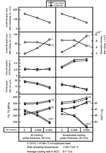
The calculated and experimental tensile properties and toughness are in very good agreement as shown in figure [Citation51]. This figure also demonstrates the quantitative effects of niobium on these properties, as described above.
Figure 14 Microstructural characteristics and mechanical properties of steel manufactured with a steel mill (comparison between measured and calculated values) [Citation51].
Chen and Linkens reported another numerical approach for the predictions of properties. They demonstrated that neuro-fuzzy models can predict Charpy impact properties for given steel compositions and processing parameters [Citation52]. These techniques can be used for designing alloys and process conditions.
High HAZ toughness technologies
To reduce the fabrication cost of steel structures, high or ultrahigh heat input (about 300 to 1300 kJ cm−1) in highly efficient welding technologies has recently been widely applied, especially in Japanese industry [Citation12, Citation53]. Although, as reviewed below, many new types of steel plates with high performance of the base metal have recently been developed, there is a need for plates that can also maintain HAZ toughness even after such ultrahigh-heat-input welding. Refinement of the grain size, at which cleavage fracture occurs, is an effective means of improving HAZ toughness for steels after conventional to ultrahigh heat input. There are two major technologies used for grain size refinement [Citation8–10, Citation12]: refinement of the austenite grain size before the austenite to ferrite transformation (figure (a)), and the application of an intragranular ferrite transformation (figure (b)). The latter is initiated with the use of TiN to provide nucleation sites [Citation54]. A variety of such inclusions (e.g. titanium oxide) can act as ferrite nucleation sites in the HAZ [Citation12]. Refinement of the austenite grain size has always been very difficult owing to its thermal history during ultrahigh-heat-input welding. It has been particularly difficult to prevent austenite grain growth during the slow cooling from elevated temperatures in the bond regions. Austenite grain growth can be retarded by pinning particles, as expressed by the well-established Zener equation [Citation55–57],
(5) Here R is the radius of an austenite crystal grain, r is the radius of a second-phase particle and f is the volume fraction of second-phase particles.
Figure 15 Schematic of HAZ microstructure control [Citation8–10, Citation12]. WM: weld metal, GBF: grain boundary ferrite (allotriomorph), FL: fusion line, FSP: ferrite side plate, γ: austenite, IGF: intragranular ferrite and Bu: upper bainite.
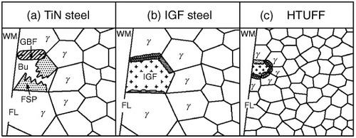
Pinning by TiN particles is a well-established technology, but unfortunately it is not as effective in the case of high-heat-input welding. The number of TiN particles decreases during welding because TiN is thermally unstable to prolonged heating at or above 1200 °C and/or because Ostwald ripening occurs. To overcome these problems in TiN steels, superhigh-toughness technology (HTUFFTM) has been developed, which involves the addition of fine particles to obtain a fine microstructure [Citation8–12]. Although HTUFF is a holistic term covering various types of high HAZ toughness technologies, one that involves austenite grain size refinement by particles is described below.
As reviewed by Uemori [Citation12], many studies have focused on the application of more thermally stable oxides and sulfides rather than nitrides to retard HAZ austenite grain growth. Examples include REM(O,S) (i.e. oxysulfide of rare-earth metal) and Ca(O,S) (i.e. oxysulfide of calcium). These particles exhibit a pinning effect against austenite grain growth, as schematically illustrated in figure (c), and act as nucleation sites for the intragranular ferrite transformation. Whether these potential microstructure-controlling ‘seeds’ can be used for ultrahigh-heat-input welding was not examined until recently. A recent study revealed that ultrafine particles (several ten to several hundred nm; oxides or sulfides containing magnesium or calcium), if introduced with sufficiently high density in steel, can realize very fine austenite grains. Some examples of such ultrafine particles are shown in figure [Citation9, Citation10, Citation12]. These particles can even be observed in samples that were water-quenched from 1400 °C, proving that these particles exist even at 1400 °C rather than as a solution of each element. As shown in figure [Citation8–10, Citation12], the austenite grain size was limited to about 70 μm by the imparted pinning particles followed by heating for 1–100 s heating at 1400 °C. This strong pinning effect has never been observed in conventional steels. Commercial HTUFF steel plates are now widely used in building construction, shipbuilding, offshore structures and line pipes. It is surprising that the very small inclusions of about 50–200 nm in diameter can control the overall mechanical properties of steel structures. An example of the application of HTUFF technology is described below.
Figure 16 Examples of pinning particles in HTUFF steels [Citation9, Citation10, Citation12]. (Reproduced with permission from [Citation10] ©2012 Nippon Steel Corporation.)
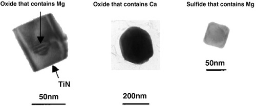
Figure 17 Comparison of austenite grain growth between HTUFF and TiN steels in simulated HAZ of weld fusion line [Citation8–10, Citation12].
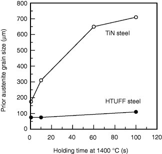
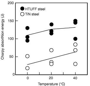
Figure [Citation10, Citation12] shows HAZ microstructures of conventional and HTUFF steels with a tensile strength of 590 MPa, which are used in building construction. These microstructures are typical for model weld joints, which can be used to simulate the actual box-column diaphragm joints routinely produced in welding fabricators. The austenite grain size in the developed HTUFF HAZ microstructure (top) is clearly finer than that in conventional steel (bottom). The simulated toughness of these HTUFF HAZ steels is much higher than that of conventional steels as shown in figure [Citation11]. Note that the Charpy absorption energy of HTUFF steel exceeds 70 J. Such values were required for building construction following the analysis of the effect of the catastrophic Hanshin-Awaji Earthquake (1995) in Japan [Citation11].
Figure 18 Comparison of HAZ microstructures between developed HTUFF and conventional steels after electro-slag welding [Citation10, Citation12]. (Reproduced with permission from [Citation10] ©2012 Nippon Steel Corporation.)
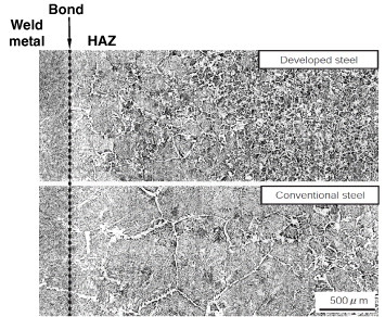
Figure 19 Simulated HAZ of BT-HT355C class steels [Citation11]. The heat input equivalent is electro-slag welding at 700 kJ cm−1 of electro-slag welding and reheat peak temperature is 1400 °C.
In addition to the HTUFF technology, the optimized use of boron was recently reported to improve HAZ toughness [Citation58]. Two mechanisms are responsible for the enhanced toughness due to the addition of boron:
Solute boron refines the ferrite allotriomorph thickness of grain boundaries.
BN precipitates subdivide ferrite grains at austenite boundaries, providing heterogeneous nucleation sites.
Applications of TMCP steels
Introduction and background
The relationship between market requirements and the role of TMCP is summarized in figure [Citation7]. Since the first application of TMCP in the shipbuilding industry, TMCP steel has found uses in many plate markets (table [Citation7]). The popularity of TMCP reflects the advantages of TMCP steel such as enhanced strength and toughness coupled with excellent weldability. Another key issue that might explain the success of TMCP is that alloy design, impurity control during the steelmaking process, segregation reduction, hydrogen removal, slab reheating, and the rolling and cooling processes are considered in both the upstream and downstream processes.
Figure 20 Relationship between market requirements and roles of TMCP [Citation7].
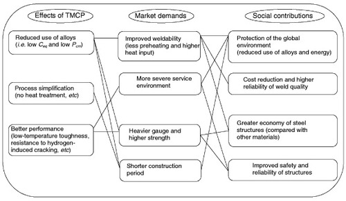
Table 2 Tensile strength class and applications of steel plates manufactured by TMCP (modified after [Citation7]).
Some examples of successful applications of TMCP steels in various industries are introduced below.
Shipbuilding
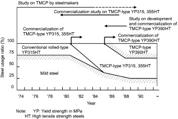
The first application of TMCP steel was in the shipbuilding industry. Moreover, the development of TMCP steel has promoted the use of high tensile-strength (HT) steels. Figure shows the trend in the use of different types of steel in large tankers [Citation59]. Owing to the development of TMCP steel, the fraction of HT steels increased from 20–30% to 60–70% in the 1980s. HT steels with a yield point of up to 390 MPa have also been used in large tankers. The application of HT steels (including high-yield-point steels) has made it possible to significantly reduce ship weight and cost and save energy. To improve transport efficiency, modern container ships are markedly larger than in the past and can accommodate more than 6000 containers. YP 390-class heavy plate with a thickness of above 60 mm has been used for important parts of large hulls such as sheer strakes and hatch coamings. A welding procedure with an ultrahigh heat input of 35–45 kJ mm−1 (single pass electro-gas welding (EGW)) has been employed in the manufacture of these vessels. The plates used for these important parts have been manufactured by combining TMCP with technology to prevent the coarsening of the microstructure in the HAZ.
Figure 21 Evolution of the use of different types of steel in large tankers [Citation59].
The recent increase in maritime transport has led to the construction of larger container ships for more efficient transportation. This, however, has introduced new problems: the need for a heavier hull, i.e. thicker steel plates, and complex welding. To solve these problems, Nippon Steel Corporation has developed YP460-class steel plates, which are stronger than conventional YP390 steel plates, and used them in the construction of actual ships [Citation60]. Examples of the mechanical properties of YP460-class steel are given in table [Citation61].
Table 3 Specifications and mechanical properties of YP460 (Grade-E) steel [Citation61].
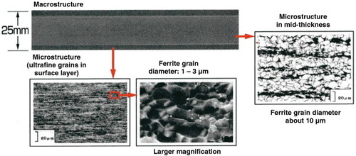
Accidents caused by the collision or grounding of ships, such as large-scale crude oil spills, still occur around the world. Under such circumstances, there is growing demand for safer and more reliable ships to prevent hull failures and the concomitant environmental damage. For this purpose, highly crack-resistant steel plates with an ultrafine-grain surface layer (HIARESTTM) have been developed. The crack arrestability of these plates is significantly improved by the ultrafine microstructure in the surface layer as shown in figure [Citation2, Citation62]. These plates exhibit high crack arrestability of over 6000 MPa m0.5 at a temperature of −10 °C even when subjected to a plastic strain of 10% to simulate damage due to collision or grounding [Citation63]. These plates have already been incorporated in the sheer strakes of liquefied petroleum gas (LPG) tankers and bulk carriers. The production method for these plates differs from conventional TMCP in that accelerated cooling is performed during rolling. This advanced TMCP process will broaden the applicability of TMCP.
Figure 22 Macrostructure and microstructures of SUF steel plate (HIAREST) [Citation2, Citation62]. (Reproduced with permission from [Citation2] ©2012 Nippon Steel Corporation.)
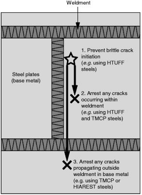
To ensure the safety of welded steel structures, both the plate metal and the weldment have to be considered. The following fail-safe procedures must be implemented (figure ) [Citation2, Citation14]: (i) brittle crack initiation must be avoided, (ii) if a brittle crack occurs, it must be arrested in the weldment and (iii) any crack that propagates beyond the weldment must be arrested within the base metal. The safety of structures can be enhanced by employing TMCP (including HIAREST, as described above) to improve the base metal toughness, and by the impartation of titanium oxide and the implementation of HTUFF to improve HAZ toughness. Shirahata et al provide examples of the application of 70-mm-thick YP460 steel in shipbuilding by considering the results of Charpy and deep-notch tests on electro-gas weld joints [Citation58].
Figure 23 Schematic of safeguards to prevent brittle failure in welded structures [Citation2,Citation14].
Offshore structures
In recent years, the exploitation of offshore oil and gas resources has moved into deeper waters and colder regions, such as the northern part of the North Sea and the Arctic Ocean. Offshore structures have increased in size to meet recent requirements of the energy industry. As these structures are exposed to extremely low temperatures, the steels used need to be thicker and tougher. The yield strength required for most uses has increased from 355 to 500 MPa [Citation64]. Other requirements include a lower preheating temperature of the steel and cost reduction by optimizing the construction and welding processes. In this application, toughness based on fracture mechanics has been adopted in addition to that represented by the Charpy impact value to improve safety. There is a growing need for steels for which a high critical crack tip opening displacement (CTOD) value at low temperatures (e.g. 0.25 mm at −10 °C) is required in the HAZ. In short, high-strength heavy plates, which can be welded with a high heat input and have sufficiently high fracture toughness at low temperatures, are now required for offshore structures. Toughness after high-heat-input welding has a trade-off relationship with strength, however, and the conventional method of quality design based on alloying has certain limitations. In contrast, TMCP and other related metallurgical technologies can solve for these problems.
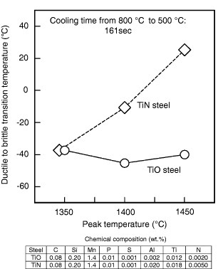
The maximum temperature in the HAZ exceeds 1400 °C owing to the high-heat-input welding, meaning that fine precipitates, such as TiN, may dissolve. A technology to achieve high HAZ toughness has been developed by utilizing intragranular ferrite, which is formed on fine oxides. The plates of offshore structures developed use titanium oxide, which is stable even at high temperatures [Citation65]. Figure [Citation66] shows the simulated HAZ toughness, represented by the ductile to brittle transition temperature, of TiO steel in comparison with that of a TiN steel, which does not contain titanium oxide. The toughness of the former is excellent, because titanium oxide particles are stable even in the high-temperature region close to the weld metal and function as effective nucleation sites for the intragranular ferrite transformation. Owing to the combination of TMCP with titanium oxide, 355–500-MPa-class CTOD-guaranteed plates for offshore structures have been developed and applied in many projects.
Figure 24 Change in Charpy-V-notch transition temperature of simulated HAZ with peak temperature [Citation66].
Building construction
The application of TMCP steel as a high-strength material in building construction has gradually increased since the early 1990s. At present, TMCP plates account for more than 10% of the plate steel used in building construction. Table provides some examples of the use of TMCP steel in building construction projects in Japan [Citation7]. This steel has been widely accepted in Japan because it readily meets the requirements for high-rise buildings and large-span structures owing to its higher welding efficiency. Since Japan is subject to frequent earthquakes, high-strength and low-yield-ratio (YR) steels [Citation67], which absorb seismic energy through plastic deformation, have been widely applied to high-rise buildings. To ensure a low yield ratio, careful control of the volume fraction and grain size of soft ferrite is necessary. The production of high-strength, low-YR steel has been realized by applying TMCP technology with accelerated cooling at a moderate rate, while keeping the cooling start temperature below the equilibrium transformation temperature from austenite to ferrite during cooling, Ar3. High-strength steels for building construction used to be manufactured by heat-treatment processes such as the quench-lamellarize-temper (QLT) process [Citation22, Citation68]. CLC-μ has reduced the number of heat-treatment processes and the amount of alloying elements, thus reducing the material cost.
Table 4 Examples of application of TMCP steel for building constructions in Japan (modified after [Citation7]).
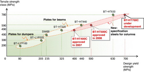
New steels (BT-HT400C and BT-HT500C, figure ) have also been developed for building construction by CLC-μ, which enhances the yield strength by 23–54% [Citation14]. The excellent toughness and weldability of these steels were retained by refining the grain size. An example of the application of these steels can be seen in the Tokyo Sky Tree tower. This tower is being built in Sumida-ward, Tokyo, with completion due in 2012, and at a height of 634 m, it will be one of the world's tallest structures.
Figure 25 Specifications of steels used in building structures in Japan [Citation14].
Bridges
Table shows some examples of the use of TMCP steel for bridge projects in Japan [Citation7]. In the bridge market, recent trends include the reduction in the number of main girders and the improvement of welding efficiency by using thicker, high-strength plates in rationalized bridge designs. The use of TMCP steel in bridge construction has been increasing as it can meet the above requirements. For long-span bridges, a copper-precipitation-hardening HT 780 MPa TMCP steel with low-temperature characteristics has been developed [Citation69]. This steel was first used in the Akashi Strait Bridge, one of the world's longest suspension bridges, and contributed greatly to the improved performance of the bridge and to reducing the construction cost.
Table 5 Examples of application of TMCP steel for bridges in Japan (modified after [Citation7]).
High yield strength steel plates for bridges (SBHS) were specified in the Japanese Industrial Standards as JIS G 3140 in 2008 (table ). In the production of SBHS steels, Nippon Steel Corporation applied CLC-μ technology, which simultaneously affords excellent properties such as high tensile strength, high fracture toughness, good weldability and ease of fabrication. Examples of these properties are shown in figure [Citation70]. SBHS was adopted for the Tokyo Gate Bridge (on the 4.6 km section from the reclaimed land outside the central breakwater to Wakasu, Koto-ward), which was completed in 2011. CLC-μ technology has also been adapted for steels used in building constructions.
Figure 26 Examples of chemical composition and mechanical properties of SBHS500 [Citation70]: (a) tensile test results and (b) Charpy impact test results. (Reproduced with permission from [Citation70] ©2012 Nippon Steel Corporation.)
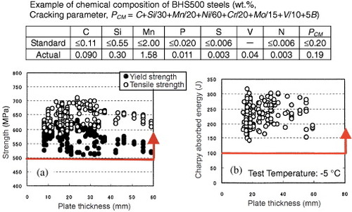
Table 6 Specifications of SBHS (high-yield-strength steel plates for bridges, Japanese Industrial Standard JIS G 3140).
Pipelines
TMCP steel is also used for line pipes, including pipes for sour gas services, owing to its high strength and excellent low-temperature toughness [Citation71, Citation72]. Table shows examples of the use of TMCP steel in recent line-pipe projects [Citation7]. To prevent hydrogen-induced cracking in acidic environments, the hardened microstructure area, which is sensitive to hydrogen-induced cracking, must be reduced. Reduction of the sulfur content and the morphological control of sulfides by adding calcium are also effective. TMCP can reduce the amount of hard structures and markedly improve the resistance to hydrogen-induced cracking (figure [Citation73]). The formation of hard structures can be explained by the diffusion of carbon, which results from the γ to α transformation. In the case of conventional air-cooling, carbon readily diffuses, from the non-segregation zone with a higher transformation temperature (Ar3) to the central segregation zone with a lower Ar3 during the austenite to ferrite transformation, forming a hardened structure in the center zone. In accelerated cooling, carbon diffuses slowly as the cooling rate is very high, and consequently the formation of the hardened structure is suppressed. TMCP is thus beneficial for improving resistance to hydrogen-induced cracking. Consequently, TMCP steels have been used for many pipeline projects involving sour gas services. The application of TMCP with a large reduction per pass during hot rolling [Citation74] has made it possible to manufacture API (American Petroleum Institute) grade X120 [Citation75] line pipes with high strength, where the minimum yield strength in the circumferential direction is at least 120 ksi (827 MPa), and excellent low-temperature toughness. This new steel is expected to be used extensively in new projects.
Figure 27 Effect of the final temperature of accelerated cooling on the resistance to hydrogen-induced cracking and other mechanical properties [Citation73].
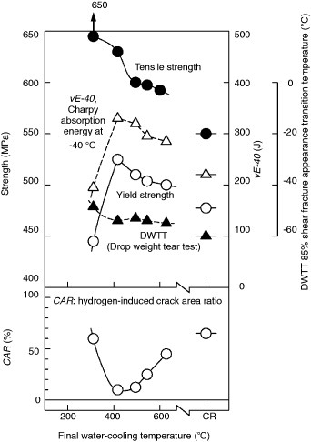
Table 7 Examples of application of TMCP steels for line pipe projects (modified after [Citation7]).
Penstocks
Penstocks (pipes for hydroelectric stations) require the highest strength and heaviest plates among the applications of steel. Hitherto, high-strength steels of up to HT 780 MPa have been used. In recent years, however, higher strength has been required to handle even greater water pressures (e.g. for 2700 MW class power generation) and reduce costs. To satisfy such requirements, ultraheavy 100-mm-thick HT 950 MPa steel (controlled rolling-direct quench and temper: CR-DQT) has been developed by applying TMCP [Citation76–78]. The key to the development of this steel is to ensure a uniform through-thickness distribution of strength and toughness. Using ultraheavy HT 950 MPa steel, conventional quenching and tempering result in insufficient quenching in the interior of the steel compared with its surface because of the difference in cooling rates between the surface and interior. It is therefore difficult to obtain a uniform distribution of strength and toughness throughout the thickness. However, TMCP (CR-DQT) enables high strength and toughness to be realized throughout the thickness through control of the austenite grain size and the subsequent direct quenching. The austenite grains are fine at the surface and coarse in the bulk immediately after rolling. The larger austenite grains have higher hardenability and can compensate for the lower cooling rate inside the plate.
Cryogenic tanks
In cryogenic tanks, high crack arrestability is required for both the base plate and welded joints. To satisfy such requirements, 3.5 mass% nickel steel is used for LPG tanks operating at –50 °C. Low-cost plates with reduced nickel content (1.5 mass% nickel) and sufficiently high crack arrestability have been developed by applying TMCP and put to commercial use [Citation79]. Steel with even lower nickel content (0.5 mass% [Citation62]) and excellent crack arrestability has developed using TMCP with HTUFF, as described elsewhere in this review.
Future prospects for TMCP
As reviewed in this paper, advances in TMCP over the last thirty years have been particularly notable in Japan, and these advances are expected to be adopted worldwide. It is often said that the 21st century will focus on the protection of the global environment. In recent years, many discussions have been held worldwide about the lifecycle assessment of structures, global warming and the protection of the environment as urgent and important issues. From the view points of the global environment and society's need to better conserve resources and energy, it will become increasingly important to improve the safety and further extend the lifetime of structures. It is therefore expected that properties that will help satisfy these needs will be required of steels. TMCP is expected to strategies that will lead to resource conservation.
Future market requirements for TMCP steels are expected to be as follows:
Enhanced strength to enable to structural weight reduction.
Improved toughness and strength to ensure safety in earthquakes, fires and other disasters.
Greater reliability and resistance to fatigue and corrosion.
Advanced weldability in high-heat-input welding to reduce the cost of fabrication.
Better workability.
Conclusions
In this paper, TMCP technology and its applications have been reviewed. The range of applications of TMCP has steadily expanded by responding to market needs. It is expected that the market requirements for TMCP steel will become increasingly exacting and diverse in the future. TMCP has the potential to meet such requirements owing to ongoing developments. It would be a great honor for us if we could contribute in any way to creating advanced steels that will help Japan to recover from the recent catastrophe of the 2011 Tohoku earthquake and tsunami and better protect people's lives against future natural disasters. These are indeed our social responsibilities as material scientists and engineers.
Acknowledgments
The authors gratefully acknowledge Dr Teruo Kishi, Professor Emeritus of the University of Tokyo, and Mr Norio Katsuyama, Executive Vice President of Nippon Steel Corporation, for providing the opportunity to write this paper and advice. The authors also acknowledge the contributions of Mr Yuzuru Yoshida, Mr Yuji Honda, Dr Ryuji Uemori and Mr Masaaki Fujioka at Nippon Steel Corporation for their kind support.
References
- YoshieA 2005 Techno Marine No. 885 Tokyo The Society of Naval Architects of Japan 331
- Tetsu no Usuita-Astuita ga Wakaru Hon 2009 Tokyo: Nippon Steel Corporation (Nihon-Jitsugyo-Shuppan-Sha) (in Japanese)
- YoshieASasakiJ 2010 Niobium Bearing Structural Steels StevenG JJitendraPWarrendale, PA The Minerals, Metals and Materials Society p 291
- TanakaY 2005 Proc. PVP2005, 2005 ASME Pressure Vessels and Piping Division Conf. p 515 (Denver, Colorado, USA)
- YuriokaN 1992 J. Japan . Weld. Soc. 61 50
- KobayashiE 1985 TMCP no Yousetsu-Yakin, Symp., Yousetuyakin-Kenkyuu-Iinkai Dai-100-Kinen (The Japan Welding Society) (in Japanese) p 177
- NishiokaK 2000 Thermomechanical Proc. Steels (London, UK) p 3
- KojmaAUemoriRMinagawaMHoshinoMIchikawaK 2003 Mater. Japan 42 67 (in Japanese) http://dx.doi.org/10.2320/materia.42.67
- UemoriR 2004 Nishiyama-kinen-koza Tokyo The Iron and Steel Institute of Japan p 91 (in Japanese)
- KojimaAKiyoseAUemoriRMinagawaMHoshinoMNakashimaTIshidaKYasuiH 2004 Nippon Steel Technical. Report. No. 90 2
- KojimaAYoshiiKHadaTSaekiOIchikawaKYoshidaYShimuraYAzumaK 2004 Nippon Steel Technical Report. No. 90 39
- UemoriR 2009 Bull. Iron Steel Inst. Japan 14 34 (in Japanese)
- Research Institute of Innovative Technology for the Earth 11th January 2008 International Comparisons of Energy Efficiency (Sectors of Electricity Generation, Iron and Steel, Cement) p 4
- IchikawaKFujiokaMUemoriRYoshieA 2011 Int. Symp. Recent Developments in Plate Steels p 103 (Winter Park, Colorado, USA)
- KagiwadaNMiyanoK 1956 Tetsu-to-Hagané, J. Iron Steel Inst. Japan 42 830
- HallE O 1953 Proc. Phys. Soc. B 64 747 http://dx.doi.org/10.1088/0370-1301/64/9/303
- PetchN J 1953 J. Iron Steel Inst. 174 25
- PickeringF B 1978 Physical Metallurgy and the Design of Steels London Applied Science Publications Ltd p 63
- SekineHMaruyamaT 1976 Seitetsu Kenkyu No. 289 43 (in Japanese)
- TanakaT 1981 Int. Met. Rev. 4 185 http://dx.doi.org/10.1179/095066081790149258
- OnoeYUmenoMMantaniOSogoYSakaiKIwanagaKMorikawaH 1983 Nippon Steel Technical. Report No. 22 l
- OkamotoKYoshieANakaoH 1993 Proc. Int. Symp. Phys. Met. Direct-Quenched Steels TaylorK AThompsonS WFletcherF BWarrandale, PA The Minerals, Metals and Materials Society p 339
- UenoH 2006 Nippon Steel Mon. 163 12 (in Japanese)
- SinghS BBhadeshiaH K D H 1998 Mater. Sci. Technol. 14 832 http://dx.doi.org/10.1179/026708398790301043
- IrvineK JPickeringF BGladmanT 1967 J. Iron Steel Inst. 205 161
- YoshieAFujitaTFujiokaMOkamotoKMorikawaHMabuchiH 1994 Tetsu-to-Hagané, J. Iron Steel Inst. Japan. 80 50
- NagarajanVPalmiereE JSellarsC M 2009 Mater. Sci. Technol. 25 1168 http://dx.doi.org/10.1179/174328409X455242
- MorrisonW B 2009 Mater. Sci. Technol. 25 1066 http://dx.doi.org/10.1179/174328409X453299
- DeArdoA J 2003 Int. Mater. Rev. 48 371 http://dx.doi.org/10.1179/095066003225008833
- DeArdoA JHuaM JChoK GGarciaC I 2009 Mater. Sci. Technol. 25 1074 http://dx.doi.org/10.1179/174328409X455233
- MaruyamaNSmithG D W 2002 Mater. Sci. Eng. A 327 34 http://dx.doi.org/10.1016/S0921-5093(01)01889-5
- XuP GTomotaYLukášPMuránkskyOAdachiY 2006 Mater. Sci. Eng. A 435–436 46 http://dx.doi.org/10.1016/j.msea.2006.06.002
- LiuYZhuFLiYWangG 2005 ISIJ Int. 45 851 http://dx.doi.org/10.2355/isijinternational.45.851
- SuzukiHSogoYIwanagaKYamabaRMaedaKOhnoY 1984 IIW Doc. 1314
- KinoshitaHAndoRWadaTMurakamiH 2004 Bull. Iron Steel Inst. Japan . 9 636 (in Japanese)
- NakamuraHKatoMMiyawakiHHoshinaYYamamotoMUekajiH 1990 Nippon Steel Technical Report No. 44 l
- Handbook of Iron and Steel, 4th edition, CD-ROM 2002 (Tokyo: The Iron and Steel Institute of Japan) (in Japanese)
- WangS-CChiuF-JHoT-Y 1996 Mater. Sci. Technol. 12 64
- OmataKYoshimuraHYamamotoS 2003 NKK Tech. Rev. 88 73
- SerizawaYYamamotoR 2007 J. Japan Soc. Mech. Eng. 110 8 (in Japanese)
- MatsumotoTOheKUedaTWatanabeKNozakiFHamaguchiM 1999 Report of the ISIJ Meeting (CAMP-ISIJ) Vol. 12 Tokyo The Iron and Steel Institute of Japan p 1093 (in Japanese)
- FurukimiOSaitoY 1990 ISIJ Int. 30 390 http://dx.doi.org/10.2355/isijinternational.30.390
- SumidaMAndoMNakamuraHNakashimaHTakasakiY 1983 Tetsu-to-Hagané, J. Iron Steel Inst. Japan 69 S959 (in Japanese)
- OhsawaK 1995 Tetsu-to-Hagané, J. Iron Steel Inst. Japan. 81 449–454 (in Japanese)
- ChinoHAbeMKatayamaKTamehiroHAkasakiH 1990 Proc. Pipeline Technology. Conf. Ostend (ed.) Dennys 4.l
- NiizumaMFukudaJMatsumotoTKurokiMShimaSMarukiY 2008 6th Eur. Conf. Continuous Casting (Riccione, Italy)
- SatouYKumakuraSOtaKHirakiSShiraiYYamanakaA 2008 Rep. ISIJ Meeting (CAMP-ISIJ) 21 Tokyo The Iron and Steel Institute of Japan 104 (in Japanese)
- ArakiKKohriyamaTNakamuraM 1998 K awasaki Steel Giho 30 57 (in Japanese)
- YoshieAFujiokaMWatanabeYNishiokaKMorikawaH 1992 ISIJ Int. 32 395 http://dx.doi.org/10.2355/isijinternational.32.395
- WatanabeYShimomuraSFunatoKNishiokaKYoshieAFujiokaM 1992 ISIJ Int. 32 405 http://dx.doi.org/10.2355/isijinternational.32.405
- YoshieA 1994 Doctor Thesis Kyushu University, Japan (in Japanese)
- ChenM-YLinkensD A 2006 ISIJ Int. 46 586 http://dx.doi.org/10.2355/isijinternational.46.586
- IchikawaKHashibaYNogamiAFukudaY 2005 Mathematical Modelling of Weld Phenomena vol. 7 CerjakHH K D HBhadeshiaH K D HKozeschnikE Graz Austria Technische Universität Graz p 463
- KanazawaSNakashimaAOkamotoKKanayaK 1975 Tetsu-to-Hagané, J. Iron Steel Inst. Japan. 61 2589 (in Japanese)
- ZenerC 1948 Trans. Am. Inst. Mining Met. Eng. 175 15
- NishizawaTOhnumaIIshidaK 1997 Mater. Trans. JIM 38 950
- ManoharP AFerryMChandraT 1998 ISIJ Int. 38 913 http://dx.doi.org/10.2355/isijinternational.38.913
- ShirahataHOtaniJFunatsuYInoueT 2011 Proc. 21st) Int. Offshore Polar Eng. Conf. p 93 (Maui, Hawaii, USA)
- ImaiS 1996 Tekkou The Japan Iron and Steel Fed. No. 6 13 (in Japanese)
- FunatsuYOtaniJHirotaKMatsumotoTYajimaH 2011 Proc. 21st Int. Offshore Polar Eng. Conf. p 102 (Maui, Hawaii, USA)
- OtaniJFunatsuYInoueTShirahataH 2011 Proc. 21st Int. Offshore Polar Eng. Conf. p 98 (Maui, Hawaii, USA)
- IshikawaTMabuchiHHasegawaTNomiyamaYYoshieA 1999 Tetsu-to-Hagané, J. Iron Steel Inst. Japan. 85 544 (in Japanese)
- IshikawaTInoueTHagiharaYOoshitaSKurokiTHashimotoKTadaMYajimaH 1995 Bull. Soc. Naval Architects Japan. 752 16
- NagaiYFukamiHInoueHNakashimaTKojimaAKajitaniTAdachiTYoshidaY 2003 Proc. 22nd Int. Conf. Offshore Mechanics Arctic Eng. p 319
- OhkitaSWakabayashiMHommaHYamamotoKMatsudaS 1988 Nippon Steel Technical Report No. 37 10
- YamamotoKMatsudaSHazeTChijiiwaRMimuraH 1989 Residual and Unspecified Elements in Steel S MelilliE G Nisbett Philadelphia ASTM 266
- OhashiMMochizukiHYamaguchiTHagiwaraYKuwamuraHOkamuraYTomitaYKomatsuNFunatsuY 1990 Nippon Steel Technical Report No. 44 8
- OhashiMTsuruSNakaoH 1991 Rep. ISIJ Meeting (CAMP-ISIJ) Tokyo The Iron and Steel Institute of Japan 758
- OkamuraYTanakaMOkushimaMYamabaRTamehiroHInoueHKasuyaTSetoA 1995 Nippon Steel Technical Report No. 66 65
- HommaKTanakaMMatsuokaKKasuyaTKawasakiH 2008 Nippon Steel Technical Report No. 97 51
- NishiokaKTamehiroH 1988 Microalloyed HSLA Steels World Materials Congress p 597
- NakasugiHTamehiroHNishiokaKOgataYKawadaY 1990 Int. Conf. Welding-90 p 125
- TamehiroHTakedaTMatsudaSYamamotoKOkumuraN 1985 Trans. ISIJ 25 982 http://dx.doi.org/10.2355/isijinternational1966.25.982
- NishiokaKMizutaniYHoriYKojimaAOgawaS 1997 Nippon Steel Technical Report No. 75 9
- AsahiH et al 2004 Nippon Steel Technical Report No. 90 82
- YanoSOkamuraYInoueTTanabeKMaeharaSMuraokaHToyofukuAHoriiY 1989 Nippon Steel Technical Report No. 42 20
- MatsukawaYArimochiKOnishiK 1998 Sumitomo Metals 50 105 (in Japanese)
- SampeiTSakuiSHondaTIshikawaHNaganawaH 1990 NKK Gihou No. 133 37
- ChijiiwaRInoueTYoshidaYIsodaSDoiNTamehiroHYoshieAHattoriK 1997 Nippon Steel Technical Report No. 75 51
- HosodaTKawamuraT 1999 Bull. Iron Steel Inst. Japan 4 20 (in Japanese)
- NagaiK 1999 Bull. Iron Steel Inst. Japan 4 13 (in Japanese)
- TokunoKOkumuraYTanakaMSetoAKoyamaKYamashitaTIezawaTFukasawaT 1997 Nippon Steel Technical Report No. 75 43
- FujiwaraKOkaguchiS 1998 Sumitomo Metals 50 26 (in Japanese)
- GhoshS KBandyopadhyayP SKunduSChatterjeeS 2011 Mater. Sci. Eng. A 528 7887 http://dx.doi.org/10.1016/j.msea.2011.06.085
- DengWGaoXQinXZhaoDDuL 2011 Adv. Sci. Lett. 4 1088 http://dx.doi.org/10.1166/asl.2011.1341
- LanLQiuCZhaoDGaoX 2011 J. Iron Steel Res. Int. 18 57 http://dx.doi.org/10.1016/S1006-706X(11)60024-1