Abstract
In this study, multilayered scaffolds composed of polycaprolactone (PCL)–gelatin/poly(lactic-co-glycolic acid) (PLGA)–gelatin/PLGA–chitosan artificial blood vessels were fabricated using a double-ejection electrospinning system. The mixed fibers from individual materials were observed by scanning electron microscopy. The effects of the cross-linking process on the microstructure, mechanical properties and biocompatibility of the fibers were examined. The tensile stress and liquid strength of the cross-linked artificial blood vessels were 2.3 MPa and 340 mmHg, respectively, and were significantly higher than for the non-cross-linked vessel (2.0 MPa and 120 mmHg). The biocompatibility of the cross-linked artificial blood vessel scaffold was examined using the MTT assay and by evaluating cell attachment and cell proliferation. The cross-linked PCL–gelatin/PLGA–gelatin/PLGA–chitosan artificial blood vessel scaffold displayed excellent flexibility, was able to withstand high pressures and promoted cell growth; thus, this novel material holds great promise for eventual use in artificial blood vessels.
1. Introduction
Artificial blood vessels (ABVs) require a compliant polymer scaffold that exhibits vasoactive properties [Citation1] and improved patency [Citation2] and provides a surface to which endothelial cells can adhere [Citation3]. In addition, the outer layer of the ABV should respond positively to fibroblast cells since this region must interact with connective tissue. However, there have been several issues associated with ABVs, including variations in blood vessel size, inferior mechanical and biochemical properties and ultrastructural organization. These limitations have been shown to depend on the environment and specific function of ABVs. In recent years, small-diameter ABVs have been successfully generated in the laboratory, although only large-diameter ABVs, made of expanded polytetrafluoroethylene (ePTFE) [Citation4] and polyethylene terephthalate fiber (Dacron), have been used in vascular surgery [Citation5]. The materials commonly used for large-diameter ABVs are non-degradable and lack growth potential, and the occurrence of material-related failures and complications such as stenosis, thromboembolization, calcium deposition and infection, has been reported in long-term follow-up studies [Citation6]. Currently, biodegradable materials used in tissue engineering applications include materials that have been processed as a scaffold to facilitate seeding, growth and matrix production of vascular smooth muscle cells and endothelial cells to generate functional ABVs in vitro [Citation7]. ABV scaffolds of different compositions have been fabricated using various processes. Among these approaches, the electrospinning process using multicomponent polymer solutions has been widely used to fabricate nanofiber scaffolds. Thus, to overcome the limitations of synthetic and natural polymers, novel ABVs with good biocompatibility and improved physical and chemical properties must be developed. A novel method that involves simultaneous electrospinning of two polymer solutions delivered by two syringe pumps at different flow rates has recently been used to fabricate multicomponent scaffolds [Citation8]. Vaz et al and Kim et al developed bilayer scaffolds for blood vessel applications using PLA/PCL [Citation9] and PLGA [Citation10], respectively. However, the separation of the inner and outer layer in those scaffolds resulted in poor mechanical properties.
In this work, we fabricated a novel multilayer scaffold consisting of PCL–gelatin as the inner layer, PLGA–gelatin as the intermediate layer and PLGA–chitosan as the outer layer. The reason for using different biopolymers is that PCL is a biodegradable aliphatic polyester with a high strength, which is needed during artificial blood vessel implantation [Citation11–Citation14]. Even though electrospun PCL mats mimic the extracellular matrix in living tissues, their poor hydrophilicity decreases cell adhesion, migration, proliferation and differentiation [Citation15]. In contrast, gelatin is a natural biopolymer derived from collagen through controlled hydrolysis. Because of its many beneficial attributes, such as its biological origin, biodegradability, biocompatibility, commercial availability and relatively low cost, gelatin has been widely used in the pharmaceutical and medical fields [Citation16, Citation17]. Therefore, gelatin can be blended with PCL to obtain a scaffold with desired endothelial cell adhesion properties, which were demonstrated in a previous study [Citation18]. Moreover, the PCL–gelatin combination reduces surface thrombogenicity because PCL is hydrophilic and gelatin coats the graft surface. Hybrid PLGA–chitosan membranes were used as the outer layer of the blood vessel because the addition of chitosan improves fibroblast cell adhesion and proliferation [Citation19, Citation20]. Moreover, chitosan is a natural polymer of glucosamine, and N-acetyl glucosamine has high biocompatibility, biodegradability, mucoadhesive and antimicrobial properties, which allow for the potential use of chitosan in tissue engineering applications. This material has also been gaining attention in the vascular field owing to its structural similarity to glycosaminoglycans, which are the main components of the tissue's extracellular matrix [Citation21]. PLGA is a synthesized polymer known to have excellent biocompatibility and sustainable elasticity in blood vessel applications [Citation10, Citation22]. In addition, a new technique to combine the outer and inner layers with the intermediate layer, PLGA–gelatin, has been developed in this study. Fortunately, electrospun PLGA–gelatin showed excellent smooth muscle cell proliferation [Citation23]. The concept of using a combination of natural and synthesized polymers for forming three layers to mimic a natural blood vessel was investigated by Wang et al [Citation22] using a PLGA-sandwiched cell/fibrin hydrogel. However, the electrospun triple layers that were investigated in this study may be applied more widely because of their excellent biocompatibility.
2. Materials and methods
2.1. Materials
Chitosan (C3646, ≥75% deacetylated), PLGA (85:15, Mw 50 000–75 000), gelatin (G8150, Type A, from porcine skin), polycaprolactone (Mn 80 000), hexamethyldisilazane (HDMS), tetrahydrofuran (THF, >99%), dimethylformamide (DMF, 99%) and methyl chloride (MC) were obtained from SK Chemicals Co. Korea. Trifluoroacetic acid (TFA, CF3COOH, 99.0%), acetic acid (CH3COOH, 99.0%), glutaraldehyde and HDMS were purchased from Sigma (St. Louis, MO, USA). Dimethylsulfoxide (DMSO, 99.0%) and ethanol were obtained from Merck, Germany. Fetal bovine serum (FBS), penicillin/streptomycin antibiotics, Dulbecco's phosphate buffered saline (D-PBS, free from calcium or magnesium), 3-(4,5-dimethylthiazol-2-yl)-2,5-diphenyltetrazolium bromide (MTT, a yellow tetrazole) and trypsin-ethylenediaminetetraacetic acid (EDTA) were purchased from Sigma (Carlsbad, CA, USA). L-929 and CPAE cell lines were obtained from the ATCC cell line (CCL-1TM, NCTC clone 929 [L cell, L-929, derivative of Strain L], Korea).
2.2. Preparation of polymer solutions
Polymer solutions were prepared as described previously. Briefly, a solution of 6 wt% chitosan in TFA was prepared and kept overnight before being placed in a syringe [Citation24]. Other solutions contained 10 wt% of PLGA in THF:DMF (50:50) [Citation8], 10 wt% of PCL in MC:DMF (20:80) [Citation25], and 10 wt% of gelatin in water:acetic (9:1) [Citation26].
2.3. Electrospinning
Individual polymer solutions were placed in a plastic syringe (lure-lock type, 12 ml) and connected through a metal syringe needle; chitosan and gelatin were connected to a negatively charged pump and PLGA or PCL to a positively charged pump. The inner layer was sprayed with gelatin and PCL, whereas the intermediate layer was fabricated from gelatin and PLGA. Otherwise, chitosan and PLGA were spun on the outer layer. The flow rate in both pumps was 0.5 ml h−1. DC voltages of 30 and 27 kV were provided by portable power supplies (NNC-30, 2 mA type, NanoNC Korea). Each layer was spun for 15 min. The samples were collected on a roll-shaped steel plate with an outer diameter of 1.5–3 mm, at various distances away from the tip of the syringe needle (table ).
Table 1. Parameters used for fabricating chitosan, PLGA, gelatin and PCL fibrous scaffolds.
2.4. Characterization
2.4.1. Morphology of scaffold.
Each polymer fibrous mat was imaged by scanning electron microscopy (SEM; SM-65F and JSM-5410LV JEOL microscopes) at acceleration voltages of 15 and 25 kV, respectively. The samples were sputter coated with gold for 60 s using a JEOL JFC-1200 fine coater.
To identify the color of each layer, a color powder (Dylon, UK) was dissolved in the initial solution before pouring into the polymer powder. Following the results shown in figures (c) and (d), the inner, intermediate and outer layers were stained by blue, yellow and orange powders, respectively. Then, the multilayer was observed under a Dino-Lite digital microscope (Mineralogical Research Co, USA).
2.4.2. Crosslinking.
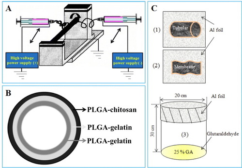
The membranes or electrospun tubes were placed on aluminum foil (figures C (1) and (2)) and the foil was then covered with a beaker (figure (C) (3)); 10 ml of gutaraldehyde 25% solution was added to the beaker, and the scaffolds were incubated at 37 °C for 1 h.
Figure 1. Schematics of double-ejection electrospinning (A), triple-layer artificial blood vessel scaffold (B) and cross-linking process (C).
2.4.3. Tensile strength.
A special technique described in our previous reports was employed to measure tensile strength [Citation27, Citation28]. Specimens (3 mm wide and 5 cm in length) were loaded by 500 g weights. A constant rate of motion was controlled using Helio X Control (UTM) software.
2.4.4. Burst strength.
The lumen of the artificial blood vessel was filled with distilled water, the pressure was increased at a rate of 10 mmHg min−1 using a Keller LEO setup until the first water droplet leaked out, and this final pressure value has been recorded.
2.5. In vitro study
All electrospun membranes were sterilized using 70% EtOH for 30 min prior to in vitro testing, then washed with PBS and suspended in conditioning medium for 15 min.
2.5.1. Cell line and maintenance.
Cell culture studies were carried out using an endothelial cell line derived from a bovine pulmonary artery (CPAE) and fibroblast cells (L929). The CPAE and L-929 cells were subcultured in flasks using RPMI + high glutamine (H/G) and RPMI media that was supplemented with 10% (v/v) FBS and 1% penicillin/streptomycin antibiotics at 37 °C, 95% humidity and 5% CO2 (incubator, ASTEC, Japan). Cells were dissociated with trypsin-EDTA (GIBCO), centrifuged and resuspended in the medium. The culture medium was replaced every 2 days.
2.5.2. Cytotoxicity and cell growth viability.
To evaluate cytotoxicity, the fibroblasts cells (L-929) were seeded in 96-well tissue culture plates at 1000 cells well−1 in 100 μl RPMI. All media contained 10% FBS and all cell lines were incubated overnight. Diluted extract solutions (100 μl) of every fibrous scaffold at various concentrations (100, 50, 25, 12.5 and 0%) were added. The extracted solution was prepared according to the ISO10993-5 standard as described in our previous report [Citation29]. Briefly, membranes (2 × 4 cm2) were immersed in 1 ml media for 3 days, then the extraction media was filtered using a 0.20 μm filter (DISMIC®-25AS). The fibroblast cells were treated for 72 h and then 20 μl of filtered MTT solution (5 mg ml−1 in PBS) was added. The plate was incubated at 37 °C for 3.5 h, the medium was then discarded and 150 μl of DMSO was added to dissolve any remaining formazan crystals.
In the cell proliferation test, the control (tissue culture polystyrene only), the non-crosslinking membranes (PCL–gelatin and PLGA–chitosan membranes) and the crosslinking membranes (cro-PCL–gelatin and cro-PLGA–chitosan) were placed inside the wells (24-well plate) and seeded at a density of 20 000 cells per well. The scaffolds were transferred to a new plate (24 wells) after incubation for 1, 3 and 5 days. Then, 200 μl of the MTT solution was added to the scaffolds and incubated at 37 °C for 3.5 h. After incubation, the supernatant was discarded and the formazan crystals were dissolved in 1 ml DMSO solution. Then, 150 μl of the solution from the 24-well plates was transferred to a 96-well plate. Optical absorbance was measured at 595 nm using an ELISA reader (Turner Biosystems CE, Promega Corporation, USA).
2.5.3. Cell adhesion and proliferation.
L-929 and CPAE were cultured on cro-PLGA–chitosan and cro-PCL–gelatin membranes, respectively, to evaluate the biocompatibility of the artificial blood vessel scaffold, and the results were compared to cell cultures on tissue culture polystyrene (TCPS). After 1, 3 and 5 days of culturing, samples were harvested, rinsed twice with PBS to remove non-adherent cells, fixed with 2% glutaraldehyde for 15 min and washed with D-PBS 2 times (15 min per time). The samples were then dehydrated using a series of solutions as described in our previous report [Citation28]. All samples were air-dried overnight. The dried cells were sputtered with gold and observed by SEM.
3. Results
3.1. Characterizations of morphology of ABV electrospun scaffold
The optimized parameters for fabricating the multilayered ABV electrospun scaffold are listed in the table . Figure shows the process used for electrospinning (A) and construction of artificial blood vessel (B). Two different polymer solutions were electrospun from different sides using two syringes. Their nozzles contained opposite charges and could move in the axial X-direction. The collector, which was connected to the roller, was used to collect the electrospun fibers as shown in figure (a). Each layer of the artificial blood vessel scaffolds was observed by SEM, as shown in figures –.
Figure 2. SEM morphology of the outer layer of the artificial blood vessel: chitosan (a), PLGA (b), PLGA–chitosan (c) and cro-PLGA–chitosan scaffolds (d).
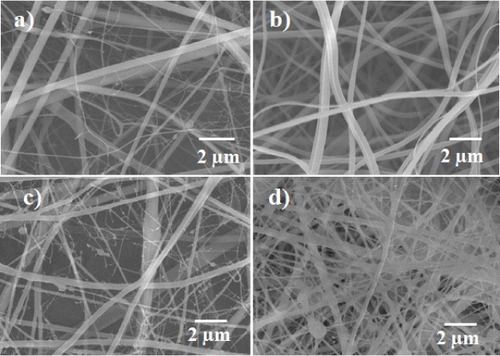
Figure 3. SEM morphology of the intermediate layer of the artificial blood vessel: gelatin (a), PLGA (b), PLGA–gelatin (c) and cro-PLGA–gelatin scaffolds (d).
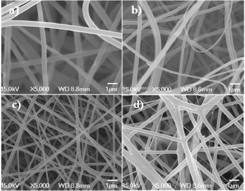
Figure 4. SEM morphology of the inner layer of the artificial blood vessel: gelatin (a), PCL (b), PCL–gelatin (c) and cro-PCL–gelatin scaffolds (d).
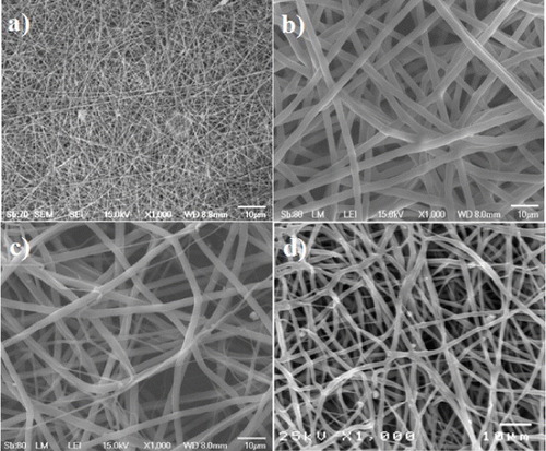
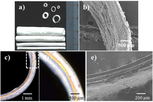
Figure 5. Artificial blood vessels with different inner diameters (a), cross-section (b), the three layers of the PCL–gelatin/PLGA–gelatin/PLGA–chitosan fibrous tube stained in different colors (c), (d) and the bilayers of the PCL–gelatin/PLGA–chitosan fibrous tube (e).
3.1.1. Outer layer (PLGA–chitosan nanofibrous mat).
The optimal electrospinning parameters for each polymer were determined from SEM observations (figure ). Figure (a) shows the fine chitosan fibrous scaffold, which was obtained using a 6% w/v chitosan solution in TFA. The diameter of the chitosan fibers ranged from 200 to 1000 nm, while the PLGA fibers obtained using a 10% w/v PLGA solution in solvent containing THF and DMF (1:1, v/v) ranged from 200 to 700 nm in diameter (figure (b)). Figures (c) and (d) show SEM micrographs of the non-cross-linked (PLGA–chitosan) and cross-linked PLGA–chitosan (cro–PLGA–chitosan) scaffolds, respectively. Figure (c) shows PLGA–chitosan consisting of PLGA and chitosan fibers, which have diameters ranging from a few to 1000 nm. Figure (d) shows the cro-PLGA–chitosan fibers, which ranged in diameter from 500 to 1000 nm. These results reveal that the cro-PLGA–chitosan morphology changed upon cross-linking (figures (c) and 1(d)).
3.1.2. Intermediate layer (PLGA–gelatin electrospun mat).
Figure shows the SEM morphology of the intermediate layer, which consisted of electrospun gelatin, electrospun PLGA, non-crosslinked (PLGA–gelatin) and cross-linked PLGA–gelatin (cro-PLGA–gelatin) electrospun scaffolds. The diameters of the electrospun gelatin fibers vary between 500 and 800 nm (figure (a)), while the diameters of the electrospun PLGA fibers range from 200 to 700 nm (figure (b)). The diameters of mixed electrospun PLGA–gelatin fibers are 200–500 nm (figure (c)). However, the cro-PLGA–gelatin electrospun fibers are thicker than the non-cross-linked fibers (figure (d)).
3.1.3. Inner layer (PCL–gelatin electrospun mat).
SEM was used to obtain more details of the morphology of the gelatin and PCL ultrafine fibers fabricated from a 10 w% polymer solution (figure (a)). Under these conditions, the gelatin and PCL fibers had nanosized diameters. However, when the fibers were fabricated from a 10 w% PCL solution in a solvent containing MC:DMF (2:8) (figure (b)), the diameters of gelatin structures were in the nanoscale range, but the diameter of PCL fibers was 5 μm. Some of the PCL–gelatin (figure (c)) fibers were microns thick, but the diameters of all remaining fibers were in the nanoscale. Figure (d) shows the morphology of cro-PCL–gelatin electrospun fibers, which have diameters ranging from nanometers to micrometers.
3.1.4. Optical and SEM images of PCL–gelatin/PLGA–gelatin/PLGA–chitosan scaffolds.
Electrospun PCL–gelatin/PLGA–gelatin/PLGA–chitosan scaffolds were fabricated with different diameters using double-ejection electrospinning (figure (a)). Figure (b) shows a cross-section of the tubular electrospun scaffold. SEM images reveal that the electrospun fibers had a continuous arrangement from the inside to outside of the blood vessel. The layers of ABV were visualized using the color staining as shown in figure (c). Figure (d) is a magnification of the dashed rectangle in figure (c). The image shows PCL–gelatin, PLGA–gelatin and PLGA–chitosan layers indicated by blue, yellow and orange colors, respectively. The thickness of the scaffold was approximately 600 μm according to SEM observation (figure (b)), making each layer approximately 200 μm thick depending on the concentration of polymers and the electrospinning settings. For example, in the PCL–gelatin layer and the PLGA–layer, the concentrations of the gelatin, PCL and PLGA were similar, so both layers had the same thickness, as shown in figures (c) and (d). In contrast, figure (e) shows the tubular scaffold with separated PCL–gelatin and PLGA–chitosan layers approximately 200 μm in thickness.
3.2. Tensile strength and burst strength
As shown in figure , the cross-linked PCL–gelatin/PLGA–gelatin/PLGA–chitosan electrospun mat (figure (b)) exhibited a higher tensile strength than the non-crosslinked PCL–gelatin/PLGA–chitosan electrospun mat (figure (a)). For example, the strain in curve (b) increased by more than 100% relative to the strain in curve (a), and the stress increased by about 0.5 MPa. These results indicate that the chitosan–chitosan and gelatin–gelatin fibers interacted and bonded during the cross-linking process. Previous reports described a phenomenon in which the fibers were curled and conglutinated with each other after cross-linking [Citation26, Citation30]. The inset images show the morphology of the ABV scaffold before and after cross-linking at the failure section. No differences in the overall structure were observed before (figure (a2)) and after (figure (b2)) cross-linking. As shown in figure (b1), the fibers arranged in a straight line before breaking. Figure (b2) shows the structure of the fiber membrane after the breakage. These results demonstrate that the cross-linked scaffold had a higher strength and lower flexibility than the non-cross-linked scaffold.
Figure 6. Stress–strain curves and corresponding SEM morphology of PCL–gelatin/PLGA–gelatin/PLGA–chitosan ABV scaffold: non-cross-linked (a1-2) and cross-linked (b1-2).
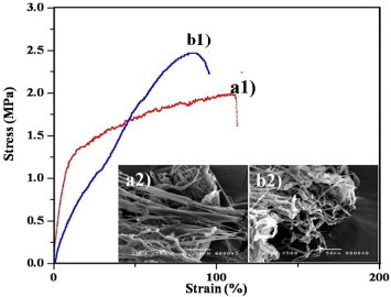
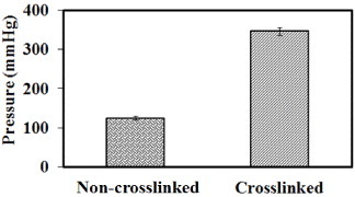
Figure shows the liquid strength of the tubular scaffold when an intermediate pressure was applied. The cross-linked scaffold exhibits a higher liquid strength than the non-cross-linked scaffold, which was expected since the pore size of the electrospun mat decreased (figures –). United States Patent 5549664 describes an ABV that displayed a liquid strength of 300 mmHg for 24 h. In this study, the cross-linked ABV had a liquid strength of approximately 340 mmHg for more than 1 h, which is beneficial for implantation applications.
Figure 7. Burst strength of non-cross-linked and cross-linked PCL–gelatin/PLGA–gelatin/PLGA–chitosan scaffolds.
3.3. In vitro study
3.3.1. Cytotoxicity of triple-layer materials.
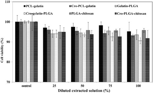
Figure shows the cytotoxicities of the PCL–gelatin, gelatin–PLGA and PLGA–chitosan membranes as assessed by the MTT assay. ISO 10993–5 specifies the incubation procedure of cultured cells in contact with a device or with extracts of a device either directly or through diffusion. In this examination, the extraction medium was used to evaluate the cytotoxicities of non-cross-linked membranes (PCL–gelatin, gelatin–PLGA and PLGA–chitosan membranes) and cross-linked membranes (cro-PCL–gelatin, cro-gelatin–PLGA and cro-PLGA–chitosan). According to ISO 10993–5, these results indicate that the co-components are non-toxic and have excellent biocompatibility, enabling cell viability of higher than 90% for the 100% extracted solution. Equally notable, the values for the 50% extracted solution were similar to those for the 100% extracted solution.
Figure 8. Cytotoxicity of electrospun PCL–gelatin, cro-PCL–gelatin, gelatin–PLGA , cro-gelatin–PLGA, PLGA–chitosan and cro-PLGA–chitosan scaffolds.
3.3.2. Cell proliferation and attachment.
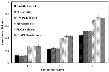
The effect of the cross-linking process on cell proliferation was examined for PLGA–chitosan, cro-PLGA–chitosan and TCPS, as well as for endothelial cells seeded on PCL–gelatin, cro-PCL–gelatin and TCPS. Figure shows the results for 1, 3 and 5 days of cell incubation, assessed by MTT assay. After 3 and 5 days, cellular growth on the PLGA–chitosan and on the cro-PLGA–chitosan membranes increased 3 and 7 times, respectively, compared to 1 day of incubation. In the case of endothelial cells, after 3 and 5 days, cellular growth on the PCL–gelatin and cro-PCL–gelatin membranes increased 2 and 5 times, respectively, compared to 1 day of incubation. In the diagram, endothelial-ctrl and fibroblast-ctrl are the optical densities of the endothelial cells and fibroblast cells that grew only on the TCPS. The results show that cross-linking has no effect on the cell proliferation.
Figure 9. Optical absorbance of fibroblast cells seeded on PLGA–chitosan, cro-PLGA–chitosan and TCPS or endothelial cells seeded on PCL–gelatin, cro-PCL–gelatin and TCPS after 1, 3 and 5 days of incubation.
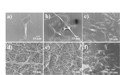
The cell proliferation results were confirmed by SEM observations, as shown in figures and . These figures show cellular attachment and proliferation of L-929 mouse fibroblast cells under static seeding on both PLGA–chitosan electrospun fibers and TCPS. Five days after cell seeding, the cells were well spread on the scaffolds. Cell proliferation on the PLGA–chitosan electrospun mat was determined after 1, 3 and 5 days of incubation, and the results are shown in figures (d), (e) and (f)), respectively. In the case of PLGA–chitosan, 1 day after seeding (figure (d)), the cells had efficiently proliferated, were uniformly spread and covered the entire surface of the biomaterials. The same trend was observed on the positive control surface of TCPS. The presence of lamellapodia and an interlaced fibrous network indicated good cell adhesion. After 3 (figure (e)) and 5 (figure (f)) days, cells covered the entire surface of the control and electrospun mats. A comparison between figures (d)–(f) and figures (a)–(c) reveals that cells efficiently grew on both PLGA–chitosan and TCPS. To assess cell proliferation and cell attachment on the inner surface, CPAE cells were seeded on the PCL–gelatin and TCPS. As shown in figure , the endothelial cells proliferated after 1, 3 and 5 days of incubation. The endothelial cells covered the entire surface of the PCL–gelatin electrospun fiber mat after 5 days of incubation. Endothelial cells interconnect [Citation30] and can cover a very large surface area. Therefore, cro-PCL–gelatin was covered by endothelial cells, as shown in figure (f). By comparing figures (d)–(f), we can see that the cells were rapidly proliferating after every 2 days of incubation. In addition, by comparing figures (d)–(f) and figures (a)–(c), cell growth was found to be the same on cro-PCL–gelatin and TCPS.
Figure 10. SEM morphology of fibroblast cells seeded on TCPS ((a), (b and (c)) and on cross-linked electrospun PLGA–chitosan scaffolds ((d), (e) and (f)) after 1, 3 and 5 days of incubation.
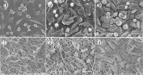
Figure 11. SEM morphology of endothelial cells seeded on TCPS ((a), (b) and (c)) and on cross-linked PCL–gelatin scaffolds ((d), (e) and (f)) after 1, 3 and 5 days of incubation.
4. Discussion
Individual polymers have a limited number of functions for biomedical applications [Citation19]. However, graft-polymerization can be used to enhance the overall properties of individual components of a new polymer, thereby improving biocompatibility [Citation18, Citation31]. The double-ejection electrospinning method has one distinct advantage over other approaches: it allows easy mixing of polymers [Citation19]. The major issue with electrospinning is the fabrication conditions, which can significantly affect the resulting structure of the scaffold [Citation32]. For the double-ejection electrospinning method used in this study, two pumps have been used, one charged positively and the other negatively. The negatively charged pump spun very fine fibers for chitosan and gelatin, in contrast to the positively charged pump. Therefore, the negatively charged pump was used to spin chitosan and gelatin. The maximum distance for both nozzles was 50 cm and the distance between nozzles needed to be optimized. The distances used in this study are summarized in table . The morphology of the mixed electrospun polymers is shown in figures –. The ABV cross-sectional images showed that the inner and outer layers were not separated because they were fabricated using a new technology, which involved three layers and double-ejection electrospinning. Meanwhile, the bilayers PCL–gelatin and PLGA–chitosan were separated as shown in figure (e). Using this approach, the PCL–gelatin/gelatin–PLGA/PLGA–chitosan ABV scaffold was successfully fabricated using a linking method. Specifically, the inner layer was fabricated from PCL–gelatin, with the PCL solution located at the positively charged nozzle and the gelatin solution located at the negatively charged nozzle. The intermediate layer (PLGA–gelatin) was then electrospun by changing the PCL solution to a PLGA solution. Finally, PLGA–chitosan was deposited by switching the gelatin solution to a chitosan solution. A previous study also utilized electrospinning to fabricate an artificial blood vessel with two separate layers [Citation9]. In this work, the copolymer was sprayed using PCL–gelatin and PLGA–chitosan connected by a middle layer (PLGA–gelatin), as shown in figures (b)–(d). This architecture may be superior because the middle layer can support both the inner and outer layer in addition to acting as a buffer between these two layers. After the multilayer scaffold was fabricated, the structure was cross-linked. The tensile strength and liquid strength were higher in the cross-linked than non-cross-linked scaffold as shown in figures and .
The MTT assay is a rapid, standardized, sensitive and inexpensive method to determine whether materials contain significant quantities of biologically harmful components. Therefore, it was employed in this investigation to examine the toxicity of the components used in the fabrication of the scaffold. Figure indicates that that the cross-linking method outlined in figure (C) would be a safe and easy to control process when using glutaraldehyde gas instead of liquid. Glutaraldehyde gas has been commonly used to cross-link protein crystals in the fields of structural biology and crystallization [Citation33, Citation34], allowing to limit polymerization [Citation34]. In this investigation, glutaraldehyde gas was used because the –CHO groups of the free glutaraldehyde crosslink only with –NH2 groups on the surface of gelatin/chitosan electrospun fibers. Thus, only the surface of gelatin/chitosan electrospun fibers is polymerized, preserving the biocompatibility of gelatin/chitosan and the flexibility of the electrospun scaffold. The MTT result specifically showed that all electrospun PCL–gelatin, cro–PCL–gelatin, gelatin–PLGA, cro-gelatin–PLGA, PLGA–chitosan and cro-PLGA–chitosan membranes were non-toxic and had excellent biocompatibility, enabling over 90% cell viability in the 100% extract medium. According to previous studies, a blood vessel structure involves three layers of cells such as endothelial cells, smooth muscle cells and fibroblast cells [Citation35]. Therefore, the scaffold investigated in this study was examined with different cells on different layers. The fibroblast cells (L-929) and endothelial cells (CPAE) proliferated on the outer-layer materials (PLGA–chitosan and cro-PLGA–chitosan) and inner-layer materials (PCL–gelatin and cro-PCL–gelatin), respectively, as shown in figure [Citation19, Citation20]. The optical density data showed that cell viability increased with increasing incubation time for either non-cross-linked or cross-linked membranes, and by comparing these results we conclude that cross-linking was a non-toxic process. Figure provides more details on the growth and biocompatibility of the L-929 cells on the outer layer (PLGA–chitosan electrospun mat). The cells adhered to the fibrous mat after 1 day (figure (d)), became elongated after 3 days (figure (d)) and covered the entire PLGA–chitosan surface after 5 days of incubation (figure (f)). In addition, the shape of the CPAE changed from rounded to elongated, and growth after 1 day (figure (d)) was observed on the PCL–gelatin fibrous mat. After 3 and 5 days of incubation, CPAE proliferated and covered the entire surface of the PCL–gelatin composite (figures (e) and (f)). The combined results on cell attachment, cell proliferation and optical density demonstrated that the ABV scaffold had excellent cell proliferation properties.
5. Conclusions
PCL–gelatin/PLGA–gelatin/PLGA–chitosan scaffolds composed of fibers with different diameters have been fabricated using the double-ejection electrospinning method. The cross-linked PCL–gelatin/PLGA–gelatin/PLGA–chitosan electrospun scaffolds satisfied three requirements to artificial blood vessels: flexibility, resistance to intermediate pressure, and the ability to promote cell growth and proliferation. In addition, the MTT assay and SEM observations demonstrated that the ABV was biocompatible for both fibroblast cells and endothelial cells. The morphology of endothelial cells and fibroblasts indicated that they responded well on the electrospun tube scaffolds and showed good cellular attachment and proliferation. In addition, the composite ABVs displayed high tensile strength (2.3 MPa of stress and 100% of strain) and liquid strength (340 mmHg), which is important for implantation applications. The use of an electrospinning array to form multicomponent nanofibrous membranes will lead to the creation of novel scaffolds for ABVs.
References
- SeifalianA MTiwariAHamiltonGSalacinskiH J2002 Artif. Organs 26 307 10.1046/j.1525-1594.2002.06841.x
- KumarT R SKrishnanL K2001 Biomaterials 22 2769 10.1016/S0142-9612(01)00020-5
- WilliamsonM RBlackRKieltyC2006 Biomaterials 27 3608 10.1016/j.biomaterials.2005.06.018
- SipehiaRMartucciGLipscombeJ1996 Artif. Cells Blood Substit. Immobil. Biotechnol. 24 51 10.3109/10731199609117431
- ChandyTDasG SWilsonR FRaoG H R2000 Biomaterials 21 699 10.1016/S0142-9612(99)00231-8
- KirklinJ WBarratt-BoyersB G1993 Cardiac Surgery Barratt-BoyersB GKirklinJ W New York Churchill-Livingstone p 861
- ZhangW JWeiLCuiLCaoY2007 J. Cell. Mol. Med. 11 945 10.1111/j.1582-4934.2007.00099.x
- DuanBYuanXZhuYZhangYLiXZhangYYaoK2006 Eur. Polym. J. 42 2013 10.1016/j.eurpolymj.2006.04.021
- VazC Mvan TuijlSBoutenC V CBaaijensF P T2005 Acta Biomater. 1 575 10.1016/j.actbio.2005.06.006
- KimM JKimJ HYiGLimS HHongY SChungD J2008 Macromol. Res. 16 345 10.1007/BF03218527
- OhS HParkIKimJ MLeeJ H2007 Biomaterials 28 1664 10.1016/j.biomaterials.2006.11.024
- RaiBTeohS HHutmacherD WCaoTHoK H2005 Biomaterials 26 3739 10.1016/j.biomaterials.2004.09.052
- TangZ GHuntJ A2006 Biomaterials 27 4409 10.1016/j.biomaterials.2006.04.009
- ZhuYLeongM FOngW FChan-ParkM BChianK S2007 Biomaterials 28 861 10.1016/j.biomaterials.2006.09.051
- KimC HKhilM SKimH YLeeH UJahngK Y2006 J. Biomed. Mater. Res. B 78B 283 10.1002/(ISSN)1552-4981
- ChongE JPhanT TLimI JZhangY ZBayB H2007 Acta Biomater. 3 321 10.1016/j.actbio.2007.01.002
- KohH SYongTChanC KRamakrishnaS2008 Biomaterials 29 3574 10.1016/j.biomaterials.2008.05.014
- MaZHeWYongTRamakrishnaS2005 Tissue Eng. 11 1149 10.1089/ten.2005.11.1149
- DuanBWuL LYuanX YHuZLiX LZhangYYaoK DWangM2007 J. Biomed. Mater. Res. A 83 868
- WuLLiHLiSLiX RYuanX YLiX LZhangY2010 J. Biomed. Mater. Res. A 92 563
- DengCLiFMayGRuelMSuuronenE J2010 Macromol. Symp. 297 138 10.1002/masy.v297.1
- WangXMarkitieA APaloheimoK STuomiJPaloheimoMSuiS C2011 Adv. Polym. Technol. 30 163 10.1002/adv.v30.3
- HanJLazaroviciPPomerantzCChenX SWeiYLelkesP I2011 Biomacromolecules 12 399 10.1021/bm101149r
- NguyenT-HLeeS-JMinY KLeeB-T2011 Korean J. Mater. Res. 21 125 10.3740/MRSK.2011.21.2.125
- KhilM SBhattaraiS RKimH YKimS ZLeeK H2005 J. Biomed. Mater. Res. B 72 117 10.1002/(ISSN)1097-4636
- NguyenT-HLeeB-T2010 J. Biomed. Sci. Eng. 3 1117 10.4236/jbise.2010.312145
- NguyenT-HLeeK-HLeeB-T2010 Mater. Sci. Eng. C 30 944 10.1016/j.msec.2010.04.012
- NguyenT-HLeeB-T2010 J. Mater. Sci.; Mater. Med. 21 1969 10.1007/s10856-010-4048-y
- KimY-HLeeB-T2011 Sci. Technol. Adv. Mater. 12 035002 10.1088/1468-6996/12/3/035002
- WilhelmIFarkasA ENagyosziPVaroGBalintZVeghG ACouraudP ORomeroI AWeksierBKrizbalIA2007 Phys. Med. Biology 52 6261 10.1088/0031-9155/52/20/012
- MoffattSCristianoR J2006 Int. J. Pharm. 317 10 10.1016/j.ijpharm.2006.04.011
- SchiffmanJ DSchauerC L2007 Biomacromolecules 8 594 10.1021/bm060804s
- LustyC1999 J. Appl. Crystallogr. 32 106 10.1107/S002188989801053X
- SalemMMauguenYPrangeT2010 Acta Crystallogr. F 66 225 10.1107/S1744309109054037
- LaredoJXueLHowardP Greisler 2008 Encyclopedia of Biomaterials and Biomedical Engineering 2nd edn. vol. 4 WnekG EBowlinG L London Informa Healthcare p 2997