Abstract
We investigated the strengthening mechanism of laser shock processing (LSP) at high temperatures in the K417 nickel-based alloy. Using a laser-induced shock wave, residual compressive stresses and nanocrystals with a length of 30–200 nm and a thickness of 1 μm are produced on the surface of the nickel-based alloy K417. When the K417 alloy is subjected to heat treatment at 900 °C after LSP, most of the residual compressive stress relaxes while the microhardness retains good thermal stability; the nanocrystalline surface has not obviously grown after the 900 °C per 10 h heat treatment, which shows a comparatively good thermal stability. There are several reasons for the good thermal stability of the nanocrystalline surface, such as the low value of cold hardening of LSP, extreme high-density defects and the grain boundary pinning of an impure element. The results of the vibration fatigue experiments show that the fatigue strength of K417 alloy is enhanced and improved from 110 to 285 MPa after LSP. After the 900 °C per 10 h heat treatment, the fatigue strength is 225 MPa; the heat treatment has not significantly reduced the reinforcement effect. The feature of the LSP strengthening mechanism of nickel-based alloy at a high temperature is the co-working effect of the nanocrystalline surface and the residual compressive stress after thermal relaxation.
1. Introduction
Laser shock processing (LSP) has been widely studied for its significant increase in both the fatigue strength and the life span of metal, which therefore solves the problem of high cycle fatigue (HCF) breaking of aircraft engines, by forming a considerable residual compressive stress on the surface of metal through the action of a laser shock wave [Citation1, Citation2]. According to numerous shock simulations and experiment reports, LSP enhancement in the fatigue strength of materials is largely due to the existence of residual compressive stress. Montross et al [Citation3] give an overview of the strengthening mechanism of LSP and argue that it is the residual compressive stress formed by the LSP that improves the fatigue resistance performance. The impact of residual compressive stress on material fatigue performance can be explained through an analysis of its effect on the propagation and closure of cracks, or by looking at the average stress [Citation4]. The strengthening mechanism based on the residual compressive stress has been applied to the LSP of the typically metallic materials of aircraft engines including titanium alloy [Citation5], stainless steel [Citation6, Citation7], aluminum alloy [Citation8, Citation9] and magnesium alloy [Citation10].
However, the residual compressive stress shows relaxation due to the thermal effect [Citation11, Citation12] when LSP is applied to an aircraft engine’s high temperature components. In this case, the LSP effect is weakened according to the mechanism of residual compressive stress strengthening. Therefore, the application of LSP in the high temperature service is an important issue. The LSP will not only form a large numerical residual compressive stress on the surface of the material, but it will also form a severe plastic deformation on the surface of the material [Citation13]. When both a high density of dislocations and grain refinement were induced in the surface deformation layer, it improved the mechanical properties.
In recent years, the research on the changes of a material’s microstructure caused by LSP has attracted considerable attention. Ye et al [Citation14] concluded that the nanostructure and amorphization at the surface of bimodal grains are induced by LSP; further, that deformation twins are generated at the material’s subsurface. Shehadeh et al [Citation15] investigated the ultra-short pulse shock wave propagation, the plastic deformation and the evolution of dislocations in single crystal coppers with different orientations under a high strain rate. Their results showed that the dislocation density is proportional to the pulse duration and sensitive to the crystal orientation. Altenberger et al [Citation16] investigated the nanocrystalline surface and whether the high density of dislocations in Ti–6Al–4 V titanium alloy are induced by LSP; these remain fairly stable even after being cycled at 450–550 °C, which is beneficial to the fatigue strength of Ti–6Al–4 V. Ding and Shin [Citation17] studied the prediction of the microstructural evolution of metallic components subjected to single or multiple LSP impacts.
In this paper, we studied the aero engine turbine blade material K417 and observed the microstructure change on the surface of this nickel-based alloy after LSP treatment. We found that the nanocrystalline surface of a nickel-based alloy is formed when the shock wave pressure reaches a value that is higher than a certain threshold value. We especially focused on the effect of the nanocrystalline surface on the mechanical properties of a nickel-based alloy in a high temperature environment. Additionally, the nanocrystalline surface has good thermal stability.
To this end, the strengthening mechanism of a nickel-based alloy in a high temperature environment is revealed. The feature of the LSP strengthening mechanism is the co-working effects of the nanocrystalline surface and the residual compressive stress after thermal relaxation.
2. Experiments and methods
2.1. Materials
The experimental material is the nickel-based alloy K417, which has been widely applied in the turbine blades of aero engines. The chemical composition of thenickel-based alloy K417 is shown in table . Its grains are composed of a coarse dendritic structure, in which the dendritic branch is a γ solid solution with a large amount of the γ′ strengthening phase distributed among the dendrite. Eutectic and carbide exist among the dendrite (γ + γ′), such as TiC. The γ′ phase is the strengthening phase of the nickel-based alloy K417, which is distributed uniformly in the alloy. Under normal heat treatment, it is mainly distributed in a circular or cuboid shape, as is shown in figure .
Figure 1. The γ and γ′ phase of K417.
Table 1. Composition of the nickel-based super alloy K417.
2.2. The principle and experimental procedure of LSP
Prior to the LSP treatment, the sample surface should be polished with SiC paper, with the roughness ranging from 500 to 2400, to make the surface roughness Ra 0.3 μm. LSP experiments were performed using a Q-switched Nd:YAG laser operating at a 1 Hz repetition rate with a wavelength of 1064 nm and the full width at half maximum (FWHM) of the pulses at about 20 ns. The LSP parameters are shown in table . The lapping rate is the laser spot overlapping rate. Samples were submerged in a water bath, then processed by LSP. A water layer with a thickness of about 1 mm was used as the transparent confining layer and professional aluminum tape with a thickness of 100 μm was used as the absorbing layer. The application of the protective layer is to protect the surface of the metal material from direct ablation and to promote a better coupling with the laser energy. The water confinement is to confine the diffusion of the high temperature plasma produced by laser irradiation and to increase the pressure of the shock wave [Citation18]. Figure (a) also shows a schematic illustration of the LSP set-up used in this work. Each laser shock induces the plastic deformation with an ultra-high strain rate (106 s−1) in the surface, as is schematically shown in figure (b).
Figure 2. Schematic diagram of LSP: (a) the processing set-up of LSP; (b) the localized plastic deformation in the surface layer by the impact of the laser shock plasma wave.
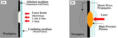
Table 2. Laser shock parameters.
In this paper, the samples were laser shock peened at the same layer, but with impact times of 1/5, respectively. During multiple LSP impacts, the laser beam was perpendicular to the surface of the sample and the multiple laser pulses impacted at the same location on the sample; the aluminum tape was replaced after each impact during multiple LSP impacts.
2.3. Heat treatment testing method
The service ability temperature of the nickel-based alloy K417 is 850 °C in an aero engine turbine blade. The heat treatment experiment was designed to imitate an aero engine’s high temperature environment.
The samples of LSP treatment were vacuum annealed for 10 h at 530, 700 or 900 °C using a heating rate of 20 °C min−1, a pressure of 3 × 10⁻³ Pa and furnace cooling.
2.4. Measurement equipment and methods
The microstructure change of the different layers in the treated samples subjected to LSP impacts was characterized by transmission electron microscopy (TEM). The TEM foils at different depths were made as follows: TEM foils from a given depth below the surface were prepared by a combination of single and twin-jet electropolishing. We used the observation equipment Tecnai G2 F20 S-Twin with experimental parameters: FEG (field emission gun): 200 kV; point resolution: 0.24 nm; line resolution: 0.102 nm; information resolution: 0.14 nm.
The cross-section of samples used for the Vickers microhardness test, as a function of heat treatment, were cut and a perpendicular cube was made; then the samples were subjected to several successive steps of grinding and polishing. The microhardness was measured on the cross-sections of specimens using an indentation load of 500 g at the transverse section, with a dwell time of 10 s and with the MVS-1000JMT2 microhardness tester.
X-ray diffraction (XRD) analysis was carried out with an MFS-7000 setup using Cu Kα radiation, with a take-off angle of 6°. The generator settings are 40 kV and 35 mA. The diffraction data are collected over a 2θ range of 30–80°, with a step width of 0.02° and a counting time of 5 s per step.
The residual stresses after LSP impacts are determined by x-ray diffraction with the sin2 w method. Prior to the measurement of the residual stress along the depth direction, the electropolishing material removal method was used. And the surface residual stresses relaxation profiles in different high temperature environments were determined after LSP treatment.
2.5. HCF method
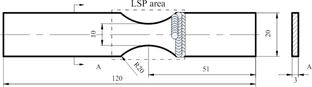
The largest single cause of component failures in modern military aircraft gas turbine engines is HCF, since they accumulate stress cycles at a prodigious rate in a high temperature environment. The vibration fatigue test was designed; the shape and size of the test sample is shown in figure . The dashed rectangular part in the specimen is the original crack zone where the LSP treatment was carried out. In order to study the influence of thermal stability of LSP, we continued the vibration fatigue performance comparison between the ‘LSP’ and ‘LSP + heat treatment’, in which an up-and-down method was adopted.
Figure 3. Dimensions of the test specimen (in mm).
3. Results and discussions
3.1. Fatigue performance
An up-and-down method was used in the fatigue experiment in which ten specimens were selected for each processing status. When the cumulative excitation frequency drops to 3% below the cycle index number 107, the test stops and the specimen block can be defined as a ‘break’; when the vibration frequency decreases cumulatively below the value of 3 Hz, with the number 107 of the cycle index, the test stops and the specimen block can be defined as ‘exceeded’. When the proof stress of the specimen block exceeds a given value of 10% with a cycle index number of 25%, the test stops and if a crack appears on the gripping position of the specimen block, the test is canceled. Figure shows a photograph of the vibration experiment arrangement. The exciter provides vibration displacement at the resonance frequency of the sample mounted on it. The displacement and stress are monitored by the displacement sensor and the strain gauge. Strain gauges should be used to establish test stress levels by calibrating to the tip of the deflection. Gauges should be placed on areas of interest and reference locations on the corresponding part. If the highest stressed areas cannot be strain gauged, strain gauges should be used in conjunction with a finite element model to predict peak stresses. Before the test, the relation between the displacement at the tip of the sample and the maximum stress is determined. The vibration fatigue test of K417 samples was conducted under atmospheric conditions and at room temperature, the equipment is shown in figure .
Figure 4. Vibratory experiment system.
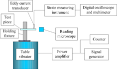
Figure 5. Clamp and measurement.
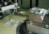
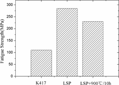
Figure shows the vibration fatigue strength of K417 alloy samples with different processing states. Compared with the original sample, the LSP can effectively increase the vibration fatigue strength from 110 to 285 MPa. After heat treatment at 900 °C per 10 h, the vibration fatigue strength is 230 MPa, slightly lower than before: heat treatment does not obviously reduce the strengthening effectiveness of LSP.
Figure 6. Vibration fatigue strength of K417 alloy before and after LSP processing.
3.2. Residual compressive stress induced by LSP and its thermal relaxation
The residual compressive stress distributions as a function of depth are presented. It can be noted from figure that the significant residual compressive stresses mainly exist in near-surface regions for all cases and that the subsurface has the maximum values of residual compressive stresses. Cellard et al [Citation19] investigated the influence of the process parameters of LSP on specimens made of the titanium alloy Ti-17. A typical residual stress profile is presented as a function of the depth. The maximum residual compressive stress is induced at the subsurface by using all the process parameters.
Figure 7. Residual stress profiles of the hardening layer after multiple LSP impacts at 6 GW cm−2.
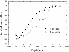
When laser power density is about 6 GW cm−2, the surface residual compressive stress for a single LSP impact is 583 MPa, for three LSP impacts it is 624 MPa. Meanwhile, the peak residual compressive stress for a single LSP impact is 667 MPa; it is 702 MPa after three LSP impacts. It can be seen that both the surface and peak residual compressive stress are increased by 7 and 5% when the impact occurrence increases from singular to three. The depth of residual compressive stress reaches about 800 μm in a single impact; as a result of three LSP impacts on the sample surface, the depth reaches about 1000 μm, which has apparently increased by nearly 25%. The cumulative impacts have a very superficial effect on the residual compressive stress levels in the superficial layers. Therefore, it can be concluded that impact occurrence has an important influence on the residual compressive stress. The residual compressive stress may counteract some or all of the tensile stress, decrease the crack propagation rate, effectively reduce the stress intensity factors, enhance the fatigue crack closure effect and increase the critical stress of crack propagation, thus improving the fatigue performance of metal materials. However, the residual compressive stress becomes relaxed under the thermal effect or cycle loading. In order to assess the residual compressive stress thermal relaxation of LSP, heat treatment has been held after LSP.
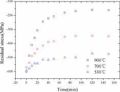
As shown in figure , the surface residual compressive stress induced by the single LSP impact gradually decreases with the thermal holding time at different temperatures. The temperature has a significant influence on the residual compressive stress. After (530/700/900) °C for 150 min heat treatment, the surface residual compressive stress has slightly declined from (595/568/582) to (482/347/161) MPa. It can be seen that the surface residual compressive stress is released by 19 and 39% when the temperature increases from 530 to 700 °C. When the temperature increases to 900 °C, 72% of the surface residual compressive stress is relaxed. During the first 30 min of 900 °C heat treatment, the residual compressive stress releases quickly, with 60% of the residual compressive relaxed; then the residual compressive stress continues to reduce, but the decreased trend gradually slows down, until basically becoming stable. However, the fatigue experiments show that, after the heat treatment of 900 °C per 10 h, the K417 alloy fatigue strength with LSP is greatly improved. The strengthening effectiveness of LSP after the heat treatment cannot only be effectively explained in the light of the residual compressive stress strengthening mechanism.
Figure 8. Relaxation of surface residual compressive stress in K417 alloy.
3.3. The surface nanocrystallization induced by LSP and its strengthening mechanism
The x-ray diffraction (XRD) qualitative analysis of phases of the K417 alloy before and after LSP was conducted, as is shown in figure .
Figure 9. XRD analysis of surface microstructure of K417 alloy before and after LSP: (a) XRD patterns; (b) FWHM of the (220) peak at different LSP impacts.
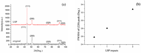
As seen in figures (a) and (b), without regarding the influence of instrumental broadening, the Bragg diffraction peak of K417 alloy has broadened. The FWHM of (220) peak of K417 alloy is 2.6°. After one impact, its FWHM becomes 2.8°, an improvement of 8%; after three impacts, the FWHM becomes 3.3°, an improvement of 27%. Increasing the number of impacts will improve the FWHM of (220) peak of K417 alloy, which indicates that grain refinement, lattice deformation and an increase of microstress have occurred in the surface layer of the nickel-based alloy. Figure shows the TEM images of the K417 alloy at different depths after LSP.
Figure 10. TEM images of K417 alloy at different depths after LSP: (a) the nanocrystalline surface; (b) the selected-area electron diffraction pattern for the nanocrystalline surface; (c) dislocation cell at a depth of 1–5 μm; (d) high density of dislocations pileup at a depth of 1–5 μm.
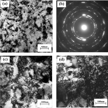
As is shown in figures (a) and (b), the laser shock has formed a 30–500 nm nanocrystalline layer with a thickness of 1 μm on the surface of the K417 alloy. The diffraction pattern is dominated by circles, which indicates the random orientation of the nanocrystals. Dislocation activity is the main formation reason for the grain refinement mechanism induced by a laser shock wave. Meyers [Citation20] put forward the homogeneous nucleation theory for dislocation deformation. When the deviatoric elastic stresses at the front reach a critical level, dislocations are generated. According to the Fabbro shock wave pressure calculation model and the polyvinylidene fluoride piezoelectric film experiment, when the laser power density is about 6 GW cm−2, the surge pressure induced by the laser is about 4 GPa, which is larger than the threshold pressure and meets the dislocation theory by Meyers. With the rise of the wave pressure, the high density of dislocations change into dislocation walls and dislocation cells by slip accumulation, as is shown in figures (c) and (d). Therefore, grains can be refined with the formations of dislocation walls and tangles.
The surface nanostructure formed in this way is different from the surface nanocrystallization by mechanical processing mechanisms, such as surface mechanical attrition treatment (SMAT) [Citation21, Citation22]. The principle of SMAT is that some grains in the surface layer may reach a critical resolved shear stress with a single shot, so the slip system is activated and then generates dislocations. If the directions of the following shots are changed, other slip systems of the grains will be activated, which will lead to grain refinement. This process involves hundreds of thousands of shots. The accumulation of plastic deformation expands gradually to the inner layer of the material to refine grains. In this process, the deformation rate is low [Citation23], while the surface grain refinement induced by laser plasma shock wave is plastic deformation at a very high rate [Citation13].
The nanostructure of the surface and the grain size gradient along the depth induced by LSP could effectively improve the fatigue life of metallic materials. Since most fatigue cracks initiate from the surface and propagate to the interior, a component with a nanostructured surface layer and coarse-grained interior is expected to have highly improved fatigue properties because both fatigue-crack initiation and propagation are inhibited by fine grains near the surface and coarse grains in the interior, respectively. It has been shown in the following aspects:
| (1) | The strengthening effect of the nanocrystalline surface and high density of dislocations. The sizes of surface nanocrystals are small and even. During crack initiation, the crack driving force can be borne by more fine grains. Relatively, strain between the grain interior and the grain boundary is smaller and the stress concentration is relatively small. When the materials bear stress evenly, cracks will not easily initiate [Citation24]. During crack propagation, due to the high value of the grain boundary volume fraction in the structure of the nanocrystalline surface, microcracks are blocked at the grain boundary; meanwhile, once the microcracks have passed through the grain boundary, the matrix grains have a high density of dislocations and the extended direction changes, which consumes more energy to restrain the propagation of microcracks. | ||||
| (2) | The elimination of stress concentration by the nanocrystalline surface and the high density of dislocations. The location of the metal surface slip band and the inclusion or the interface of the second phase and the matrix are where the stress concentration is higher; therefore, fatigue cracks usually originate from the surface of the metal parts. After surface nanocrystallization induced by LSP, the surface of the slip band and the second phase interface decrease relatively. The effect of grain refinery reduces the average slip distance and the stress concentration caused by the dislocation on the grain boundaries, thus it helps to inhibit crack initiation. | ||||
| (3) | The inhibition of crack propagation of matrix coarse grains. After surface nanocrystallization of the metal, the matrix parts still keep the original coarse grains, which is helpful to resist crack propagation. Coarse grains may deflect the propagation paths of fatigue cracks by grain boundaries, thus inducing crack closure and decreasing the rate of crack growth. The refined surface grains of the materials can effectively enhance the fatigue-crack-initiation threshold, which keeps the coarse grain state of restraining crack propagation so as to improve its fatigue life [Citation25, Citation26]. | ||||
The LSP will not only form the large numerical residual compressive stress in the material, but will also form the nanocrystalline layer on the surface, under certain treatment parameters.
3.4. The thermal stability of LSP
3.4.1. The nanocrystalline surface.
Generally, the nickel- based alloy is used at a particularly high temperature. Due to the release of the residual compressive stress at thermal effect, the thermal stability of the nanocrystalline surface formed by the laser shock decides whether LSP would be applied to the high temperature components. The surface TEM films have been prepared after the effect of the 900 °C per 10 h heat treatment on the K417 alloy.
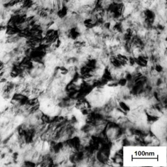
As is seen in figure , comparing the nanocrystalline surface before heat treatment (figure (a)) and after the 900 °C per 10 h heat treatment shows no obvious change of the nanocrystalline surface. The nanocrystalline surface has not grown obviously, which shows comparatively good thermal stability. A test and analysis of the hardness have been carried out to inspect the relationship between the nanocrystalline surface and the mechanical properties after the thermal effect.
Figure 11. Surface microstructure after heat treatment at 900 °C for 10 h (TEM image).
3.4.2. Microhardness.
Hardness is a basic mechanical property of a material and it can be aptly defined as the resistance offered by the material to indentation. Figure shows the Vickers microhardness values in the cross section of the K417 alloy sample, before and after heat treatments. It shows that the laser shock has substantially raised the microhardness of the material. The hardness of the K417 alloy matrix is 380 HV0.2, but the surface hardness after LSP is 445 HV0.2, which has increased by 17%, with impact layers of 1500 μm. After heat treatment, the value of hardness has slightly declined, with a surface hardness of 440 HV0.2, while the relative matrix has increased by 15.7% and the impact depth has reduced to 800 μm. After heat treatment, both the surface hardness and the impact depth have decreased to some extent, while the relative matrix increased substantially, which indicates that the hardness has retained good thermal stability.
Figure 12. Microhardness of K417 alloy in cross section before and after heat treatment.
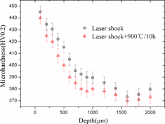
Increasing the dislocation density will improve the hardness of a material. It is known that a laser shock wave will decay inside the material when it impacts on the surface of the material causing the pressure of the shock wave to decrease. A low deformation rate leads to a low dislocation, which means that the hardness decreases as the depth decreases. At the same time, when the laser shock decreases to a certain degree in which it cannot cause distortion among atoms, the hardness will be stable within a certain value. The large numerical value of the residual compressive stress, the nanocrystalline surface and the high density of dislocations, caused by the shock wave, have worked together to increase the hardness of the material. However, under the thermal effect, the residual compressive stress relaxes. While the high density of dislocations and the nanocrystalline surface have good thermal stability, they can only increase the microhardness of K417 alloy within a certain depth.
3.4.3. Reasons for thermal stability.
The nanocrystalline surface formed by LSP has good thermal stability due to the following reasons.
| (1) | The influence of the cold hardening work rate. The cold hardening rate and the thermal stability of materials are closely linked. According to reports [Citation27], the SP cold hardening rate of IN718 nickel-based alloy is up to 40% at the most, but the LSP single shock is less than 1% and will reach up to 5–7% with a small cold hardening rate under repeated shocks. Compared with those traditional surface reinforcement schedules like SP, the LSP, at the lower cold hardening work rate, would produce a higher density dislocation as well as deeper residual stress layers. With the increase of microstrain, the activation energy required for stress release decreases and consequently leads to a better thermal stability. Meanwhile, the higher density dislocation produced by the LSP results in the obvious orientation declination of the grain boundary between the grains. Interacting with the grain boundary, the higher density dislocation will restrict or impede the movements of the grain boundary and consequently delay or prevent the growth of the grains. | ||||
| (2) | The influence of crystal defects. Under the thermal effect, the high density of dislocations produced by a laser shock experience causes the annihilation and rearrangement of nanocrystals, during which lots of energy of the heat treatment has been consumed to cause the decrease in dislocation density. Meanwhile, the higher density dislocation, interacting with the grain boundary, restricts or impedes the movements of the grain boundary and consequently delays or prevents the growth of the grains. | ||||
| (3) | The influence of alloy elements and impurities. The triple line boundary exists in abundance on the nanocrystalline surface of laser-shocked K417 alloy, where the energy is higher than that of the average grain boundaries. Therefore, the impurities or alloying elements are inclined to exist here and to interact with it, when the impurities or alloying elements would spin more effectively on the grain boundaries, with multiple grain boundaries spinning each time. In this way, more energy is required for the grain boundary migration for unit distance in unit area, which results in the poor activity of the grain boundary of the non-elementary substance nanometer sized material, so that the nanocrystalline surface of the laser-shocked K417 alloy has a superior thermal stability. | ||||
4. Conclusions
This paper investigates the strengthening mechanism of LSP and its application in the nickel-based alloy K417 at high temperatures. The main conclusions obtained in this study are as follows.
| (1) | The laser induced high pressure shock wave will lead to an ultrahigh strain rate dynamic response in the material. When the wave reaches a certain critical value, a high density of dislocations will form rapidly on or near the wave front. As the wave pressure rises, the dislocations will move and thus nanocrystals can be formed rapidly. The nanocrystalline surface with a thickness of 1 μm and size of 30–500 nm is formed on the surface of K417 alloy by LSP. | ||||
| (2) | Since the nanocrystalline surface and the microhardness have good thermal stability, the nanocrystalline surface does not grow obviously after the heat treatment of 900 °C per 10 h and the microhardness does not keep the superior thermal stability either. The main reasons for the good thermal stability are the low cold hardening rate of LSP, the very high density of defects and the pinning of impurity elements. | ||||
| (3) | The fatigue experiments show that LSP can improve the fatigue strength of K417 alloy by more than 1.6 times. After a heat treatment of 900 °C per 150 min, the 72% residual compressive stress relaxes, but after a heat treatment of 900 °C per 10 h, the fatigue strength enhances for more than 1.1 times, depending on the matrix. The relatively good thermal stability of the nanocrystalline surface is the primary cause of the fatigue strength increase. | ||||
References
- MaawadEBrokmeierH GWagnerLSanoYGenzeldCh 2011 Investigation on the surface and near-surface characteristics of Ti–2.5Cu after various mechanical surface treatments Surf. Coat. Technol. 205 3644 3650 3644–50 10.1016/j.surfcoat.2011.01.001
- Hatamleh LyonsJFormanR 2007 Laser and shot peening effects on fatigue crack growth in friction stir welded 7075-T7351 aluminum alloy joints Int. J. Fatigue 29 421 434 421–34 10.1016/j.ijfatigue.2006.05.007
- MontrossC SWeiTYeLGrahamClarkMaiY W 2002 Laser shock processing and its effects on microstructure and properties of metal alloys: a review Int. J. Fatigue 24 1021 1036 1021–36 10.1016/S0142-1123(02)00022-1
- RenX DZhangY KYongzhuoH FRuanLJiangD WZhangTChenK M 2011 Effect of laser shock processing on the fatigue crack initiation and propagation of 7050-T7451 aluminum alloy Mater. Sci. Eng. A 528 2899 2903 2899–903 10.1016/j.msea.2010.12.058
- MaawadESanoYWagnerLBrokmeierH GGenzelC 2012 Investigation of laser shock peening effects on residual stress state and fatigue performance of titanium alloys Mater. Sci. Eng. A 536 82 91 82–91 10.1016/j.msea.2011.12.072
- SanoYObataMKuboTMukaiNYodaMMasakiKOchiY 2006 Retardation of crack initiation and growth in austenitic stainless steels by laser peening without protective coating Mater. Sci. Eng. A 417 334 340 334–40 10.1016/j.msea.2005.11.017
- AltenbergerN I 2007 Comparison of the fatigue behavior and residual stress stability of laser-shock peened and deep rolled austenitic stainless steel AISI 304 in the temperature range 25–600 °C Mater. Sci. Eng. A 465 176 182 176–82 10.1016/j.msea.2007.02.004
- Rubio-GonzálezCOcañaJ LGomez-RosasGMolpeceresCParedesMBanderasAPorroJMoralesM 2004 Effect of laser shock processing on fatigue crack growth and fracture toughness of 6061-T6 aluminum alloy Mater. Sci. Eng. A 386 291 295 291–5
- OchiYMatsumuraTIkarashiTMasakiKKakiuchiTSanoYAdachiT 2010 Effects of laser peening treatment without protective coating on axial fatigue property of aluminum alloy Procedia Eng. 2 491 498 491–8 10.1016/j.proeng.2010.03.053
- LiX CZhangY KChenJ FLuY L 2013 Effect of laser shock processing on stress corrosion cracking behaviour of AZ31 magnesium alloy at slow strain rate Mater. Sci. Technol. 29 626 630 626–30 10.1179/1743284712Y.0000000166
- ZhouZBhamareSRamakrishnanGMannavaS RLangerKWenY HQianDVasudevanV K 2012 Thermal relaxation of residual stress in laser shock peened Ti–6Al–4 V alloy Surf. Coat. Technol. 206 4619 4627 4619–27 10.1016/j.surfcoat.2012.05.022
- ZhouZGillA SQianDMannavaS RLangerKWenY HVasudevanV K 2011 A finite element study of thermal relaxation of residual stress in laser shock peened IN718 superalloy Int. J. Impact Eng. 38 590 596 590–6 10.1016/j.ijimpeng.2011.02.006
- ZhouL CLiY HHeW FHeG YNieX F 2013 Deforming TC6 titanium alloys at ultrahigh strain rates during multiple laser shock peening Mater. Sci. Eng. A 578 181 186 181–6 10.1016/j.msea.2013.04.070
- YeCSuslovSFeiX LChengG J 2011 Fatigue performance improvement in AISI 4140 steel by dynamic strain aging and dynamic precipitation during warm laser shock peening Acta Mater. 59 7219 7227 7219–27 10.1016/j.actamat.2011.07.070
- ShehadehM AZbibH MDiaz de la RubiaT 2005 Multiscale dislocation dynamics simulations of shock compression in copper single crystal Int. J. Plast. 21 2369 2390 2369–90 10.1016/j.ijplas.2004.12.004
- AltenbergerINallaR KSanoYWagnerLRitchieR O 2012 On the effect of deep-rolling and laser-peening on the stress-controlled low- and high-cycle fatigue behavior of Ti–6Al–4 V at elevated temperatures up to 550 °C Int. J. Fatigue 44 292 302 292–302 10.1016/j.ijfatigue.2012.03.008
- DingH TShinY C 2012 Dislocation density-based modeling of subsurface grain refinement with laser-induced shock compression Comput. Mater. Sci. 53 79 88 79–88 10.1016/j.commatsci.2011.08.038
- YangJ MHerY CHanNClauerA 2001 Laser shock peening on fatigue behavior of 2024-T3 Al alloy with fastener holes and stopholes Mater. Sci. Eng. A 298 296 299 296–9 10.1016/S0921-5093(00)01277-6
- CellardCRetraintDFrancoisMRouhaudELe SaunierD 2012 Laser shock peening of Ti-17 titanium alloy: influence of process parameters Mater. Sci. Eng. A 532 362 372 362–72 10.1016/j.msea.2011.10.104
- MeyersM A 1994 Dynamic Behavior of Materials New York Wiley
- SatoMTsujiNMinaminoYKoizumiY 2004 Formation of nanocrystalline surface layers in various metallic materials by near surface severe plastic deformation Sci. Technol. Adv. Mater. 5 145 152 145–52 10.1016/j.stam.2003.10.015
- TaoN RSuiM LLuJLuK 1999 Surface nanocrystallization of iron induced by ultrasonic shot peening Nanostruct. Mater. 11 433 440 433–40 10.1016/S0965-9773(99)00324-4
- TaoN RWangZ BTongW PSuiM LLuJLuK 2002 An investigation of surface nanocrystallization mechanism in Fe induced by surface mechanical attrition treatment Acta Mater. 50 4603 4616 4603–16 10.1016/S1359-6454(02)00310-5
- RolandTRetraintDLuKLuJ 2006 Fatigue life improvement through surface nanostructuring of stainless steel by means of surface mechanical attrition treatment Scr. Mater. 54 1949 1954 1949–54 10.1016/j.scriptamat.2006.01.049
- BagherifardSFernández ParienteIGhelichiRGuaglianoM 2010 Fatigue properties of nanocrystallized surfaces obtained by high energy shot peening Procedia Eng. 2 1683 1690 1683–90 10.1016/j.proeng.2010.03.181
- HicksM AKingaJ E 1983 Temperature effects on fatigue thresholds and structure sensitive crack growth in a nickel-base superalloy Int. J. Fatigue 5 67 74 67–74 10.1016/0142-1123(83)90056-7
- PrevéyP S 2000 The effect of cold work on the thermal stability of residual compression in surface enhanced IN718 20th ASM Materials Solutions Conf. and Exposition 10–12 October St Louis, MO p 426