
Abstract
A composite of graphene and carbon nanotubes has been synthesized and characterized for application as supercapacitor electrodes. By coating the nanostructured active material of Co(OH)2 onto one electrode, the asymmetric supercapacitor has exhibited a high specific capacitance of 310 F g−1, energy density of 172 Wh kg−1 and maximum power density of 198 kW kg−1 in ionic liquid electrolyte EMI-TFSI.
1. Introduction
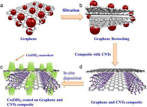
The supercapacitor is a promising energy storage device since it can deliver a power density several orders of magnitude higher than a lithium-ion battery, which has been the most advanced energy storage device up to now [Citation1, Citation2]. In addition, the excellent cycle life and its safety in operation make it highly competitive in many applications such as in electric and hybrid vehicles [Citation3]. Some of the recently developed nanostructured carbon structures, such as carbon nanobeads, carbon nanotubes (CNTs), carbon nanohorns and especially graphene, have a high specific surface area, high electrical conductivity and good chemical stability [Citation4–Citation10]. The theoretical specific surface area of graphene is 2630 m2 g−1, which is much larger than that of the activated carbon and CNTs that are usually used in electrochemical double-layer capacitors, although the Brunauer–Emmett–Teller specific surface area of activated carbon could reach as high as 3000 m2 g−1, largely owing to the presence and contributions of functional groups in activated carbon [Citation3]. Graphene can interface with electrolyte ions on both of its sides and has the best structure for energy storage (figure (a)). However, there are also issues with pristine graphene electrodes. Firstly, the chemically reduced graphene usually has an electrical conductivity of about 100–200 S m−1, which is two orders of magnitude lower than that of conductive single-walled CNTs (usually 10 000 S m−1) [Citation11]. Secondly, like most nanomaterials, graphene is also prone to irreversible agglomeration or to restack into graphite through van der Waals interactions during the drying process that is used to obtain it. In this case, it would be difficult for the electrolyte ions to gain access to the inner layers to form electrochemical double layers if the graphene sheets are stacked together. Instead, the electrolyte ions could only accumulate on the top and the bottom surfaces of the graphene stack, which would then lead to a lower specific capacitance since the stacked material cannot be fully utilized, as illustrated in figure (d) [Citation12]. Thirdly, a graphene electrode cannot function well without a binder, which would usually reduce the specific capacitance.
Figure 1 Schematic of graphene-based electrodes. (a) Single-layer graphene. Single-layer graphene has the highest surface area of 2630 m2 g−1, which can interface with electrolyte ions on both sides of the graphene. (b) Few-layer graphene. Graphene nanosheets are likely to agglomerate through van der Waals interactions during the drying process. It would be difficult for electrolyte ions to access the ultra-small pores, especially for larger ions such as those in an organic electrolyte, or at a high charging rate. (c) Graphene–CNT composite is coated with vertically aligned Co(OH)2 nano-sheets by cathodic in situ deposition to fabricate a graphene–CNT–Co(OH)2 composite. (d) Graphene–CNT composite. CNTs can serve as a spacer between the graphene nanosheets to provide rapid diffusion pathways for the electrolyte ions; moreover, they can increase the electrical conduction. The CNTs also serve as a binder to hold the graphene nanosheets together, preventing the disintegration of the composite in electrolyte.
We have recently studied and developed a graphene–CNT composite with a three-dimensional porous network structure that has exhibited record-high energy density and power density when used in an electrochemical double-layer capacitor [Citation13]. However, the specific capacitance as well as the energy density will be further increased if we can decorate the graphene–CNT composite structure with nanostructured active materials such as transition metal oxides, hydroxides or conductive polymers. Among the active materials, metal oxides and hydroxides have been considered the most promising for electrochemical supercapacitors since they often show an extremely high specific capacitance [Citation14–Citation21]. Cobalt hydroxide (Co(OH)2) is an excellent example material due to its layered structure with large internal spaces for fast insertion and desertion of electrolyte ions [Citation22]. Its high theoretical specific capacitance of 3458 F g−1 has also made it a very attractive active material for pseudocapacitors [Citation8, Citation11, Citation23–Citation27]. However, metal hydroxides often suffer from high electrical resistance because of the chemical nature of the material. In addition, the thick coating of active material also contributes to a poor cyclability.
We therefore designed a Co(OH)2 nano-sheet–decorated graphene–CNT composite structure which is shown schematically in figure . First, we use suspensions of graphene and single-walled CNTs to produce a graphene–CNT composite by sonication and vacuum filtration. The graphene–CNT composite is designed to have high conductivity, chemical stability and a three-dimensional structure with high porosity, as illustrated in figure (d). The porous structure of the graphene–CNT composite is to facilitate the diffusion of the electrolyte into electrodes to provide channels for rapid ion transport. The vertically aligned Co(OH)2 nano-sheets are then coated onto the graphene–CNT composite by electrodeposition. The Co(OH)2-coated graphene–CNT composite electrodes are utilized binder-free. The vertically aligned Co(OH)2 nano-sheets can further shorten the ion diffusion path. The nano-structured active material can also increase the efficiency of usage of materials since only the part within a few nanometers from the surface of the active material can take part in the redox reactions and contribute to the actual device capacitance.
Experimental details
Graphene oxide
Graphene oxide was synthesized using a modified Hummers–Offeman method from graphite in our experiment [Citation28]. Graphite and NaNO3 were first mixed together in a flask before H2SO4 was added to the flask, which was kept and stirred in an ice bath. Potassium permanganate was then added to the suspension. The color of the suspension would become bright brown. After H2O2 was added to dilute the suspension, the mixture was finally washed by rinsing with 5% HCl and demonized water. After centrifugation, filtration and drying in a vacuum, graphene oxide was obtained in the form of a black powder.
Reduction of graphene oxide
The graphene oxide suspension was heated to 100 °C and hydrazine hydrate was added to the suspension. The suspension was then reduced and black powders were collected by filtration. The obtained material was then washed using distilled water again to remove the excessive hydrazine and was redistributed into water for sonication and centrifugation. The final graphene material was collected by vacuum filtration.
Graphene–CNT–Co(OH)2 composite
To make the graphene–CNT–Co(OH)2 composite, graphene and CNTs were first dispersed and mixed in ethanol to obtain a uniform graphene–CNT composite film by vacuum filtration. The electrodeposition of Co(OH)2 nano-sheets was conducted using a three-electrode system, and a platinum sheet (1 × 2 cm2) was used as the counter electrode. Cathodic deposition was controlled by an potentiostat in 0.1 M CoCl2 electrolyte containing 10% ethanol [Citation29]. The Co(OH)2 nano-sheets were synthesized in two steps: (i) the nucleation of Co(OH)2, performed at a constant current at room temperature; and (ii) the growth of the Co(OH)2 nanostructures under a constant current.
Electrochemical and structural characterization
The electrochemical properties and capacitance of the supercapacitor electrodes were evaluated in a two-electrode setup by cyclic voltammetry (CV), galvanostatic charge and discharge, and electrochemical impedance spectroscopy (EIS). The CV response of the electrodes was measured at different scan rates varying from 10 to 100 mV s−1. The graphene–CNT and graphene–CNT–Co(OH)2 composites were studied in the ionic liquid of 1-ethyl-3-methylimidazoliumbis(trifluoromethanesulfone)imide (EMI-TFSI) with a potential window wider than 4.5 V in comparison with Li/Li+ [Citation30]. EIS measurements were carried out with a dc bias sinusoidal signal of 0.005 V over the frequency range of 100 kHz–0.1 Hz. The morphologies and nanostructure were examined using scanning electron microscopy (SEM, JSM-6500) and transmission electron microscopy (TEM, JEM-2100).
Results and discussion
Figure shows the morphologies of graphene and the graphene–CNT–Co(OH)2 composite. Figure (a) displays a TEM image of the as-synthesized graphene, in which thin sheets of graphene are clearly resolved. A high-resolution TEM image of graphene is shown in figure (b), revealing that this few-layer graphene is flat, a feature considered essential for achieving a high value of specific surface area. The CNTs used in this composite structure have higher electrical conductivity than the chemically reduced graphene, and in effect the electrical resistance of the electrode is reduced, i.e. the CNTs act as the ‘pathways’ for electrical conduction. In addition, the CNTs can also serve as spacers in-between the graphene nano-sheets to enhance electrolyte ion accessibility. Figure (c) is an SEM image after Co(OH)2 coating. The vertically aligned Co(OH)2 nano-sheets were grown on graphene quite uniformly. We controlled the thickness of the Co(OH)2 coating by simply adjusting the coating time. This structure is expected to improve the power performance since the vertically aligned Co(OH)2 nano-sheets are grown directly on the surface of graphene to ensure good contact with the graphene. A high-resolution SEM image of the Co(OH)2 nano-sheets is given in figure (d), showing a uniform coating of Co(OH)2. The thickness of the Co(OH)2 nano-sheets is around 10 nm.
Figure 2 Morphological characterization of graphene-based structures. (a) TEM image of as-synthesized graphene at low magnification showing several overlapping graphene flakes. (b) TEM image of as-synthesized graphene at high magnification revealing the number of graphene layers in the few-layer graphene structure. (c) SEM image of a graphene–CNT composite with vertically aligned Co(OH)2 nanosheets’ coating at low magnification. (d) SEM image of Co(OH)2 coating at high magnification. The thickness of the Co(OH)2 nanosheet is approximately 10 nm.
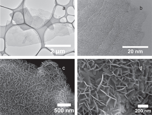
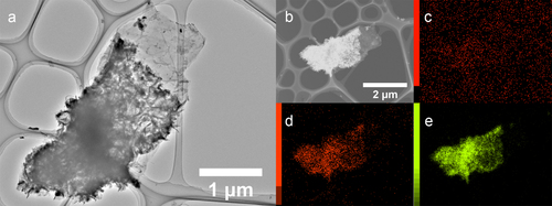
Figure (a) shows graphene with a Co(OH)2 coating. We can observe that the Co(OH)2 nano-sheets are still on the surface of the graphene after sonication was applied in the preparation of the TEM sample, indicating that we can make a robust composite by in situ deposition. An elemental mapping was carried out on the same piece of sample. Although the carbon mapping was not helpful because of the amorphous carbon film on the copper grid (figure (c)), the Co(OH)2 coating is well revealed by the elemental mapping of oxygen and cobalt, which is shown in figures (d) and (e), respectively.
Figure 3 TEM image and elemental mapping of Co(OH)2-coated graphene. (a) TEM image of Co(OH)2-coated few-layer graphene. (b) Dark-field image of the same Co(OH)2-coated graphene piece combined with maps of carbon (c), oxygen (d) and cobalt (e).
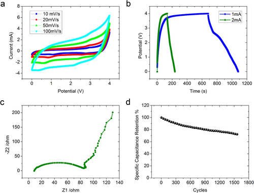
The capacitance of an electrode is sensitive to the cell configuration used for the electrochemical measurement, and it is always significantly higher when using a three-electrode system [Citation31]. A two-electrode test cell was therefore used in this work because it can provide the most accurate measurement of the material performance of the supercapacitor [Citation32]. We used an ionic liquid electrolyte EMI-TFSI for a higher operating (charging/discharging) voltage. Figure (a) shows the CV curves of graphene–CNT supercapacitor in EMI-TFSI at different scan rates ranging from 10 to 200 mV s−1. The symmetric and hysteretic CV loops indicate excellent charge propagation in the electrodes. As we know, the shape of the CV loop of an ideal capacitor should be rectangular if the contact resistance is small. A larger resistance distorts the loop and results in a narrower loop with an oblique angle. Figure (b) shows the galvanostatic charge/discharge curves of the composite electrode at charging currents of 1 and 2 mA. Both charging curves show a relatively flattened plateau after 3.7 V. This is due to the reactions with the functional groups present on the electrode when it was charged to such a high voltage. We obtained a specific capacitance of 310 F g−1 at 1 mA (1 A g−1) and 100 F g−1 at 2 mA (2 A g−1) with a maximum energy density of 172 Wh kg−1. Figure (c) is the Nyquist plot of impedance collected in the frequency range between 100 kHz and 0.01 Hz for the graphene–CNT–Co(OH)2 composite. As expected from a supercapacitor at low frequency, the imaginary part increases sharply and a nearly vertical line is observed, indicating a predominantly capacitive behavior in action. As the frequency increases, the influence of the electrode porosities is observed as indicated by a constant phase element typified by the Warburg curve [Citation33]. The EIS curve shown in figure (c) is nearly linear in the low-frequency region, and has a semi-circular shape in the high-frequency region, from which the interfacial leakage resistance, RF, due to overcharge or faradaic redox reactions caused by impurities or functional groups, can be deduced with a simplistic model. The smaller the RF, the greater the kinetic reversibility of the faradaic reactions. In a practical supercapacitor, to a good approximation, it can be regarded as being composed of a non-faradaic current for electrochemical double-layer charging in parallel with some faradaic current component through RF. We can learn that the graphene–CNT–Co(OH)2 composite has a small charge-transfer resistance. The equivalent series resistance (ESR) of 8.2 Ω for the supercapacitor with the graphene–CNT and the graphene–CNT–Co(OH)2 electrodes was obtained from the Z1-intercept. The maximum power density pmax was calculated by pmax = Vmax 2 /(4mRESR ), where RESR is the equivalent series resistance, m is the total weight of the two electrodes and Vmax is the maximum charging voltage. Using Vmax = 4 V for the EMI-TFSI electrolyte, the obtained maximum power density for the graphene–CNT and graphene–CNT–Co(OH)2 supercapacitor was 198 kW kg−1. Figure (d) shows the cycling performance of the asymmetric supercapacitor with a Co(OH)2 coating of 1 mg cm−2 at a charging current density of 2 A g−1. The capacitance dropped by 30% after 1500 cycles, showing reasonable performance for an asymmetric supercapacitor, where pseudocapacitance must also have contributed to the device performance due to the coated Co(OH)2 from the redox reaction Co(OH)2 + TFSI− → CoOOH + HTFSI + e−.
Figure 4 Electrochemical properties of Co(OH)2 coated graphene–CNT composite. (a) CV curves of graphene–CNT–Co(OH)2 composite at different scan rates ranging from 10 to 100 mV s−1 in EMI-TFSI electrolyte. (b) Galvanostatic charge/discharge curves of the composite at charging currents of 1 and 2 mA. (c) Nyquist plot of EIS data of graphene–CNT–Co(OH)2 composite electrode. (d) Cycling performance of graphene–CNT–Co(OH)2 composite at charging density of 2 A g−1.
Conclusions
We have fabricated graphene–CNT and graphene–CNT–Co(OH)2 electrodes and assembled them in asymmetric supercapacitors. The single-walled CNTs act as a conductive spacer as well as a conductive binder in this composite structure. A high energy density of 172 Wh kg−1 and a maximum power density of 198 kW kg−1 were obtained.
Acknowledgments
This work was supported by JSPS Grants-in-Aid for Scientific Research numbers 19310081 and 22310074, JST ALCA Program and the Nanotechnology Network Project of the Ministry of Education, Culture, Sports, Science and Technology (MEXT), Japan.
Related Research Data
References
- SimonPGogotsiY 2008Materials for electrochemical capacitors Nature Mater. 7 845 854 845–54 10.1038/nmat2297
- MillerJ RSimonP 2008 Materials science—electrochemical capacitors for energy management Science 321 651 652 651–2 10.1126/science.1158736
- ZhangL LZhaoX S 2009Carbon-based materials as supercapacitor electrodes Chem. Soc. Rev. 38 2520 2531 2520–31 10.1039/b813846j
- FrackowiakEBeguinF 2001Carbon materials for the electrochemical storage of energy in capacitors Carbon 39 937 950 937–50 10.1016/S0008-6223(00)00183-4
- FrackowiakEBeguinF 2002Electrochemical storage of energy in carbon nanotubes and nanostructured carbons Carbon 40 1775 1787 1775–87 10.1016/S0008-6223(02)00045-3
- FutabaD NHataKYamadaTHiraokaTHayamizuYKakudateYTanaikeOHatoriHYumuraMIijimaS 2006Shape-engineerable and highly densely packed single-walled carbon nanotubes and their application as super-capacitor electrodes Nature Mater. 5 987 994 987–94 10.1038/nmat1782
- WangYShiZ QHuangYMaY FWangC YChenM MChenY S 2009Supercapacitor devices based on graphene materials J. Phys. Chem. C 113 13103 13107 13103–07 10.1021/jp902214f
- StollerM DParkS JZhuY WAnJ HRuoffR S 2008Graphene-based ultracapacitors Nano Lett. 8 3498 3502 3498–502 10.1021/nl802558y
- WangD WLiFZhaoJ PRenW CChenZ GTanJWuZ SGentleILuG QChengH M 2009Fabrication of graphene/polyaniline composite paper via in situ anodic electropolymerization for high-performance flexible electrode ACS Nano 3 1745 1752 1745–52 10.1021/nn900297m
- PandolfoA GHollenkampA F 2006Carbon properties and their role in supercapacitors J. Power Sources 157 11 27 11–27 10.1016/j.jpowsour.2006.02.065
- ParkSRuoffR S 2009Chemical methods for the production of graphenes Nature Nanotechnol. 4 217 224 217–24 10.1038/nnano.2009.58
- YanJWeiTShaoBFanZQianWZhangMWeiF 2010Preparation of a graphene nanosheet/polyaniline composite with high specific capacitance Carbon 48 487 493 487–93 10.1016/j.carbon.2009.09.066
- ChengQTangJMaJZhangHShinyaNQinL-C 2011Graphene and carbon nanotube composite electrodes for supercapacitors with ultra-high energy density Phys. Chem. Chem. Phys. 13 17615 17624 17615–24 10.1039/c1cp21910c
- FischerA EPettigrewK ARolisonD RStroudR MLongJ W 2007Incorporation of homogeneous, nanoscale MnO2 within ultraporous carbon structures via self-limiting electroless deposition: implications for electrochemical capacitors Nano Lett. 7 281 286 281–6 10.1021/nl062263i
- ChangJ KLeeM TTsaiW TDengM JChengH FSunI W 2009Pseudocapacitive mechanism of manganese oxide in 1-ethyl-3-methytimidazolium thiocyanate ionic liquid electrolyte studied using x-ray photoelectron spectroscopy Langmuir 25 11955 11960 11955–60 10.1021/la9012119
- BabakhaniBIveyD G 2010Anodic deposition of manganese oxide electrodes with rod-like structures for application as electrochemical capacitors J. Power Sources 195 2110 2117 2110–7 10.1016/j.jpowsour.2009.10.045
- ChengQTangJMaJZhangHShinyaNQinL-C 2011Graphene and nanostructured MnO2 composite electrodes for supercapacitors Carbon 49 2917 2925 2917–25 10.1016/j.carbon.2011.02.068
- ConwayB E 1991Transition from supercapacitor to battery behavior in electrochemical energy-storage J. Electrochem. Soc. 138 1539 1548 1539–48 10.1149/1.2085829
- LongJ WSwiderK EMerzbacherC LRolisonD R 1999Voltammetric characterization of ruthenium oxide-based aerogels and other RuO2 solids: the nature of capacitance in nanostructured materials Langmuir 15 780 785 780–5 10.1021/la980785a
- YanJFanZ JWeiTQianW ZZhangM LWeiF 2010Fast and reversible surface redox reaction of graphene–MnO2 composites as supercapacitor electrodes Carbon 48 3825 3833 3825–33 10.1016/j.carbon.2010.06.047
- LiG RFengZ POuY NWuDFuRTongY X 2010Mesoporous MnO2/carbon aerogel composites as promising electrode materials for high-performance supercapacitors Langmuir 26 2209 2213 2209–13 10.1021/la903947c
- JayashreeR SKamathP V 1999Electrochemical synthesis of alpha-cobalt hydroxide J. Mater. Chem. 9 961 963 961–963 10.1039/a807000h
- LiangY YCaoLKongL PLiH L 2004Synthesis of Co(OH)2/USY composite and its application for electrochemical supercapacitors J. Power Sources 136 197 200 197–200 10.1016/j.jpowsour.2004.05.009
- TungV CAllenM JYangYKanerR B 2009High-throughput solution processing of large-scale graphene Nature Nanotechnol. 4 25 29 25–9 10.1038/nnano.2008.329
- StankovichSDikinD ADommettG H BKohlhaasK MZimneyE JStachE APinerR DNguyenS TRuoffR S 2006Graphene-based composite materials Nature 442 282 286 282–6 10.1038/nature04969
- GeimA KKimP 2008Carbon wonderland Sci. Am. 298 90 97 90–7 10.1038/scientificamerican0408-90
- BecerrilH AMaoJLiuZStoltenbergR MBaoZChenY 2008Evaluation of solution-processed reduced graphene oxide films as transparent conductors ACS Nano 2 463 470 463–70 10.1021/nn700375n
- HummersW SOffemanR E 1958Preparation of graphitic oxide J. Am. Chem. Soc. 80 1339 10.1021/ja01539a017
- ChengQTangJMaJZhangHShinyaNQinL-C 2011Polyaniline-coated electro-etched carbon fiber cloth electrodes for supercapacitors J. Phys. Chem. C 115 23584 23590 23584–90 10.1021/jp203852p
- AnYZuoPChengXLiaoLYinG 2011Preparation and properties of ionic-liquid mixed solutions as a safety electrolyte for lithium ion batteries Int. J. Electrochem. Sci. 6 2398 2410 2398–410
- FrackowiakEKhomenkoVJurewiczKLotaKBeguinF 2006Supercapacitors based on conducting polymers/nanotubes composites J. Power Sources 153 413 418 413–8 10.1016/j.jpowsour.2005.05.030
- KhomenkoVFrackowiakEBeguinF 2005Determination of the specific capacitance of conducting polymer/nanotubes composite electrodes using different cell configurations Electrochim. Acta 50 2499 2506 2499–506 10.1016/j.electacta.2004.10.078
- PortetCTabernaP LSimonPLaberty-RobertC 2004Modification of Al current collector surface by sol–gel deposit for carbon–carbon supercapacitor applications Electrochim. Acta 49 905 912 905–12 10.1016/j.electacta.2003.09.043