
Abstract
To investigate the role of preexisting twin boundaries in magnesium alloys during the deformation process, a large number of {10-12} tensile twins were introduced by a radial compression at room temperature before hot compressive tests with both low and high strain rates. Unlike the stable twins in Cu-based alloys with low stacking fault energies, {10-12} twins in Mg alloy are extremely unstable or easy to detwin through {10-12}-{10-12} re-twinning. As a result, non-lenticular residual twins and twin traces with misorientation of 5°–7° were present, as confirmed by electron backscatter diffraction. The extreme instability of the twins during compression indicates that both twin and detwinning require extremely low resolved shear stresses under our experimental conditions.
Introduction
Twinning and detwinning in Mg alloys during cyclic deformation processes is an important subject, which is related to either the deformation behavior [Citation1–Citation5] or anelastic recovery behavior of Mg alloys [Citation6, Citation7]. Lou et al [Citation8] revealed that twinning occurs during compression of AZ31B Mg alloy; detwinning occurs under the subsequent tension when the compression is relaxed. Caceres et al [Citation6] analyzed the twinning–detwinning behavior of magnesium alloys by carrying out cyclic tensile tests. The results indicated that hysteresis curves of Mg alloys are closely related to the cyclic motions of the twin boundary during the cyclic process. In a model proposed by Li and Enoki [Citation9–Citation12], detwinning of Mg alloys during unloading was ascribed to the internal stress arising from the resistance of the matrix to macroscopic changes in the twinned volume. When the external stress was withdrawn, internal stress could result, at least partly, in the opposite effect, namely, deformation by detwinning. In other words, detwinning of Mg alloy can be treated as a twinning process with a reverse twin variant. These results also imply that twins in Mg alloys are not stable because of the extremely low resolved shear stress for detwinning. In contrast, the result obtained by Lu et al [Citation13] indicated that pure copper samples with a high density of nanoscale Σ3 twin boundaries showed substantially higher tensile stresses due to the effective blockage of dislocation motion by numerous coherent twin boundaries. This is consistent with the results of Miura et al [Citation14] where in both pure Cu and Cu–Al alloys, with average grain sizes from 8.4 to 176.0 μm, it was found that twin boundaries are almost equivalent to grain boundaries in terms of their effect on the strength, because many dislocations pile up against the stable twin boundaries during deformation. It should be noted that unlike the stable twins in Cu alloy due to its extremely low stacking fault energy, the twins in Mg alloy, especially those formed by {10-12} twinning, are extremely unstable, which can easily shrink or grow even under an extremely low stress [Citation6]. Nevertheless, no systematic research has ever been carried out from a microscopic viewpoint on the detwinning behavior of Mg alloy.
Hence, in the present research, in order to evaluate the role of a preexisting twinning interface in the subsequent deformation process, the detwinning activity during hot compression was investigated in twin-containing AZ31B alloy using electron backscattering diffraction (EBSD) analysis. The results are very helpful in explaining the role of the twin boundary during deformation for not only Mg alloys but also other metallic materials with the hexagonal close packed crystalline structure.
Experimental details
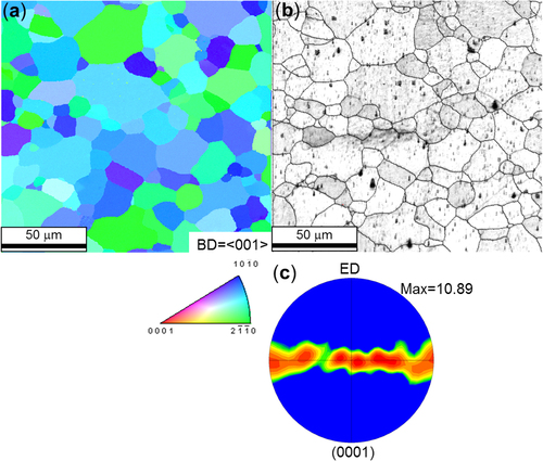
Cylindrical samples of AZ31 alloy (8 mm in diameter and 12 mm in height) were cut from an as-received hot-extruded rod (8 mm diameter, Osaka Fuji Corporation) followed by an annealing. The initial microstructure, shown by the inverse pole figure (IPF) and image quality (IQ) maps in figure , is free of twinning. It reveals a mean grain size of approximately 25 μm with a strong basal texture, in which most of the basal planes are aligned parallel to the extrusion direction (ED) (figure (c)).
Figure 1 (a) IPF map plotted along the ED of the sample, (b) the corresponding IQ map, and (c) {0001} pole figure of the initial microstructure of the as-extruded AZ31 alloy obtained from an area of 540 × 540 μm with a step size of 0.5 μm at the center of the sample. In (b) black lines indicate the high-angle grain boundary, and no twin boundary was identified.
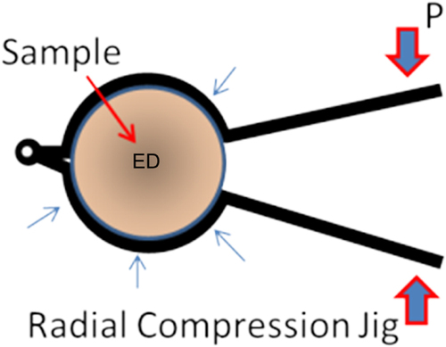
Before the hot compressive test, the sample was pre-stressed at room temperature by application of radial stress (about 50 MPa) normal to the lateral surface of the sample using custom-designed equipment (figure ). Prior to compression, annealing on all samples was carried out at 250 °C for 5 min in order to remove the dislocations induced by the radial compression without destroying the twinning density. Hot compressive tests at 250 °C along the ED were carried out on both the radially compressed and as-received samples in a vacuum using a computer-aided Thermecmaster-Z hot-forging simulator with a strain rate of 10−3 s−1. In these tests, it was confirmed that no further deformation twinning occurs during the deformation process; thus the activity of the preexisting twins during the subsequent deformation process can easily be clarified. A strain rate of 10 s−1 was also selected for comparison. The specimens were heated to the target temperature at a rate of 5 °C s−1 by high-frequency induction. As soon as the samples were compressed to the final strain level, they were quenched to room temperature with high-pressure He (0.4 MPa) to freeze the high-temperature microstructure.
Figure 2 Schematic of the radial compression jig used in this study. ED marks the extrusion direction.
Microstructural analysis of the centers of the compressed samples was carried out using an EBSD instrument equipped with data acquisition software (TSL-OIM 5.0). The textures of the samples were evaluated by plotting the pole figures, where all samples were scanned by the EBSD equipment over a fixed area (540 × 540 μm) with a step size of 0.5 μm.
Results and discussion
Radially compressed microstructure
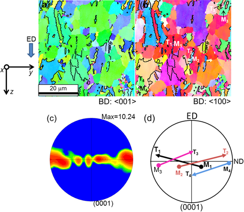
The microstructure after radial compression at room temperature is illustrated in figure by IPF maps plotted for observation directions both along the ED and perpendicular to the ED. A significant microstructure refinement due to the formation of twin boundaries was observed: the mean grain size of the sample including twin boundaries was estimated to be approximately 12 μm, which is half that of the as-received sample. In the matrix grains, many near-lenticular twins are observed dispersed either in the interiors of the grains or along the grain boundaries, as indicated by black lines. They are all identified as {10-12} <10-11> tensile twins by EBSD. In contrast to the twinning with group rotations of the c-axis into the ED during uniaxial compression along the ED [Citation12], under radial compression the twinning is observed to occur with rotations of the c-axis almost within the plane perpendicular to ED. As a result, no noticeable variation in the overall texture of the sample is observed, as indicated by the (0001) pole figure in figure (c). For a more detailed analysis of these special twins, four numbered grains M 1, M 2, M 3, and M 4; their corresponding twins T 1, T 2, T 3, and T 4 were selected, as indicated in figure (b). The orientations of the c-axes before and after twinning are indicated in figure (d) by the (0001) pole figure. The twinning variant was chosen so that the orientation of the c-axis was mostly within ±30° of the equator in the pole figure.
Figure 3 (a), (b) IPF maps plotted along the ED and direction perpendicular to the ED of the sample after application of a radial stress of about 50 MPa at room temperature. (c) Corresponding {0001} pole figure. (d) (0001) pole figure of four numbered grains and their corresponding twins in (b) indicated by arrows from the starting and ending directions of the c-axis during the twinning process.
Stress–strain curves
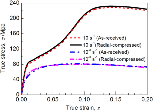
For samples with and without radial compression, the true stress–true strain (σ–∊) curves obtained at 250 °C and strain rates of 10−3 s−1 and 10 s−1 are presented in figure . It should be noted that after a large number of {10-12} twin boundaries was introduced, the radially compressed sample did not demonstrate significant increase in stress as reported by both Xin et al [Citation15] and Furui et al [Citation16], in contrast to the as-received sample. As found in most research on Mg alloys without prior radial compression [Citation17–Citation20], the flow curves obtained at a strain rate of 10 s−1 exhibit yield points at around 62 MPa for both samples, followed by strong work hardening reflected as a concave shape. Similarly, the flow curves of the samples obtained at a low strain rate demonstrate comparable stress levels: after both samples yield at a lower point (about 35 MPa), clear work softening is observed.
Figure 4 Stress–strain curves of the as-extruded sample and radially compressed sample obtained at 250 °C and strain rates of 20 s−1 and 0.001 s−1, respectively.
Microstructure evolution
During compression at 10 s−1, the twin that occurred during the prior radial compression can no longer be observed, even after the strain reaches 0.02, as shown in figure (a). In contrast, a fresh twin with a group rotation of c-axes into the ED occurs extensively. As a result, a significant increase in the maximum value of the {0001} plane density along the ED in the pole figure occurred as shown in figure (b).
Figure 5 (a) IPF map and (b) corresponding (0001) pole figure of the radially compressed sample after hot compression at 250 °C and 10 s−1 to a true strain of 0.02.
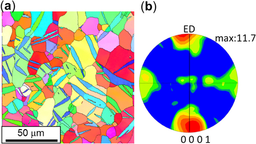
Figure shows IPF maps illustrating the microstructures of radially compressed samples subsequently subjected to compression at 10−3 s−1 along the ED to strains of 0.02, 0.04, and 0.08. With increasing strain, the twins formed during the radial compression disappear gradually, indicating the occurrence of detwinning similar to that occurring at the higher strain rate, but with a much lower rate. No dynamic recrystallization is observed at these strain levels; in addition the texture did not vary significantly, which is quite similar to those of both the as-received (figure ) and the radially compressed samples, as shown in figures (a)–(c), except for the slightly decreased {0001} plane density. The corresponding misorientation angle distributions in the range of 2° to 100° at these strains are plotted in figure . Two separate boundary misorientation peaks at angles of 5°–7° and 86°–88° were observed. It is also clear from the radial axis distributions of the peak boundaries in the insets in figure that these peaks share a <2-1-10> rotation axis. In addition to the decrease in the intensity of the {10-12} twinning peak (86°–88°/<2-1-10>) with strain, a gradual increase in the fraction of 5°–7°/<2-1-10> low-angle boundaries (LABs) was clearly observed, implying that the twin boundaries were possibly replaced by these LABs after detwinning.
Figure 6 IPF maps of the radially compressed sample after hot compression at 250 °C and 10−3 s−1 to true strains of (a) 0.02, (b) 0.04, and (c) 0.08.
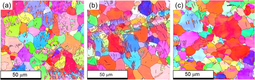
Figure 7 (0001) pole figures corresponding to the IPF maps of figure of the radially compressed sample after hot compression at 250 °C and 10−3 s−1 to true strains of (a) 0.02, (b) 0.04, and (c) 0.08.
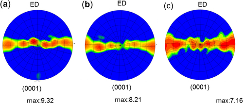
Figure 8 Misorientation angle distributions of the radially compressed sample after hot compression at 250 °C and 10−3 s−1 to true strains of 0.02, 0.04, and 0.08, in which two prominent peaks at 5°–7° and 86°–88° are clearly seen. These peaks share the same rotation axis, <2-1-10>, as shown by the rotation axis distributions of the boundaries of the peaks in the insets.
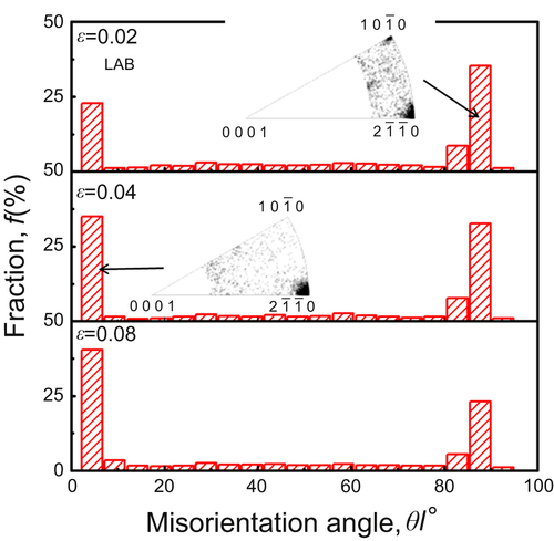
Figure shows the magnified microstructures after hot compression (10−3 s−2) to a true strain of 0.02 as IPF and IQ maps. Partial detwinning is observed clearly at this strain level. In contrast to the detwinning induced by reverse loading, which left residual lenticular twins without twinning traces, as observed by Caceres et al [Citation6] and Yasutomi and Enoki [Citation21], the detwinning behaves very inhomogeneously under the present conditions and seems to initiate not from the tips but in the interiors of preexisting twins. Therefore, the residual twins observed in the present research are much more irregular; distinct twin boundary traces are observed after detwinning, as indicated by the white lines in the IPF map (figure (a)) and the contrast in the IQ map (figure (b)). A large number of granular grains finer than 1 μm that are sporadically distributed along the twin traces or in the interior of the detwinned region are also observed to roughly follow the original twinning relationship with the detwinned area, but they finally disappear together with the residual twins at higher strain levels (figure (c)). From the abovementioned results, it is clear that the twin boundary is extremely unstable under the conditions investigated here and that detwinning tends to take place at a low strain level.
Figure 9 (a) IPF map in the plane perpendicular to the ED of the sample after hot compression at 250 °C and 10−3 s−1 to ∊ = 0.02, where the black and white lines represent the {10-12} twin boundary and LABs (5°–7°), respectively. (b) IQ map clearly showing the twin traces after detwinning, in which the red line represents the {10-12} twin boundary. (c) Point-to-point misorientation profiles along the straight line in (b), indicating that most of the twinning trace had misorientation angles of 5°–7°. (d) Misorientation angle distribution of (a), showing misorientation axis distributions with peaks at 5°–7° and 86°–88° that share the same rotation axis of <2-1-10>.
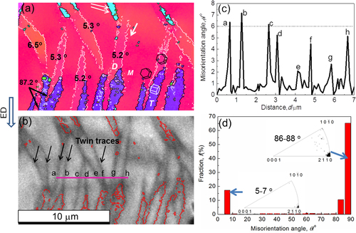
Typical twinning traces in figures (a), (b) are selected and numbered from a to h, and the resulting point-to-point misorientation profile across these traces indicates that most of the detwinning leads to LABs with misorientation angles of 5°–7° (figure (c)). To analyze these twinning traces in more detail, the misorientation angle distributions of the boundaries in figure (a), which dominantly include both the residual twin boundaries and the twinning trace boundaries, were plotted in figure (d). The rotation axis distributions of the prominent peaks are also included. Like those in figure , the results indicate two separate boundary misorientation peaks in the ranges of 5°–7° and 86°–88°, with their overall number fraction above 95%. From the corresponding rotation axis distributions in figure (d), both of these peaks are observed to have the same rotation axis, <2-1-10>. On the basis of these results, it is confirmed that the detwinning occurring under the conditions investigated here proceeds through formation of {10-12}-{10-12} re-twin boundaries [Citation22–Citation24], leaving twinning traces with misorientation angles of 5°–7°.
Detwinning
Both twinning during radial compression and detwinning in the subsequent hot compression are schematically described in figure . In figure (a), position (1) denotes the orientation of the initial parent grain in the as-received sample, with its c-axis roughly normal to the ED. When {10-12} twinning occurs during the radial compression, reorientation by approximately 87° occurs within the plane perpendicular to the ED of the extruded sample from (1) to (2), because this twinning variant has the highest Schmid factor. During the subsequent compression along the ED, there are two possible twinning variants for detwinning: reorientation of the c-axis forward by another 87° following (2) * (3), which is the same twinning variant that occurs during radial compression, and reorientation in the reverse direction to the original position following (2) * (1). Detwinning through the (2) * (1) route will give rise to a complete disappearance of the twin boundary or no twinning trace, like that during reverse loading [Citation21, Citation25]. In contrast, detwinning through the (2) * (3) route actually proceeds through {10-12}-{10-12} re-twinning which will be accompanied by a transition of the twin boundaries (87°) into LABs with misorientation angles of about 6° (figure ).
Figure 10 (a) Two possible ways the c-axis can rotate during detwinning in a double twinning process in the interior of an existing twin. (b) Schematic figure showing the detwinning traces and a typical geometry of the residual twin at elevated temperature. (c)–(e) Schematic diagrams showing the grain rotations due to twinning during the radial compression (from (c) to (d)) and the subsequent detwinning process (from (d) to (e)) with the same twinning variant. In planes (c) and (d) the shear direction was indicated by a red solid arrow, and both the radial compression and the subsequent hot compression process were all indicated by open arrows; the rotation axis of the lattice during the twinning process is indicated by a dash-dotted line.
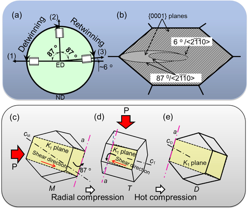
Three different regions were selected and indicated in figure (a) by characters M, T, and D to denote the parent grain, the twinned region formed under the radial compression, and the detwinned region, respectively. For the parent grain M, as shown schematically in figures (c) and (d), the chosen twinning variant exhibits shear along the red arrow around the a-axis with a rotation of 87° to produce the (10–12)<10-11> twin (T) during the radial compression. In the subsequent compression along the ED, detwinning proceeds through double twinning in the interior of twin T with exactly the same twinning variant, resulting in twinning traces with misorientation angles of 5°–7° with respect to the matrix M (the angle between c M and c D ) after the double rotation of the c-axis around the same axis a.
The Schmid factors and the corresponding critical resolved shear stresses (CRSSs) for various deformation modes in the interior of the parent grain M and in the interior of twin T were calculated based on the EBSD measurements as tabulated in table . The Schmid factors of the non-basal slips in both M and T are above 0.45, much higher than those of the basal slip systems (0.274 for M and 0.099 for T). For the basal slip system, the Schmid factor in T decreased to close to 0.1 from the 0.27 Schmid factor in M because of reorientation of the grain by twinning, implying that the basal slip activity in T becomes lower while the non-basal slips activity is increased accordingly. The non-basal slip activity is also higher because of the substantially decreased CRSS of non-basal slip systems at elevated temperature [Citation26–Citation28]. For detwinning along the (2) * (1) route with the (−1012)<10-11> twinning variant or the (2) * (3) route with the reverse twinning variant (−1012)/<-101-1>, as indicated in figure , both Schmid factors are extremely close to 0 (table ). The resolved stresses for detwinning at this strain level (2%) through the (2) * (1) and (2) * (3) double twinning processes are calculated to be about 1.55 MPa and −1.55 MPa, respectively, implying an extremely low possibility of detwinning activated directly by the external stress at such a low stress level, especially for route (2) * (3).
Table 1 Schmidt factors of several deformation modes calculated in the M, T, and D regions marked in figure (a) and the corresponding critical resolved shear stresses.
Figure 11 Relation between the loading direction and the detwinning variants for both the (2) to (1) and (2) to (3) routes.
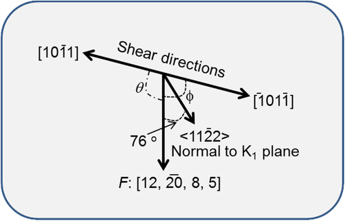
This is in conflict with most previously reported results [Citation24–Citation27], where twinning activity was mostly dominated by the Schmid factor. In contrast to the low activity of non-basal slip systems at room temperature, at 250 °C non-basal slip systems are considered to be strongly activated to accommodate the deformation due to the drastically decreased CRSS at higher temperature [Citation29–Citation32] (table ). It is thus speculated that the activation of a large amount of non-basal slips in the interior of the twinning region possibly alters the stress field inside the twinning region, with the result that activation of (−1012)/<-101-1> double twinning becomes possible. This is also consistent with our present results, where at a low strain level a residual twinned granular structure remained along the preexisting twin boundaries after hot compression, as indicated by double arrows in figure (a). Therefore, at a higher strain rate, detwinning occurred at a much smaller strain (figure ) than at the lower strain rate, possibly because of the higher stress applied to the sample. In particular, the shear stress for detwinning indirectly applied by the activation of non-basal slips in the interior of the twinning greatly promoted the detwinning.
Conclusions
In order to investigate the role of preexisting twin boundaries in magnesium alloys in the deformation process, hot compressive tests were conducted with both low and high strain rates on samples in which a large number of {10-12} tensile twins were introduced by radial compression at room temperature before the hot compression. The results are summarized as follows:
| (1) | The {10-12} twins in Mg alloy are extremely unstable; detwinning through {10-12}-{10-12} re-twinning was confirmed by electron backscatter diffraction. In this double twinning process, the same twinning variant occurs as had proceeded to form the preexisting twin, resulting in non-lenticular residual twins and twinning traces with a misorientation of 5°–7°. | ||||
| (2) | Both twinning growth and detwinning require extremely low resolved shear stress; for a Mg alloy with a large grain size, strengthening by introducing twin boundaries to refine the grain size is not as effective as reported before. | ||||
Acknowledgements
This research was supported by a Grant-in-Aid for Young Scientists B (24760591) from the Japan Society for the Promotion of Science.
References
- GharghouriM AWeatherlyG CEmbury J DRoot J 1999 Phil. Mag. A 79 1671 1695 1671–95 10.1080/01418619908210386
- BrownD WAgnewSAbelnS PBlumenthalW RBourkeM A MMatayaM CToméC NVogelS C 2005 The role of texture, temperature and strain rate in the activity of deformation twinning Icotom 14: Textures of Materials Van HouttePKestensL Zurich Trans Tech 1037
- WangY NHuangJ C 2007 Acta Mater. 55 897 905 897–905 10.1016/j.actamat.2006.09.010
- BrownD WJainAAgnewSClausenB 2007 Mater. Sci. Forum 539–543 3407 3414 3407–14 10.4028/www.scientific.net/MSF.539-543
- BeyerleinI JWangJKangKZhengS JMaraN A 2013 Mater. Res. Lett. 1–2 89 95 89–95 10.1080/21663831.2013.782074
- CaceresC HSumitomoTVeidtM 2003 Acta Mater. 51 6211 6218 6211–8 10.1016/S1359-6454(03)00444-0
- WuLJainABrownD WStoicaG MAgnewS RClausenBFieldenD ELiawP K 2008 Acta Mater. 56 688 695 688–95 10.1016/j.actamat.2007.10.030
- LouX YLiMBogerR KAgnewSWagonerR H 2007 Int. J. Plast. 23 44 86 44–86 10.1016/j.ijplas.2006.03.005
- LiY PEnokiM 2008 Mater. Trans. 49 1800 1805 1800–5 10.2320/matertrans.MC200705
- LiY PEnokiM 2007 Mater. Trans. 48 2343 2348 2343–8 10.2320/matertrans.MAW200720
- LiY PEnokiM 2011 J. Mater. Res. 26 3098 3105 3098–105 10.1557/jmr.2011.369
- LiY PWuSBianHTangNLiuBKoizumiYChibaA 2013 Scr. Mater. 68 171 174 171–4 10.1016/j.scriptamat.2012.10.007
- LuLShenYChenXQianLLuK 2004 Science 304 422 426 422–6 10.1126/science.1092905
- MiuraSOnoNNishimuraY 2008 J. Soc. Mater. Sci. Japan 57 921 928 921–8 10.2472/jsms.57.921
- XinYWangMZengZNieMLiuQ 2012 Scr. Mater. 66 25 28 25–8 10.1016/j.scriptamat.2011.09.033
- FuruiMMoritaTAidaTAnadaH 2010 Microstructure evolution of AZ31B magnesium alloy pre-strained by torsion working during warm compressive deformation 8th Int. Conf. on Magnesium Alloys and their Applications 326 330 326–30
- JiangLJonasJ JLuoA ASachdevA KGodetS 2007 Mater. Sci. Eng. A 445–446 302 309 302–9 10.1016/j.msea.2006.09.069
- WanGWuB LZhangY DShaG YEslingC 2010 Mater. Sci. Eng. A 527 2915 2924 2915–24 10.1016/j.msea.2010.01.023
- JiangLJonasJ JLuoA ASachdevA KGodetS 2007 Acta Mater. 55 3899 3910 3899–910 10.1016/j.actamat.2007.03.006
- KnezevicMLevinsonAHarrisRMishraR KDohertyR DKalidindiS R 2010 Acta Mater. 58 6230 6242 6230–42 10.1016/j.actamat.2010.07.041
- YasutomiTEnokiM 2012 Mater. Trans. 53 1611 1616 1611–6 10.2320/matertrans.MAW201218
- NaveM DBarnettM R 2004 Scr. Mater. 51 881 885 881–5 10.1016/j.scriptamat.2004.07.002
- ChoiS HShinE JSeongB S 2007 Acta Mater. 55 4181 4192 4181–92 10.1016/j.actamat.2007.03.015
- ChristianJ WMahajanS 1995 Prog. Mater. Sci. 39 1 165 1–165 10.1016/0079-6425(94)00007-7
- MannG ESumitomoTCaceresC HGriffithsJ R 2007 Mater. Sci. Eng. A 456A 138 146 138–46 10.1016/j.msea.2006.11.160
- HongS GParkS HLeeC S 2010 Acta Mater. 58 5873 5885 5873–85 10.1016/j.actamat.2010.07.002
- YoshidaYCisarLKamadoSKojimaY 2003 Mater. Trans. 44 468 475 468–75 10.2320/matertrans.44.468
- AkhtarATeghtsoonianE 1969 Acta Metall. 17 1351 1356 1351–6 10.1016/0001-6160(69)90152-7
- HillR 1968 J. Mech. Phys. Solids 16 315 322 315–22 10.1016/0022-5096(68)90018-5
- ProustGTomeC NJainAAgnewS R 2009 Int. J. Plast. 25 861 880 861–80 10.1016/j.ijplas.2008.05.005
- KleinerSUggowitzerP J 2004 Mater. Sci. Eng. A 379 258 263 258–63 10.1016/j.msea.2004.02.020
- QuSZhouH 2010 Nanotechnology 21 1 3 1–3