
Abstract
The effects of acid treatment, vapor grown carbon fiber (VGCF) interlayer and the angle, i.e., 0° and 90°, between the rolling stripes of an aluminum (Al) plate and the fiber direction of glass fiber reinforced plastics (GFRP) on the mode II interlaminar mechanical properties of GFRP/Al laminates were investigated. The experimental results of an end notched flexure test demonstrate that the acid treatment and the proper addition of VGCF can effectively improve the critical load and mode II fracture toughness of GFRP/Al laminates. The specimens with acid treatment and 10 g m−2 VGCF addition possess the highest mode II fracture toughness, i.e., 269% and 385% increases in the 0° and 90° specimens, respectively compared to those corresponding pristine ones. Due to the induced anisotropy by the rolling stripes on the aluminum plate, the 90° specimens possess 15.3%–73.6% higher mode II fracture toughness compared to the 0° specimens. The improvement mechanisms were explored by the observation of crack propagation path and fracture surface with optical, laser scanning and scanning electron microscopies. Moreover, finite element analyses were carried out based on the cohesive zone model to verify the experimental fracture toughness and to predict the interface shear strength between the aluminum plates and GFRP laminates.
Introduction
Carbon or glass fiber reinforced plastics (GFRP)/metal laminate is a kind of hybrid composite, combining the advantages of metallic materials and fiber reinforced plastics (FRPs). Metallic materials are generally isotropic, have high strength and impact resistance while fiber reinforced matrix systems have excellent fatigue resistance. Therefore, the problems caused by the poor fatigue and corrosion resistance of metallic materials and the low bearing strength, impact resistance and reparability of carbon or glass fiber reinforced matrix plastics can be solved by combining them to a hybrid structure, namely fiber metal laminate (FML) [Citation1]. Since FMLs were invented, they have shown great potentials for various structural applications. For example, GFRP/aluminum (Al) laminates (commercial name: GLARE) have been applied to Airbus A380 as a skin material for the upper fuselage and the leading edges of the vertical and horizontal tail planes [Citation2]. However, the relatively weak bonding strength between metal and polymer makes the FMLs susceptible to crack initiation and propagation along the interfaces, which may lead to significant stiffness losses and premature failure, especially when subjected to compressive or shear loads. This interface debonding becomes more significant due to the residual thermal stress caused by thermal expansion mismatch of metal and FRPs, mainly in carbon fiber reinforced plastics (CFRPs)/metal laminates.
To enhance the bonding strength between the metal and polymer, various surface treatment methods [Citation3–Citation10] (e.g. abrasion, anodizing, excimer laser texturing, plasma-sprayed coating, etc) were employed. Zhang et al [Citation3] systematically studied the effects of various aluminum surface morphologies and roughness on the fracture resistance of the aluminum/epoxy interface. They found that the important parameter governing the fracture resistance of aluminum/epoxy interface is the microscopic roughness index rather than the nano-scale features of the aluminum surface. In contrast, Jang et al [Citation4] produced uniform nano-porous morphology using an anodizing method across the micro line pattern on the aluminum surface. Their results indicate that the CFRP/aluminum specimen with nano-scale morphology in the micro-scale line pattern possesses the highest maximum load bearing capacity compared with that of those with only the micro-scale line pattern. Alfano et al [Citation5] investigated the effect of laser irradiation on the Al/epoxy bonding strength by using laser irradiation to change the aluminum surface morphology. They concluded that the surface morphology change may promote mechanical interlocking, and leads to higher bonding strength. By employing Ar+ ion irradiation treatment on the surface of CFRP, Rhee et al [Citation6] demonstrated that the fracture toughness of ion beam-treated Al/CFRP composites was about 72% higher than that of the untreated case. They attributed this to the formation of hydrophilic functional bonds C = O (carbonyl group) and O–C = O (carboxyl group), which may lead to cohesive failure during interface delamination. Although these surface treatment methods can effectively enhance the mechanical properties of FMLs, they are generally expensive, time consuming and require special equipment, impeding their extensive applications.
Through-thickness reinforcements such as transverse stitching and z-pinning have been widely used to hold the plies together to improve the interlaminar strength of fiber reinforced laminated composites [Citation11–Citation14]. These methods prove to be effective in hindering delamination and its induced reduction of buckling loads in various laminates but may lead to lower in-plane mechanical performance. Moreover, they are obviously unsuitable for FMLs. Recently, a technique known as interleaving has attracted great interest [Citation15–Citation24]. For example Arai et al [Citation15] inserted carbon nanofibers, i.e., vapor grown carbon fiber (VGCF) and vapor grown carbon nanofiber between the CFRP prepreg sheets to improve the interlaminar fracture toughness. The mode I fracture toughness was enhanced by 50%, and the mode II fracture toughness was two to three times greater than conventional CFRP laminates. Using bucky paper as interleaves, which were fabricated by vacuum filtration of functionalized carbon nanofibers, into the interface between CFRP sub-laminates, Khan and Kim [Citation16] demonstrated 31% and 104% improvement in interlaminar shear strength and mode II fracture toughness, respectively. Lee et al [Citation17] introduced a carbon nanotube enhanced non-woven carbon tissue interleave to the interface of CFRPs. They reported that the mode I and mode II fracture toughnesses were enhanced by 35.3% and 246%, respectively. To date, there has been no report about using nanofillers toughened interleaves as the reinforcement for FMLs. In addition, it is not clear if the surface treatment methods on Al and the interleaving approach can be combined to improve the interlaminar fracture toughness of FMLs.
In this study, a simple but effective chemical treatment method, i.e., acid etching treatment was applied on the surfaces of aluminum alloy plates to increase their surface roughness. Moreover, a carbon nanofiller, i.e., VGCF was directly dispersed at the interface of GFRP and aluminum alloy plate to form a nanofiller interlayer. The mechanical property tests confirmed the significant increase of critical failure load and mode II fracture toughness. Moreover, the present toughing technique combined with acid etching treatment and nanofiller interlayer can be applied in the other FMLs, such as combinations of steel, titanium, or magnesium with carbon or glass fiber laminates.
Experiments
Fabrication of specimens
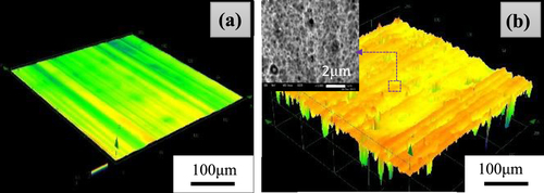
The materials used in fabrication of the GFRP/Al laminates are unidirectional GFRP prepregs (TOHO Tenax) and commercial aluminum alloy A2017 (TOHO Hitetsu-Kinzoku). VGCF (Showa Denko K K) was employed as the reinforcement in the interlayers. The detailed physical and mechanical properties of these materials are given in table . The manufacturing process of GFRP/Al laminates is schematically shown in figure . First, two pieces of aluminum alloy plates and a piece of [0°]3 GFRP laminate were stacked together through a lay-up process. Then, VGCF with three different contents were dispersed at the interface between the lower GFRP/Al laminate and the upper aluminum alloy layers during the lay-up process, where a simple fabrication technology with low production cost, i.e., powder method [Citation25], was employed. With this procedure, the VGCF/epoxy interlayers can be formed naturally by combining the VGCF powder and the epoxy resin leaked from the GFRP prepregs during the curing process. A polyamide film (Kapton, Toray) of 25 μm thickness was placed at one side of the laminate to create an initial crack. Then, the lay-up FMLs were wrapped by Kapton film and cured using a hot-press machine. The temperature and pressure used in the curing process are shown in figure . To promote adhesion between the GFRP laminates and the aluminum alloy plate, acid etching treatment was applied to the surface of aluminum alloy plates, in which the aluminum alloy plates were soaked in 1 mol L−1 nitric acid for 24 h to increase their surface roughness. Figure shows a confocal laser scanning microscopy (OLS4000, Olympus) image of the surface morphology of the aluminum plate before and after the acid etching. It is clear that a rough surface on the aluminum plate consisting of many small grooves and holes was created by the acid treatment. The average diameter is about 18 μm and the depth of the holes ranges from 2 μm to 5 μm. The sizes of the holes can be adjusted through changing the acid concentration and processing time to match the sizes of VGCF (table ). Note that there exist many small grooves or stripes on the surface of the supplied aluminum plate formed during the manufacturing process (figure ), which may lead to anisotropy in the GFRP/Al laminates. To examine the possible anisotropic effect on fracture toughness, the fiber direction was aligned in parallel or in perpendicular to the surface stripe direction. With different surface treatment procedures, area density of VGCF and fiber direction, 12 kinds of specimens were prepared. For simplicity, the specimens are referred to as Plain-0°, A-10-0°, V10-0°, A-V10-0°, A-V20-0°, A-V30-0° and Plain-90°, A-10-90°, V10-90°, A-V10-90°, A-V20-90°, A-V30-90° respectively, where ‘Plain’ denotes the specimen without any treatment, ‘A’ denotes the acid-treatment, ‘V’ denotes the VGCF addition, ‘10, 20 and 30’ indicate the area densities of VGCF (g m−2), and ‘0° and 90°’ represent the fiber direction, either in parallel or perpendicular to the stripe direction on the Al plates. For each type of specimen, three samples were prepared.
Table 1 Physical and mechanical properties of GFRP prepregs, A2017 and VGCF.
Figure 1 Schematic illustration of the specimen fabrication process.
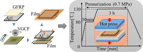
Figure 2 Surface morphology of the aluminum layers. (a) Before acid etching treatment; (b) after acid etching treatment.
End notched flexure test
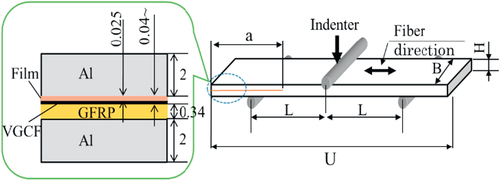
To evaluate the mode II interlaminar fracture toughness of GFRP/Al laminates, end notched flexure (ENF) tests were performed using a universal material testing machine (5982, Instron) at room temperature (25 °C) by referring to Japanese Industrial Standards (JIS) K7086 [Citation26]. Three specimens for each type of GFRP/Al laminates were prepared by cutting the molded plates using a wheel cutter. The dimensions of the specimen are schematically shown in figure . The compressive load was applied at the middle point of the specimen at a crosshead speed of 0.5 mm min−1. Based on the linear elastic fracture mechanics, the energy release rate, i.e., G, can be calculated through the following equation [Citation27],1 where P is load, a is crack length, B is specimen width and C represents compliance. For the ENF test, the compliance, C, is expressed [Citation28] as follows:
2 where L and h are half of the span length and half of the thickness of the specimen. δ and E
b are the deflection of the loading point and the effective bending modulus in the axial direction, respectively. Substituting equation (Equation2
2 ) into equation (Equation1
1 ), the mode II critical energy release rate, G
IIC, can be expressed as follows,
3 where P
C is the critical load at the initialization of crack growth. By substituting equation (Equation2
2 ) into equation (Equation3
3 ), the mode II fracture toughness can be finally evaluated as follows:
4 where δ
C is the critical deflection value at the loading point.
Figure 3 Specimen for ENF tests (length U = 140 mm; width B = 20 mm; height H = 4.34 mm; L = 50 mm; initial crack length a = 40 mm).
Results and discussion
mode II interlaminar fracture toughness
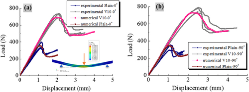
The typical load-crack opening displacement (COD) curves are plotted in figure , which show the comparison of representative specimens for each type of 0° and 90° GFRP/Al laminates. It can be observed that the load increases rapidly in an approximate linear way up to a peak load, then suddenly drops due to crack propagation. Note that for the specimens with different VGCF loadings, there are slight differences in the initial slopes of the load-COD curves, i.e., different Young’s moduli. All specimens with VGCF have a higher slope compared to the Plain specimens. The slope increases with VGCF added. The average critical loads P C of the three samples of different cases are shown in figure . It can be found that the critical load of V10, A-V0 specimens (both 0° and 90° specimens) increases rapidly compared to that of the Plain specimens, confirming the toughening effects of both acid etching treatment and addition of VGCF. For the acid treated specimens, the critical load further increases with the proper addition of VGCF. The highest critical load is observed in the specimen with 10 g m−2 VGCF. However, as VGCF content is above 10 g m−2, the critical load starts to decrease. The critical load of these specimens with 30 g m−2 VGCF is even lower than that of the specimen (A-V0) without VGCF addition. Note that the critical loads of 90° specimens with VGCF are higher than those of the 0° specimens. This implies that the angle between the stripe on the Al plates and the fiber direction has a great effect on the interlaminar mechanical properties. As shown in figure , the change of fracture toughness is similar to the critical load. The mode II fracture toughness increases in the order of Plain, V10, A-V0 to A-V10 specimens. However, when VGCF addition is over 10 g m−2, the fracture toughness starts to decrease for both 0° and 90° specimens.
Figure 4 Typical load-displacement curves for all kinds of (a) 0° GFRP/Al laminates; (b) 90° GFRP/Al laminates.
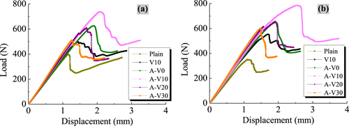
Figure 5 Critical loads of various GFRP/Al laminates.
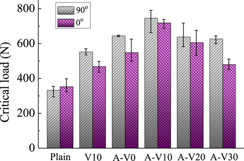
Figure 6 Fracture toughness at crack growth for various GFRP/Al laminates.
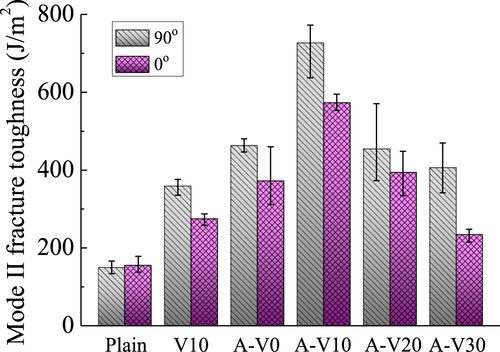
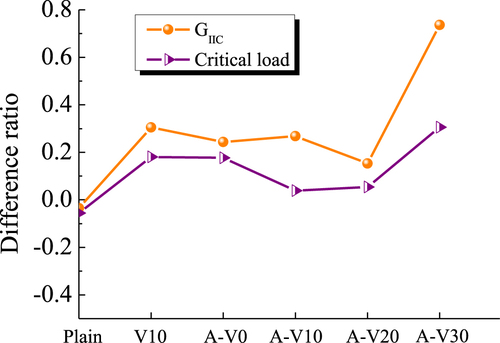
Figure shows the increasing ratios of critical load and fracture toughness of various treated specimens compared to those of the Plain specimens. It can be found that the A-V10-90° specimen has the highest critical load and fracture toughness, i.e., 124% and 385% higher than those of the Plain specimen. The data of the increasing ratio for the A-V10-0° specimen are 103% and 269%, respectively. Figure gives a comparison between the 90° specimens and the 0° specimens, i.e., difference ratio. It can be observed that the 90° specimens have 15.3%–73.6% higher fracture toughness and 3.86%–30.56% higher critical load than the 0° specimens. The most significant anisotropy appears in the case of A-V30, with 30 g m−2 VGCF addition. This indicates that the original surface condition of aluminum plates may have a great effect on the fracture toughness, especially for the specimens with high contents of VGCF.
Figure 7 Increasing ratios of critical load and fracture toughness for all kinds of specimens. (Increasing ratio: (PIncreased−PPlain)/P Plain, ‘P’ denotes GIIC or critical load, ‘Increased’ denotes samples of acid treatment or VGCF addition, and ‘Plain’ denotes pristine samples.)
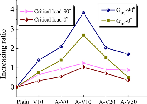
Figure 8 Difference ratios of critical load and fracture toughness of 90° specimens compared to 0° specimens. (Difference ratio: (P90°−P0°)/P0°, ‘P’ denotes G IIC or critical load, ‘90°’ denotes 90° samples, and ‘0°’ denotes 0° samples.)
Numerical simulation with the finite element method
As above, the mode II fracture toughness G IIC and critical load P C at crack initialization were estimated experimentally. The interlaminar shear strength, which relates to the critical load P C, should be investigated as well. Here, similar to [Citation25], we estimate the interlaminar shear strength by matching the numerical load-displacement curves to the experimental ones. The interlaminar tensile strength in numerical simulations was assumed to be equal to the shear strength, since, basically, this value has a minor impact on the numerical results in ENF tests. The experimental evidence for this assumption can be found in a previous work [Citation29], where it was observed that microcracks in the process zone were oriented to 45° relative to global crack propagation direction in the ENF tests of composite. Instead of experiments, two-dimensional finite element method (FEM) simulations of mode II crack propagation were carried out using ABAQUS to obtain interlaminar strength. Another purpose of the numerical simulations is to confirm the experimentally measured fracture toughness G IIC.
By employing a cohesive element COH3D8 of the ABAQUS code to model the VGCF interlayer, the crack initiation and propagation processes in ENF tests were simulated. The cohesive element size along the length direction of the beam was controlled to be smaller than 0.3 mm to overcome the strong numerical instabilities resuling from large cohesive elements [Citation30, Citation31]. A plane strain element CPE4I was used to model the GFRP sublaminates and aluminum plates. In order to examine the mesh convergence of the FEM model, two different square element sizes, i.e., 0.298 mm (the length of side) and 0.25 mm were chosen to build up the models. The simulation results of the two mesh sizes showed that the relative difference of peak load was within 2%, which indicates the present FEM model has a good convergence property and stability. Finally, the mesh size of 0.298 mm was used. The total number of elements in the model is 7020. Table gives the detailed material parameters of GFRP laminates and aluminum plates, where K is the initial stiffness of cohesive elements before crack propagation and N is the shear strength.
Table 2 Material properties of cohesive element.
The comparison between numerical simulation and experimental results is illustrated in figure . By matching the slope of the initial straight line and the peak load P C to the experimental load-COD curves with the lowest error, interlaminar shear strength, N, for the Plain and A-V10 specimens were determined as shown in table . In these computations, mode II toughness G IIC obtained from previous ENF experiments in table was directly used. Table shows that N is enhanced with acid treatment and addition of VGCF by 100% compared with that of the Plain specimens. It should be noted that the peak load is mainly dominated by G IIC and N only influences it slightly. Therefore, there is no obvious difference among numerically identified N for the 0° and 90° specimens in table . Good consistence between numerical and experimental results confirms the improvement of the mode II fracture toughness of GFRP/Al laminates by acid treatment and VGCF interlayer since the experimental values of G IIC were directly used in table . Conclusively, the above numerical simulations provide clear evidences for the improvement effect of acid treatment and VGCF interlayer on the interlaminar mechanical properties of GFRP/Al laminates, i.e., interlaminar shear strength and mode II fracture toughness.
Figure 9 Numerical and experimental load-displacement curves for (a) Plain-0° and V10-0° specimens; (b) Plain-90° and V10-90° specimens.
Crack path and fracture surface observations
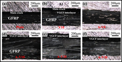
To uncover the relevant toughening mechanisms involved, the following experimental observations were conducted. For the sake of brevity, only 90° specimens were used. Figure shows the edge view optical microscopy pictures of the specimens during the ENF tests at the position of 10 mm from the crack initiation point. From figure (a), it can be found that the main crack propagates between the interface of Al and GFRP layers. This indicates the weak interface toughness for the Plain specimen. After VGCF addition, as shown in figure (b), the crack propagates at the interface of Al and the VGCF reinforced epoxy interlayer. As the bonding between the VGCF interlayer and Al may be stronger than that between the pure epoxy and Al, the fracture toughness of the V10 specimen is higher than that of the Plain specimen. When the acid etching process was applied on the surface of the aluminum plate (no VGCF addition), as described in figure (c), the crack propagates at the interface of Al and GFRP layers. However, there is remarkable glass fiber bridging during the crack propagation which indicates the good adhesion between the Al and GFRP layer caused by the acid etching treatment. As for the A-V10 specimen, it can be found from figure (d) that the crack propagates at the interface of the VGCF interlayer and GFRP layer. Because of the strong adhesion between the VGCF interlayer and GFRP layer, there is considerable glass fiber bridging and at some places, the crack deviated from the interface of the VGCF interlayer and GFRP layer into the VGCF interlayer or GFRP layer. Such fiber bridging and crack deviation usually result in the additional energy associated with the crack propagation. With increasing addition of VGCF, e.g., A-V20 and A-V30, as shown in figures (e) and (f), the crack almost propagates within the weak GFRP layers, and a lot of glass fibers are broken during the crack propagation process. This may indicate their relatively lower fracture toughness compared to that of the A-V10 specimen.
Figure 10 Crack propagation of all kinds of GFRP/Al laminates (a) Plain; (b) V10; (c) A-V0; (d) A-V10; (e) V20; (f) A-V30.
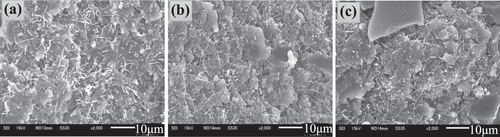
To further elucidate the mechanism, the fracture surfaces of all GFRP/Al laminates were observed with the laser scanning microscopy, as shown in figure . It can be found from figure (a), that there is only a little residual epoxy on the aluminum surface which implies more interfacial failures and weak adhesion for the Plain specimen. For the V10 and A-V0 specimens, as shown in figures (b) and (c), a lot of residual VGCF modified resin or pure epoxy resin exist on the aluminum surfaces which indicates the more cohesive failures within epoxy polymer occurring in these specimens. Therefore, the mode II fracture toughness of V10 and A-V0 specimens are higher than that of the Plain specimen. Meanwhile, figure (d) shows that almost the whole fractured surface of A-V10 specimen was covered by residual epoxy resin modified by VGCF. Moreover, there are some fractured glass fibers in the fractured surface of the A-V10 specimen which play a ‘bridging’ role to resist the crack propagation. Therefore, the fracture toughness of A-V10 is much higher than those of all other specimens. When VGCF loading is increased to 20 g m−2 and 30 g m−2, as shown in figures (e) and (f), the fracture surfaces were covered by glass fibers. This indicates that the fracture propagates into the weak GFRP layer for the A-V20 and A-V30 specimens, leading to the decreased fracture toughness. Figure shows the scanning electron microscopy (SEM) pictures of the fracture surface of A-V10, A-V20 and A-V30 specimens after ENF testing. Typical shear lips for the mode II deformation were observed on the fracture surface of all these specimens. However, figure shows more shear lips for A-V10 than A-V20 and A-V30 specimens. Moreover the shear lips for the A-V10 specimen are larger compared to those of A-V20 and A-V30 specimens. The more and larger shear lips indicate that the damage zone of A-V10 is much larger than those of the A-V20 and A-V30 specimens in the ENF testing process. Therefore, the more plastic deformation caused by the larger damage zone is the main reason for the higher fracture toughness of the A-V10 specimens. VGCF dispersion states are shown in figure . It can be found from figure that the VGCF is dispersed very well in the A-V10 specimen. However, when the density increases to 20 g m−2 and 30 g m−2, non-uniform dispersion and aggregation of VGCF can be observed. This may induce stress concentration and low bonding strength between VGCF and epoxy resin, which consequently results in the unstable crack propagation. Therefore, the mode II fracture toughness of A-V20 and A-V30 are lower than that of A-V10 specimen.
Figure 11 Fracture surface observation of all kinds of GFRP/Al laminates (a) Plain; (b) V10; (c) A-V0; (d) A-V10; (e) A-V20; (f) A-V30.
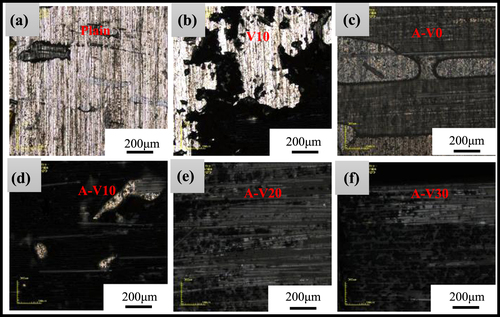
Figure 12 SEM images of fracture surface (a) A-V10; (b) A-V20; (c) A-V30.
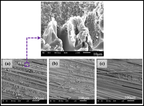
Figure 13 VGCF dispersion condition (a) A-V10; (b) A-V20; (c) A-V30.
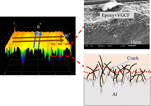
The above exploration reveals that the acid etching treatment on the aluminum surface and incorporation of proper content of VGCF at the interface of the GFRP/Al laminates result in significant enhancement of interlaminar mode II fracture toughness. The reinforcement and toughening effects of rolling stripes on aluminum plates for the 90° specimens may be explained as follows. In this case, the rolling stripes are perpendicular to the fiber direction and the crack propagating direction as shown in figure . During the ENF test, the rolling stripes will hinder the crack propagation at the interface of the Al and GFRP layers which may force the crack deviated from the interface to the epoxy resin layer, therefore causing much more cohesive failure. This improvement mechanism is just the same as that described by Kim and Yun et al [Citation32, Citation33]. They make a patterned line on the metal surface to enhance the fracture toughness of FMLs. Here, the so-called ‘patterned lines’ are the rolling stripes formed in the manufacture process of Al plates. While for the 0° specimens, the rolling stripes are parallel to the fiber and crack propagating direction, which cannot impede the crack propagation as effectively as the 90° specimens. From the results mentioned in section 3.1, it can be found that the fracture toughness values of Plain-0° and Plain-90° are almost the same, while after acid etching treatment and addition of VGCF, the fracture toughness values of the 90° specimens are obviously higher than that of the corresponding 0° specimens. This is because before acid etching treatment, the sizes of rolling stripes are very small, which is not big enough to lead the reinforcement effect. However, after acid etching treatment, the rolling stripes become more obvious and their sizes increase as evidenced by figure . The reason might be the different reaction speeds at the groove and bulge regions. Therefore, the fracture toughness of the 90° specimen is higher than that of the 0° specimen after acid etching treatment. Moreover, when VGCF is added into the interface of Al and GFRP, it will be dispersed into the grooves and hole during the curing process as shown in figure . VGCF will be broken or pulled out from the epoxy resin in the crack propagation process which further improves the reinforcement effects of the rolling stripes.
Figure 14 Schematic illustration of the toughening mechanism of the rolling stripes.
Conclusions
In this work, we systematically investigated the effect of acid etching treatment and VGCF interlayer on the mode II interlaminar fracture toughness of GFRP/Al laminates. The effect of the angle between the rolling stripes of the aluminum plate and the fiber direction was investigated. The experimental results of the ENF test confirmed that with proper addition of VGCF and acid etching treatment, the mode II fracture toughness of GFRP/Al laminates can be greatly improved. The 90° specimens had much higher mode II fracture toughness than that of the 0° specimens. The 385% increase of mode II fracture toughness was achieved in the 90° specimens with the acid treatment and 10 g m−2 VGCF addition. Furthermore, numerical simulations confirmed the experimental fracture toughness and successfully predicted the interfacial shear strength between the aluminum plates and GFRP laminates. The improvement mechanisms were thoroughly explored by the observation of the crack propagation path and fracture surfaces.
Acknowledgements
This work is partly supported by the Research Funds from National Natural Science Foundation of China (No. 11372104) to NH and (No. 11332013) to XP, and Grant-in-Aid for Scientific Research (No. 21226004) from the Japanese Ministry of Education, Culture, Sports, Science and Technology to NH.
References
- ChangP YYehP CYangJ M 2008 Mater. Sci. Eng. A 496 273 10.1016/j.msea.2008.07.041
- YamaguchiTOkabeTKosakaT 2010 Adv. Compos. Mater. 19 107 10.1163/092430410X490428
- ZhangSPanatRHsiaK J J 2003 J. Adhes. Sci. Technol. 17 1685 10.1163/156856103322396749
- JangC JKimW SKimH CLeeJ JJeongJ W 2011 Procedia. Eng. 10 2585 10.1016/j.proeng.2011.04.426
- AlfanoMLubineauGFurgiueleFPaulinoG H 2012 Int. J. Adhes. Adhes. 39 33 10.1016/j.ijadhadh.2012.03.002
- RheeK YLeeS GChoiN SParkS J 2003 Mater. Sci. Eng. A 357 270 10.1016/S0921-5093(03)00207-7
- ReyesGGuptaS 2009 Composites A 40 176 10.1016/j.compositesa.2008.10.016
- MelogranaJ DGrenestedtJ LMarounW J 2003 Composites A 34 119 10.1016/S1359-835X(03)00005-8
- MolitorPYoungT 2002 Int. J. Adhes. Adhes. 22 101 10.1016/S0143-7496(01)00041-0
- RechnerRJansenIBeyerE 2010 Int. J. Adhes. Adhes. 30 595 10.1016/j.ijadhadh.2010.05.009
- ShuDMaiY W 1993 Compos. Sci. Technol. 49 165 10.1016/0266-3538(93)90056-M
- AymerichFOnnisRPrioloP 2005 Composites A 36 603 10.1016/j.compositesa.2004.08.003
- ChangPMourtizA PCoxB N 2006 Compos. Sci. Technol. 66 2163 10.1016/j.compscitech.2005.11.039
- ByrdL WBirmanV 2006 Composites B 37 365 10.1016/j.compositesb.2005.05.019
- AraiMNoroYSugimotoKEndoM 2008 Compos. Sci. Technol. 68 516 10.1016/j.compscitech.2007.06.007
- KhanS UKimJ K 2012 Carbon 50 5265 10.1016/j.carbon.2012.07.011
- LeeS HKimHHangSCheongS K 2012 Compos. Sci. Technol. 73 1 10.1016/j.compscitech.2012.09.011
- YasaeeMBondI PTraskR SGreenhalghE S 2012 Composites A 43 121 10.1016/j.compositesa.2011.09.026
- HojoMAndoTTanakaMAdachiTOchiaiSEndoY 2006 Int. J. Fatigue 28 1154 10.1016/j.ijfatigue.2006.02.004
- MagniezKChaffraixTFoxB 2011 Materials 4 1967 10.3390/ma4111967
- FosterR JBonnerM JWardI M 2011 Compos. Sci. Technol. 71 461 10.1016/j.compscitech.2010.12.019
- SiddiquiN AKhanS ULiC YMaP CKimJ K 2011 Composites A 42 1412 10.1016/j.compositesa.2011.06.005
- HudnutS WChungD D L 1995 Carbon 33 1627 10.1016/0008-6223(95)00148-7
- SegietMChungD D L 2000 Compos. Interface. 7 257 10.1163/156855400750244978
- LiYHoriNAraiMHuNLiuY LFukunagaH 2009 Composites A 40 2004 10.1016/j.compositesa.2009.09.002
- Japanese Industrial Standard Group 1993 JIS K 7086-1993 651
- LeeS HNoguchiHKimY B 2002 J. Compos. Mater. 36 2153 10.1177/0021998302036018981
- RussellA JStreetK N 1982 Proc. 4th Int. Conf. on Composite Materials (ICCM-IV) (Tokyo, Japan)
- O’BrienT K 1998 Compos. Mater. Fatigue Fract. 7 3
- HuNZembaYFukunagaHWangH H 2007 Compos. Sci. Technol. 67 752 10.1016/j.compscitech.2006.04.014
- HuNZembaYOkabeTChengYFukunagaHElmarakbiA M 2008 Mech. Mater. 40 920 10.1016/j.mechmat.2008.05.003
- KimW SYunI HLeeJ JJungH T 2010 Int. J. Adhes. Adhes. 30 408 10.1016/j.ijadhadh.2010.05.004
- YunI HKimW SKimK HJungJ MLeeJ JJungH T 2011 J. Appl. Phys. 109 074302 10.1063/1.3567113