
Abstract
This review article summarizes the recent achievements in stabilization of the metastable lattice of gadolinium aluminate garnet (Gd3Al5O12, GAG) and the related developments of advanced optical materials, including down-conversion phosphors, up-conversion phosphors, transparent ceramics, and single crystals. Whenever possible, the materials are compared with their better known YAG and LuAG counterparts to demonstrate the merits of the GAG host. It is shown that novel emission features and significantly improved luminescence can be attained for a number of phosphor systems with the more covalent GAG lattice and the efficient energy transfer from Gd3+ to the activator. Ce3+ doped GAG-based single crystals and transparent ceramics are also shown to simultaneously possess the advantages of high theoretical density, fast scintillation decay, and high light yields, and hold great potential as scintillators for a wide range of applications. The unresolved issues are also pointed out.
1. Introduction
Rare-earth aluminate garnets, having a general formula of Ln3Al5O12 (LnAG, Ln: lanthanide and Y), are an important family of multi-functional ceramic materials. The compounds crystallize in a bcc structure (space group: with 160 (80) atoms in the cubic (primitive) cell, where the Ln occupies the 24c sites (D2 point symmetry, CN = 8; CN: coordination number) and the oxygen atoms take the 96h sites. The Al atoms have two positions to reside on: the 16a sites with an octahedral point symmetry (C3i, 40%; CN = 6) and the 24d sites with a tetragonal point symmetry (S4, 60%; CN = 4) [Citation1]. The garnet structure can be viewed as a framework built up via corner sharing of the Al–O polyhedra, with the Ln residing in dodecahedral interstices [Citation1]. A schematic diagram of the crystal structure is shown in figure .
Figure 1. A schematic illustration of the crystal structure of LnAG, where Aloct and Altet represent the Al atoms taking octahedral and tetrahedral lattice sites, respectively. Adapted with permission from [Citation1], copyright 1999 by the American Physical Society.
![Figure 1. A schematic illustration of the crystal structure of LnAG, where Aloct and Altet represent the Al atoms taking octahedral and tetrahedral lattice sites, respectively. Adapted with permission from [Citation1], copyright 1999 by the American Physical Society.](/cms/asset/052eff98-ad2e-40bd-a47a-c2f11db25357/tsta_a_11661245_f0001_ob.jpg)
YAG might be the best-known garnet compound owing to its excellent chemical stability, high creep resistance, optical isotropy, and particularly the ability to accept substantial trivalent Ln3+ for diverse optical functionalities. In the bulk form, the YAG:Nd single crystal is one of the most widely used solid laser materials since its discovery in the 1960s [Citation2]. Transparent YAG:Nd ceramics that are equal to or superior to single crystals in optical transmittance and laser performance have also been successfully developed since the 1990s via advanced powder processing and sintering technologies [Citation3, Citation4]. YAG:Ho3+ and YAG:Er3+ are important infrared (IR) laser materials for medical surgery, since their fluorescence lines (∼2 μm for Ho3+ and ∼3 μm for Er3+) match well with the water absorptions of the human body [Citation5]. Transparent YAG:Ce3+ ceramic is nowadays being developed as an encapsulant for white-light emitting diodes (LEDs) to replace the widely used but readily degradable resin sealant [Citation6]. Since the parity-law allowed 4f05d1 → 4f15d0 transition of Ce3+ has a very short fluorescence lifetime of ∼10–100 ns and the intrinsic quenching temperature of Ce3+ in YAG is very high (>700 K) [Citation7], YAG:Ce3+ transparent ceramic has been considered as a scintillator [Citation8], but does not seem to have a satisfactory stopping power for the incident radiations (x-, α- or γ-rays) owing to the relatively low theoretical density of YAG (∼4.55 g cm−3) and the small atomic weight of Y (∼89). In the powder form, rare-earth (Eu3+, Tb3+, Ce3+ etc) activated YAG is being widely studied and used as phosphors for fluorescent lamps, field emission displays (FEDs), and white LEDs.
The occurrence and thermal stability of compounds in the Ln2O3–Al2O3 binary system heavily depend on the ionic radius of Ln3+, conforming to lanthanide contraction. Earlier studies by Mizuno et al [Citation9–Citation13] on the phase diagram of Ln2O3–Al2O3 found the two intermediate compounds of Ln2O3·11Al2O3 (β-Al2O3 type) and LnAlO3 (commonly referred to as aluminate perovskite or LnAP, an orthorhombic modification of ideal perovskite) for the large ions of La3+–Nd3+, the two compounds of LnAP and monoclinic Ln4Al2O9 (commonly called LnAM) for the intermediately sized Sm3+–Gd3+, and the three compounds of LnAM, LnAP, and LnAG for the small Ln3+ ions of Tb3+–Er3+. Though GdAG (further abridged as gadolinium aluminate garnet (GAG) hereafter) was not identified in the work of Mizuno et al, it was successfully synthesized via flux growth by Van Uitert et al [Citation14] and Manabe and Egashira [Citation15] for potential optical applications. Later on, Shishido et al [Citation16] found via annealing Gd2O3·5/3Al2O3 amorphous glass that GAG is metastable and would completely decompose to α-Al2O3 and GdAP (Gd3Al5O12 → Al2O3 + 3GdAlO3) upon prolonged annealing at 1500 °C. A recent work by Li et al [Citation17] further showed that the stoichiometric GAG synthesized via low temperature combustion starts to decompose at ∼1300 °C. All these studies point to the fact that thermodynamically stable LnAG only exists for the Ln3+smaller than Gd3+ and Gd3+ is the boundary for a LnAG to be formed. This is understandable from the crystal structure shown in figure . That is, the dodecahedral interstice has a certain geometric shape and dimension, and thus a size limit exists for Ln3+ to enter the space without disintegrating the Al–O framework. Mainly due to its structural metastability, GAG has been much less explored than YAG for its properties and applications, though its specific heat and thermal expansion coefficient were experimentally determined by Chaudhury et al [Citation18]. Compared with YAG, however, GAG may hold a number of merits for optical applications: (1) the intrinsic 8S7/2 → 6IJ transition of Gd3+ (usually centered at ∼275 nm) can be utilized as a new excitation source for some types of rare-earth activators, and enhanced luminescence may also be attained via an efficient energy transfer from Gd3+ to the activator [Citation19–Citation22], (2) the GAG lattice is more covalent than YAG due to the lower electronegativity of Gd3+ (χ = 1.20) than Y3+ (χ = 1.22), which may produce new emission features and result in improved emission intensity, and (3) GAG has a significantly higher theoretical density (5.97 g cm−3) than YAG (4.55 g cm−3) and the atomic weight of Gd (157, close to the 175 of Lu) is much higher than Y, and thus GAG is more desirable for scintillation applications. Similar to the growth of single crystals and sintering of transparent ceramics, a reasonably high processing temperature is usually needed to produce high quality phosphors through crystal perfection. In this context, lattice stabilization becomes a prerequisite for any practical application of GAG in advanced optical materials. This review article summarizes the recent achievements in GAG, including lattice stabilization via doping and its application in down-/up-conversion (UC) phosphors and transparent ceramic/single crystal scintillators.
2. Lattice stabilization of GAG by modifying the Gd/Al sites
There are two primary ways to stabilize the garnet lattice of GAG, as can be perceived from the crystal structure shown in figure , with the first one partially replacing the Al sites with suitably larger trivalent ions to enlarge the dodecahedral interstices via forming Gd3(Al1−xMx)5O12 solid solution and the second one being partially replacing Gd3+ with a smaller Ln3+ to form (Gd1−xLnx)3Al5O12. Ga3+ is the main choice in the former case, and Gd3Ga5O12 (GGG), known as a thermodynamically stable garnet host for phosphors and solid lasers [Citation2], is an extreme example. The effectiveness of Ga3+ doping was experimentally demonstrated by Chiang et al [Citation23], who found that phase-pure garnet can be crystallized from chemically precipitated precursors at ∼1400 °C in the presence of 10 at% of Ga3+ and the crystallization temperature decreases to 1300 °C with 20 at% of Ga3+ addition. Without Ga3+ doping, only a phase mixture of LnAP, LnAG and amorphous alumina was formed. By applying the same stabilization strategy, Kamada et al were able to grow two-inch-diameter Gd3(Al2Ga3)O12:Ce3+ single crystals by the Czochralski (Cz) method using [Citation100] oriented seeds [Citation24] and Gd3(Ga,Al)5O12:Pr3+ single crystals by a micro-pulling down (μ-PD) technique [Citation25] (figure ). Though Ga3+ was thought to exclusively replace Al3+ in these studies, atomistic modeling using the static lattice computational approach and pairwise (Buckingham) interatomic potentials by Maglia et al [Citation26] revealed that Ga3+, though it prefers to take the octahedral Al3+ site, can also be inserted into the dodecahedral position of Gd3+ with the generation of anti-site defects owing to its relatively large ionic radius. In addition, suppressing activator oxidation (such as Pr3+, Ce3+, and Tb3+) and Ga3+ reduction should be made at the same time to avoid lattice defects and deterioration of optical performance.
Figure 2. Appearance of the Gd3(Al2Ga3)O12 single crystals doped with 1 at% of Ce3+ (a) and 1 at% of Pr3+ (b). Part (a) reproduced with permission from [Citation24] and part (b) reproduced with permission from [Citation25], copyright 2012 by Elsevier.
![Figure 2. Appearance of the Gd3(Al2Ga3)O12 single crystals doped with 1 at% of Ce3+ (a) and 1 at% of Pr3+ (b). Part (a) reproduced with permission from [Citation24] and part (b) reproduced with permission from [Citation25], copyright 2012 by Elsevier.](/cms/asset/927f835b-640c-4b6d-acdc-dbd7563f1bbd/tsta_a_11661245_f0002_oc.jpg)
Lu3+ (0.0977 nm for CN = 8) is the tiniest Ln3+ ion and would thus be the most effective to stabilize GAG via replacing the Gd3+ site to form a (Gd1−xLux)AG solid solution. With coprecipitated carbonate precursors, Li et al [Citation17] thoroughly studied the effects of Lu content on phase evolution and also properties of the resultant (Gd1−xLux)AG (x = 0–0.5). It was shown that the garnet phase generally crystallizes via LnAM and LnAP intermediates, as is commonly observed for YAG, but the crystallization temperature substantially decreases towards a higher Lu content. With x = 0.3–0.5, phase-pure garnet can even be crystallized at a temperature as low as 1000 °C (figure (a)), revealing the significant effectiveness of Lu3+ doping. Again, only a phase mixture of LnAG, LnAP and amorphous Al2O3 was produced in the absence of Lu3+ (figure (b)).
Figure 3. The effects of Lu content (x value) on phase evolution of (Gd1−xLux)AG solid solution. Parts (a) and (b) are for calcination temperatures of 1000 and 1500 °C, respectively. Reproduced with permission from [Citation17], copyright 2012 by the American Ceramic Society.
![Figure 3. The effects of Lu content (x value) on phase evolution of (Gd1−xLux)AG solid solution. Parts (a) and (b) are for calcination temperatures of 1000 and 1500 °C, respectively. Reproduced with permission from [Citation17], copyright 2012 by the American Ceramic Society.](/cms/asset/c090e71e-a1b6-4c49-a112-ad8b4271faa3/tsta_a_11661245_f0003_ob.jpg)
A simultaneous advantage of Lu doping is that it improves the already high theoretical density of GAG (5.97 g cm−3). The (Gd0.5Lu0.5)AG solid solution, for example, reaches the high value of ∼6.44 g cm−3 (figure (a)), being close to that of the heavy LuAG (6.73 g cm−3). Since Gd is commercially much cheaper than Lu, the (Gd1−xLux)AG solid solutions may replace LuAG to be used as cost effective and high density scintillation materials. Assayed from UV/vis absorption, the (Gd1−xLux)AG solid solutions were found to have increasing optical bandgaps of ∼5.87, 5.97, 6.07, 6.17, 6.27, and 6.37 eV with increasing x from 0 to 0.5 (0.1 interval, figure (b)) [Citation17], and the bandgap of (Gd0.5Lu0.5)AG has been close to that (∼6.40 eV) of a YAG single crystal [Citation27]. The results may also imply that the luminescence property of a (Gd, Lu)AG based phosphor can be finely tuned by varying the Lu content and the onset of optical transmittance of a transparent (Gd, Lu)AG bulk (single crystal or transparent ceramic) would shift towards a shorter wavelength with increasing Lu incorporation.
Figure 4. Lattice constant and theoretical density (a) and bandgap (b) of the (Gd1−xLux)AG solid solution, as a function of the Lu content. Part (a) reproduced with permission from [Citation17], copyright 2012 by the American Ceramic Society.
![Figure 4. Lattice constant and theoretical density (a) and bandgap (b) of the (Gd1−xLux)AG solid solution, as a function of the Lu content. Part (a) reproduced with permission from [Citation17], copyright 2012 by the American Ceramic Society.](/cms/asset/0fe32d57-fe31-4fc5-9525-f1797e54b88f/tsta_a_11661245_f0004_ob.jpg)
Tb3+ is the largest single Ln3+ for a stable LnAG to be formed, and thus its size can be taken as a reference for a lattice stabilization study of GAG. The minimum amount of Lu3+ (∼17 at%) calculated from the ionic size of Tb3+ (0.1040 nm for CN = 8), however, is significantly larger than the ∼10 at% found in practice (figure (b)). This indicates that stable garnet solid solutions exist if the average ionic size of (Ln1,Ln2)3+ pair lies in between those of Gd3+ (0.1053 nm for CN = 8) and Tb3+, in agreement with the fact that TbAG [Citation28–Citation30] and even (Gd0.9Lu0.1)AG [Citation31, Citation32] can be further doped with larger Eu3+ (0.1066 nm, CN = 8) and Ce3+ (0.1143 nm, CN = 8) for luminescence. Taking the average ionic size of (Gd0.9Lu0.1)3+ (~0.1045 nm) as a standard, Li et al [Citation33] analyzed the minimum amounts of various small Ln3+ that are needed for GAG stabilization, and the x value was predicted to be ∼0.5 for Tb3+, 0.3 for Dy3+ (0.1027 nm), 0.22 for Y3+ (0.1019 nm), 0.2 for Ho3+ (0.1015 nm), 0.15 for Er3+ (0.1004 nm), 0.13 for Tm3+ (0.0994 nm), and 0.11 for Yb3+ (0.0985 nm). Practical powder synthesis indeed shows that (Gd1−xLnx)AG garnet can be obtained in high phase purity with incorporation of the calculated amount of dopant in each case (figure ). The results may thus lay a base for flexible materials design by properly combining different types of stabilizers to achieve diverse optical functionalities. The characteristic emission of Ln3+ in (Gd0.5Ln0.5)AG was observed by the authors for Tb (green), Dy (similarly strong blue and yellow), Ho (green), and Tm (blue), despite the high Ln3+ concentration (figure ).
Figure 5. Powder XRD patterns of the phase pure (Gd1−xLnx)AG garnets obtained by doping GAG with the calculated amount (x value) of different Ln3+. Reproduced with permission from [Citation33], copyright 2013 by Trans Tech Publications.
![Figure 5. Powder XRD patterns of the phase pure (Gd1−xLnx)AG garnets obtained by doping GAG with the calculated amount (x value) of different Ln3+. Reproduced with permission from [Citation33], copyright 2013 by Trans Tech Publications.](/cms/asset/0d70a1ca-dfad-4e5d-87cf-f72907860ccc/tsta_a_11661245_f0005_ob.jpg)
Figure 6. Emission spectra for the (Gd0.5Ln0.5)AG solid solution, with the excitation wavelength (Ex) and the origin of luminescence indicated. Reproduced with permission from [Citation33], copyright 2013 by Trans Tech Publications.
![Figure 6. Emission spectra for the (Gd0.5Ln0.5)AG solid solution, with the excitation wavelength (Ex) and the origin of luminescence indicated. Reproduced with permission from [Citation33], copyright 2013 by Trans Tech Publications.](/cms/asset/bb2e633b-442e-4649-b3d8-9de5b1a2f9dc/tsta_a_11661245_f0006_ob.jpg)
3. Down-conversion (DC) phosphors based on GAG
DC phosphors are generally referred to those that absorb high-energy photons and re-emit them at longer wavelengths in the visible range. There are many host lattices for DC luminescence, and the most extensively employed ones may include single-/multi-cation oxides, oxysulfides, phosphates, vanadates, borates, and molybdates/tungstates. Different hosts are used in practice to meet different application needs. Though almost all of the optically active Ln3+ can be used as the activator for DC luminescence, the four ions of Ce3+, Eu3+, Tb3+, and Dy3+ are the most efficient since their energy gaps between the lowest emission state and ground state are sufficiently wide to avoid significant non-radiative cross relaxations. The emission behaviors of these activators are generally governed by their site symmetry in the host lattice, lattice covalency, lattice defects/distortion, and particle size/shape (surface effects).
3.1. Eu3+ doping for red luminescence
Eu3+ is well known for its orange red/red emission arising from the 5D0 → 7F1,2 electronic transitions. The Eu3+ ions doped in LnAG are assumed to replace the Ln3+ sites and thus inherit a D2 point symmetry, which is only slightly perturbed from the highly symmetric D2h point group [Citation34]. For this, the emission of YAG:Eu and LuAG:Eu is dominated by the parity-law allowed 5D0 → 7F1 magnetic dipole transition at ∼590 nm rather than the forced 5D0 → 7F2 electric dipole transition at ∼610 nm as observed from the well-known Y2O3:Eu red phosphor. A [(Gd1−xLux)1−yEuy]AG solid solution has recently been developed as efficient red phosphor with Lu3+ as the lattice stabilizer, and the effects of various factors on optical properties were thoroughly investigated [Citation31]. Taking [(Gd0.7Lu0.3)1−yEuy]AG for example, the material was shown to be efficiently excitable with the charge transfer band (CTB) at ∼239 nm to produce a sharp orange–red emission at 591 nm (figure ), with CIE chromaticity coordinates of (0.62, 0.38) and a full width at half maximum of only ∼6 nm for the emission peak. The optimal Eu3+ content was experimentally determined to be ∼5 at% (y = 0.05), and the quenching mainly resulted from exchange interactions, possibly via phonon assisted three Eu3+ ion nonresonant interactions. Greatly improved emission intensity and quantum yield, shortened fluorescence lifetime, and increased asymmetry factor of luminescence (the I591/I610 intensity ratio) were observed along with increasing synthesis temperature up to 1500 °C [Citation31], primarily owing to lattice perfection, defect elimination, and particle growth. The [(Gd0.7Lu0.3)0.95Eu0.05]AG phosphor synthesized at 1500 °C has internal/external quantum efficiencies (%) of 83.2/56.1, an asymmetry factor of ∼2.85, and a fluorescence lifetime of ∼4.1 ms for the 591 nm emission [Citation31]. The lifetime is close to that (4.66 ms) reported for YAG:Eu [Citation35] but is significantly longer than those (generally 0.5–2.5 ms) of the well-known red phosphors of Y2O3:Eu [Citation36, Citation37], (Gd1−xLnx)2O3:Eu (Ln = Y, Lu) [Citation22, Citation38], and La2O2S:Eu [Citation39], since the Eu3+ activator takes the highly symmetric D2 lattice site in garnet. Increasing Lu incorporation up to x = 0.5 would lower excitation/emission and also blue-shift the CTB due to gradually decreased covalency of the host lattice (χ = 1.27 for Lu3+), for which a minimized Lu content was recommended as long as the garnet lattice can be effectively stabilized [Citation31]. Similar phenomena were observed in the development of (Gd1−xLnx)2O3:Eu red phosphors (Ln = Y, Lu) [Citation38]. Compared with YAG:Eu, the GAG-based phosphor (figure ) has an additional excitation band arising from the 8S7/2 → 6IJ Gd3+transition at ∼275 nm (significantly stronger than the strongest 7F0,1 → 5L6 intra-4f6 transition of Eu3+ at ∼395 nm), suggesting substantial energy migration from Gd3+ to Eu3+. The advantage of GAG over YAG as a host lattice was demonstrated in another study by the authors [Citation40]. For example, the internal quantum yield (∼76%) of [(Gd0.9Lu0.1)0.95Eu0.05]AG is appreciably higher than that (∼71%) of (Y0.95Eu0.05)AG at the same temperature of phosphor synthesis. This is primarily owing to the higher lattice covalency of the former, which allows improved excitation absorption and higher probability of electronic transitions. Though [(Gd1−xLux)0.95Eu0.05]AG has had a sufficiently high theoretical density and emission intensity, its fluorescence lifetime is too long for scintillation. Shortening the lifetime to below ∼1.0 ms via codoping (such as Pr3+) seems necessary for it to compete with the commercialized (Y,Gd)2O3:Eu scintillator [Citation41].
Figure 7. Excitation and emission behaviors of the [(Gd0.7Lu0.3)1−yEuy]AG red phosphors. Reproduced with permission from [Citation31], copyright 2012 by the National Institute for Materials Science.
![Figure 7. Excitation and emission behaviors of the [(Gd0.7Lu0.3)1−yEuy]AG red phosphors. Reproduced with permission from [Citation31], copyright 2012 by the National Institute for Materials Science.](/cms/asset/ca4ecb01-bc09-4a30-b9d4-14323fa25c91/tsta_a_11661245_f0007_ob.jpg)
The carbonate coprecipitation technique, with ammonium bicarbonate as the precipitant, has been able to produce low-aggregation garnet powders, but the primary particles are not separable from each other and are not in a spherical shape (figure (a)). Current advances in high-resolution displays not only need finer phosphor particles to improve the resolution by decreasing pixel size but also prefer a spherical particle shape to build a uniform luminescence screen and to improve the brightness of luminescence by minimizing the light scattering on particle surfaces. Urea-based homogeneous precipitation (UBHP) frequently finds success in synthesizing well-dispersed spherical particles of uniform size (monosheres) for single-/multi-cation oxides of the lanthanides [Citation19, Citation42–Citation48], but failed for YAG in most of the previous studies [Citation49, Citation50] owing to substantially different solution chemistries of the constituent Y3+ and Al3+ ions. YAG:Ce phosphor microspheres are thus alternatively made via crystallizing the glassy microbeads quenched from melt droplets produced with laser heating [Citation51]. Xu et al [Citation52] identified that, with nitrate as the rare-earth source in UBHP, the aluminum source plays an essential role in the formation of precursor microspheres for YAG:Nd. They found that ammonium aluminum sulfate (alum) is indispensable and the optimal alum/Al(NO3)3 molar ratio is 1/1. Mechanistic study further revealed that microspheres of the Al component are formed at the early stage of precipitation, followed by Y3+ precipitation as basic carbonate. Annealing the sulfate-containing precursor at 1100 °C produced YAG:Nd microspheres that can be densified to a translucent state via vacuum sintering of the dry-compacted green body at 1650 °C for 3.5 h. Such a strategy proved similarly successful for [(Lu1−xGdx)0.95Eu0.05]AG red phosphor microspheres (x ≤ 0.4, figure (b)) [Citation53], though Gd3+ and Lu3+ are different from Y3+ in solution chemistry owing to lanthanide contraction. Again, the best results were obtained with alum/Al(NO3)3 = 1:1 molar ratio. When Al(NO3)3 is the sole Al source, only a gelatinous precursor that would aggregate into a glasslike hard mass upon drying was produced, implying that the sulfate anions from alum have significantly modified the solution chemistry of cations, particularly that of the significantly smaller Al3+, and have taken part in precipitation. When the alum/Al(NO3)3 ratio is over 1, the primary spheres tend to glue together to form porous precipitates as observed for YAG [Citation50], suggesting that superfluous SO42− may serve as a flocculant. The diameter of [(Lu1−xGdx)0.95Eu0.05]AG microspheres can be finely tuned from ∼500 to 150 nm by increasing the urea/(Al+Ln) molar ratio from 20 to 100, showing the flexibility of the UBHP technique. A photoluminescence study [Citation53] found successively stronger 5D0 → 7F1 emission (591 nm) with increasing x (the Gd content), owing to increased lattice covalency (figure (c)), and gradually weaker emission at a decreasing particle size owing to surface effects [Citation47, Citation54].
Figure 8. Typical TEM (a) and SEM (b) morphologies of the [(Lu1−xGdx)0.95Eu0.05]AG red phosphor particles obtained via carbonate coprecipitation and urea-based homogeneous precipitation, respectively. Part (c) shows that the emission intensity of the phosphor spheres improves with increasing Gd content. Parts (a) and (b) reproduced from [Citation31], copyright 2012 by the National Institute for Materials Science.
![Figure 8. Typical TEM (a) and SEM (b) morphologies of the [(Lu1−xGdx)0.95Eu0.05]AG red phosphor particles obtained via carbonate coprecipitation and urea-based homogeneous precipitation, respectively. Part (c) shows that the emission intensity of the phosphor spheres improves with increasing Gd content. Parts (a) and (b) reproduced from [Citation31], copyright 2012 by the National Institute for Materials Science.](/cms/asset/5f97653f-7c5f-4924-be71-6e48c19cba8b/tsta_a_11661245_f0008_oc.jpg)
3.2. Ce3+ doping for yellow luminescence
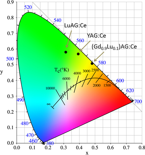
The yellow emission of Ce3+ arises from the 4f05d1 → 4f15d0 (2F5/2 and 2F7/2 ground states) inter-configurational electronic transition. As the exposed 5d electron readily interacts with the surrounding anion ligands, Ce3+ emission is strongly influenced by centroid shifting and crystal field splitting of the 5d energy level (figure ) [Citation55]. YAG:Ce3+ has been the most prominent and widely used yellow phosphor in LED lighting, since it can be efficiently excited with (Ga, In)N blue LED chips (∼450 nm) and exhibits a high quantum yield of ∼90% for its ∼540 nm emission [Citation7]. One shortcoming is that, for warm-white lighting, YAG:Ce3+ has low color rendering and high correlated color temperature due to its lack of a sufficient red portion in the emission spectrum. To overcome this, partially replacing the Y3+ sites with less electronegative La3+ or Gd3+ [Citation6, Citation56] and more recently doping YAG with Si3N4 to form the oxynitride solid solution of Y2.925Ce0.075Al5−xSixO12−xNx (x < 0.4 for phase pure garnet) [Citation57] were shown to be able to push down the lowest crystal-splitting component (2D3/2) of the 5d1 excited level to yield red-shifted emissions. Red-shifting can also be achieved by partially substituting Al3+ with Mg2+–Si4+ pairs on the octahedral and tetrahedral sites, respectively, to enhance lattice covalency [Citation58, Citation59]. Alternatively, red-shifted Ce3+ emission can be directly attained with a more covalent host lattice, such as TbAG and GAG-based garnets. With single crystal films, Zorenko et al [Citation29] found that TbAG:Ce exhibits broad band emission peaking at 550 nm under 470 nm excitation [4f1(2F5/2) → 5d1(E2g) Ce3+ transition], with light yields of ∼62–71% depending on the Ce3+ content. An efficient Tb3+ → Ce3+ energy transfer was identified through directly exciting the Tb3+ ions in the host lattice at 325 nm. Chiang et al [Citation23] found that the emission wavelength of Ga3+-stabilized (Gd0.97Ce0.03)3(Al1−xGax)5O12 yellow phosphors gradually shortens from ∼565 to 552 nm (λex = 470 nm) with increasing Ga3+ substitution from x = 0.1 to 0.3, yet substantially longer than the ∼540 nm emission of YAG:Ce, and the shortening was ascribed to the higher electronegativity of Ga3+ (χ = 1.81) than Al3+ (χ = 1.61). Li et al [Citation32] studied in detail the synthesis and optical properties of [(Gd1−xLux)1−yCey]AG yellow phosphors. It was found that 1 at% (y = 0.01) of much larger Ce3+ (0.1143 nm) can be doped into the garnet lattice in the presence of 10 at% of Lu (x = 0.1) and more Ce3+ needs more Lu3+. The optimal Ce3+ concentration was experimentally determined to be ∼1 at%, and luminescence quenching mainly resulted from exchange interactions. Intensity ratio (Ib/Ia) of the 460 nm [4f1(2F5/2) → 5d1(E2g)] to 340 nm [4f1(2F5/2) → 5d1(T2g)] excitations was observed to significantly increase from ∼4.8 at y = 0.01 to ∼9.0 at y = 0.02 and then to ∼12 at y = 0.03, due to successively stronger non-radiative absorptions. Energy transfer from Gd3+ to Ce3+ was identified from the appearance of 8S7/2 → 6IJ Gd3+ transition at ∼275 nm. Figure compares the emission spectra of [(Gd1−xLux)0.99Ce0.01]AG (λex = 455 nm), (Y0.99Ce0.01)AG (λex = 454 nm), and (Lu0.99Ce0.01)AG (λex = 448 nm), from which it is seen that the emission covers the broad range of ∼475–750 nm in each case and the peak wavelength of [(Gd1−xLux)0.99Ce0.01]AG red-shifts relative to those of YAG:Ce and LuAG:Ce even at the high Lu content of 50 at% (x = 0.5). Increasing Lu incorporation steadily shortens the emission wavelength due to decreased lattice covalency by the high electronegativity of Lu3+ (χ = 1.27) and monotonically lowers the emission intensity possibly owing to lattice distortion and defect introduction. The best luminescent [(Gd0.9Lu0.1)0.99Ce0.01]AG has an integrated emission intensity ∼97% of (Y0.99Ce0.01)AG and ∼128% of (Lu0.99Ce0.01)AG at the same temperature of powder synthesis. The excellent emission, high theoretical density, and relatively low cost of [(Gd0.9Lu0.1)0.99Ce0.01]AG may allow it to compete with YAG:Ce and particularly LuAG:Ce for scintillation applications. CIE chromaticity coordinates (figure ) of the three phosphors are around (0.48, 0.51), (0.39, 0.57), and (0.31, 0.58), corresponding to color temperatures of ∼3044, 4612 and 6010 K, respectively. The chromaticity data again confirm that the GAG-based yellow phosphor has a stronger red component in its emission and is more desirable for warm-white LED lighting.
Figure 9. A schematic energy diagram showing the effects of host lattice A on centroid shift and crystal field splitting of the Ce3+ 5d energy level. Such effects shorten the energy difference between the 5d excited state and 4f ground state, known as red-shift D(A). Reproduced with permission from [Citation55], copyright 2013 by Annual Reviews Inc.
![Figure 9. A schematic energy diagram showing the effects of host lattice A on centroid shift and crystal field splitting of the Ce3+ 5d energy level. Such effects shorten the energy difference between the 5d excited state and 4f ground state, known as red-shift D(A). Reproduced with permission from [Citation55], copyright 2013 by Annual Reviews Inc.](/cms/asset/48cab29a-fc02-40da-b227-29dc73d73d11/tsta_a_11661245_f0009_oc.jpg)
Figure 10. Emission spectra for the [(Gd1−xLux)0.99Ce0.01]AG, (Lu0.99Ce0.01)AG, and (Y0.99Ce0.01)AG yellow phosphors. Reproduced with permission from [Citation32], copyright 2013 by the National Institute for Materials Science.
![Figure 10. Emission spectra for the [(Gd1−xLux)0.99Ce0.01]AG, (Lu0.99Ce0.01)AG, and (Y0.99Ce0.01)AG yellow phosphors. Reproduced with permission from [Citation32], copyright 2013 by the National Institute for Materials Science.](/cms/asset/51da95cc-b570-4ca9-8272-1fedae8cc68e/tsta_a_11661245_f0010_oc.jpg)
Figure 11. Emission color coordinates for the (Gd, Lu)AG:Ce, YAG:Ce, and LuAG:Ce yellow phosphors.
3.3. Tb3+ doping for green luminescence
When a Tb3+ activator is excited with light of sufficient energy, such as UV light, its 4f8 electrons would be raised to the higher 4f75d1 level and then fed to the 5D3,4 excited states, from which fluorescence is produced by transitions to the 7FJ (J = 1–6) ground states. Though the excited 5d electron is exposed, Tb3+ transitions involve only a redistribution of electrons within the inner 4f sub-shell [Citation60], and thus similar emissions are usually observed from different types of host lattices, with the 5D4 → 7F5 green emission at ∼545 nm being dominant.
YAG:Tb green phosphors are widely studied for applications in cathode ray tubes and flat panel displays such as FED and electroluminescent display, since it is thermally stable and resists saturation under high-current excitations [Citation61, Citation62]. The GAG-based green phosphor of (Gd, Lu)AG:Tb could be an alternative choice for these purposes and improved performance might also be expected from the possible Gd3+ → Tb3+ energy transfer. The effects of Tb3+ content on photoluminescence of [(Gd0.8Lu0.2)1−xTbx]AG were studied in figure , from which the quenching concentration was determined to be ∼10 at% (x = 0.1), almost identical to that of YAG:Tb [Citation63], and luminescence quenching was suggested to occur via exchange interactions [Citation53]. The excitation spectrum consists of three 4f8 → 4f75d1 transition bands at ∼227 nm (E1–23 level, spin allowed), 276 nm (E1–32 level, spin allowed), and 323 nm (E1 level, spin forbidden), with the 276 nm one being dominant as widely observed [Citation29]. It should be noted that the 8S7/2 → 6IJ Gd3+ transition (∼275 nm) well overlaps the 276 nm excitation, suggesting the likelihood of Gd3+ → Tb3+ energy transfer, since the 6IJ state of Gd3+ lies higher than the 5D3,4 emission states of Tb3+ in the energy diagram of excited states for Ln3+ [Citation64–Citation66]. The emission spectrum obtained under 276 nm excitation has four groups of bands at ∼490 (blue), 545 (green, the strongest), 589 (yellow), and 623 nm (red), corresponding to the 5D4 → 7F6,5,4,3 transitions, respectively. Emission from the higher 5D3 excited level, usually in the 450–490 nm region, is hardly observable, which can be explained by cross-relaxation via resonance between the excited and ground states of two Tb3+ ions, that is, populating the 5D4 level by quenching the 5D3 level via Tb3+ (5D3) + Tb3+ (7F0) → Tb3+ (5D4) + Tb3+ (7F6) [Citation67]. Emission from the 5D3 state was experimentally found for YAG doped with 1 at% [Citation61] but not with 5 at% of Tb3+ [Citation62], and 1 at% is generally accepted as the up-limit for the 5D3 emission to appear in many hosts. It is noteworthy that the charge transfer state (CTS) of the host lattice also determines the occurrence of 5D3 emission [Citation68]. In La2O2S:Tb3+, for example, it is completely quenched even at very low Tb3+ concentrations, not owing to cross relaxation but by thermal excitation of the 5D3 electrons into CTS since the two states have similar energies [Citation68]. Comparative studies showed that the [(Gd1−xLux)0.9Tb0.1]AG phosphors with x = 0.1 and 0.2 have emission intensities close to (Y0.9Tb0.1)AG and (Lu0.9Tb0.1)AG, though the latter two have better crystallinity owing to their ease of crystallization, and have fluorescence lifetimes of ∼3.31 ms (3.18 ms for YAG:Tb) and CIE color coordinates of (0.35, 0.57) [Citation53]. Electron-beam excited luminescence of (Gd,Lu)AG:Tb3+ is yet needed to study for the aforesaid applications.
Figure 12. Excitation (λem = 545 nm) and emission (λex = 276 nm) spectra for the [(Gd0.8Lu0.2)1−yTby]AG green phosphors.
![Figure 12. Excitation (λem = 545 nm) and emission (λex = 276 nm) spectra for the [(Gd0.8Lu0.2)1−yTby]AG green phosphors.](/cms/asset/2020941b-2c5b-46b1-bfd4-7e89290652ed/tsta_a_11661245_f0012_oc.jpg)
3.4. Dy3+ doping for white luminescence
The primary interest in using Dy3+ as an activator is that it simultaneously emits blue (∼483 nm, 4F9/2→6H15/2 transition) and yellow (∼584 nm, 4F9/2 → 6H13/2 transition) lights, which are needed to develop white light in LEDs and optical display systems [Citation69]. Dy3+-containing compounds are also used as thermographic phosphors to measure surface temperature by applying a thin coating of the phosphor to the substrate [Citation70]. The luminescence behavior of Dy3+ is governed by parity law, and in the cubic lattice of Ln2O3 sesquioxide the emission spectrum is dominated by the yellow band at ∼584 nm [Citation71, Citation72]. This is because the blue (parity allowed) and yellow (parity forbidden) emissions come from the Dy3+ ions taking symmetric and non-symmetric (or low symmetric) lattice sites, respectively, while in this type of oxide the centrosymmetric S6 site has a much lower occupancy (25%) than the non-centrosymmetric C2 site (75%) [Citation73]. Relative intensity of the blue emission can be improved in YAG lattice owing to higher site symmetry, but the overall emission intensity is rather limited since within the 4f9 configuration of Dy3+ the excited electrons have high probabilities of non-radiative cross relaxation owing to the relatively limited energy gap between the excited and ground states and also the abundant energy multiplets for both the states [Citation64, Citation66]. (Gd,Lu)AG was recently demonstrated to be significantly superior to YAG as the host for Dy3+ emission [Citation74]. With the more covalent lattice and particularly via an efficient Gd3+ → Dy3+ energy transfer, greatly enhanced blue and yellow emissions were simultaneously attained. The optimal Dy3+ concentration was found to be ∼2.5 at%, close to the ∼2.0 at% reported for YAG [Citation69], above which luminescence quenching occurs via dipole-dipole interactions. The excitation behaviors of [(Gd1-xLux)0.975Dy0.025]AG, (Y0.975Dy0.025)AG, and (Lu0.975Dy0.025)AG (x = 1.0) are compared in figure , where the intra-4f9 excitations of Dy3+ are similarly found at ∼326, 352, 366, and 386 nm for the 6H15/2 to 6P3/2, 4I11/2+4M15/2+6P7/2, 4P3/2+6P3/2,5/2, and 4I13/2+4F7/2+4K17/2+4M19/2,21/2 transitions, respectively. It is also seen that the main excitation at 352 nm is generally stronger for [(Gd1−xLux)0.975Dy0.025]AG than (Y0.975Dy0.025)AG and particularly (Lu0.975Dy0.025)AG owing to the lower electronegativity of the (Gd1−xLux)3+ pair. A significant difference is that [(Gd1-xLux)0.975Dy0.025]AG has an additional excitation band at 275 nm, being the strongest in the whole excitation spectrum, that corresponds to the 8S7/2 → 6IJ Gd3+ transition, indicating the happening of efficient Gd3+ → Dy3+ energy transfer. The 8S7/2→ 6PJ Gd3+ transition appears at ∼312 nm. Figure compares luminescence spectra of the three types of phosphors, from which it is seen that neither the Lu content nor excitation wavelength (275 or 352 nm) brings about appreciable change to the peak position. Emission intensity of the Gd-containing phosphor under 275 nm excitation is roughly two times that under 352 nm excitation, implying that the energy transfer is of high efficiency. Exciting the most luminescent [(Gd0.8Lu0.2)0.975Dy0.025]AG phosphor under 275 nm produced an emission intensity roughly six and three times those of (Lu0.975Dy0.025)AG and (Y0.975Dy0.025)AG under 352 nm excitation, respectively (figure (a)). Even under identical excitation at 352 nm, the emission intensity of [(Gd0.8Lu0.2)0.975Dy0.025]AG is about 3.1 and 1.5 times those of (Lu0.975Dy0.025)AG and (Y0.975Dy0.025)AG, respectively (figure (b)). Furthermore, the [(Gd1−xLux)0.975Dy0.025]AG phosphor has color coordinates of (0.33, 0.35), very close to the ideal white point of (0.33, 0.33) in the CIE chromaticity diagram, with a color temperature of ∼5609 K [Citation74].
Figure 13. Excitation spectra for the [(Gd1−xLux)0.975Dy0.025]AG, (Lu0.975Dy0.025)AG, and (Y0.975Dy0.025)AG white phosphors (λem = 483 nm). Reproduced with permission from [Citation74], copyright 2013 by the Royal Society of Chemistry.
![Figure 13. Excitation spectra for the [(Gd1−xLux)0.975Dy0.025]AG, (Lu0.975Dy0.025)AG, and (Y0.975Dy0.025)AG white phosphors (λem = 483 nm). Reproduced with permission from [Citation74], copyright 2013 by the Royal Society of Chemistry.](/cms/asset/0045c104-6b78-424b-bb21-52294caa3ba7/tsta_a_11661245_f0013_oc.jpg)
Figure 14. Emission spectra for the [(Gd1−xLux)0.975Dy0.025]AG, (Lu0.975Dy0.025)AG, and (Y0.975Dy0.025)AG white phosphors, taken under excitations with the 8S7/2 → 6IJ Gd3+ transition at 275 nm (part (a)) and the intra-4f9 Dy3+ transition at 352 nm (part (b)). Reproduced with permission from [Citation74], copyright 2013 by the Royal Society of Chemistry.
![Figure 14. Emission spectra for the [(Gd1−xLux)0.975Dy0.025]AG, (Lu0.975Dy0.025)AG, and (Y0.975Dy0.025)AG white phosphors, taken under excitations with the 8S7/2 → 6IJ Gd3+ transition at 275 nm (part (a)) and the intra-4f9 Dy3+ transition at 352 nm (part (b)). Reproduced with permission from [Citation74], copyright 2013 by the Royal Society of Chemistry.](/cms/asset/13d09803-b475-49e3-b148-4792f3010140/tsta_a_11661245_f0014_oc.jpg)
3.5. Eu3+/Tb3+ codoping for color tunable luminescence
Energy transfer between two types of activators is widely utilized in the phosphor field to tune the emission color, to produce a specific color that cannot be attained with one single type of activator, and to enhance the desired emission. The Ce3+/Tb3+ and Tb3+/Eu3+ combinations are among the most frequently adopted activator pairs. In the former, the direction of energy transfer largely depends on the 5d1 energy level of Ce3+, which is as aforesaid readily subjected to centroid shift and crystal field splitting [Citation55]. For example, Ce3+ → Tb3+ energy transfer is found in CePO4:Tb [Citation75] while Tb3+ → Ce3+ in TbAG:Ce [Citation28, Citation29]. Dorenbos [Citation76] determined that crystal field splitting of the Ce3+ 5d level is affected by coordination geometry, and tends to decrease following the order: octahedral > cubic > dodecahedral > tricapped trigonal prisms and cuboctahedral. Only Tb3+ → Eu3+ transfer can be observed for the Tb3+/Eu3+ pair, since the 5D3,4 excited states of Tb3+ lie higher than the 5D0,1 emission states of Eu3+ and both the ions have relatively fixed energy levels for the 4f electrons [Citation64–Citation66]. The Tb3+ → Eu3+ energy transfer is of high efficiency ( can be ∼90%, for example), because of significant overlapping of the emission spectrum of Tb3+ with the excitation spectrum of Eu3+ [Citation77, Citation78]. With such an energy transfer, occurring via electric multipole interactions [Citation78], the emission color of Tb3+/Eu3+ codoped Y2O3 can be finely tuned between red and green by varying the atomic ratio of the two activators [Citation78]. Energy transfer and emission control were recently studied for the GAG-based phosphor of [(Gd0.8Lu0.2)0.9−xTb0.1Eux]AG [Citation53], where the Eu content was varied from x = 0 to 0.1. The excitation spectra taken for the Tb3+ green emission at ∼545 nm and the Eu3+ red emission at ∼592 nm are shown in figure . For Tb3+ emission (figure (a)), only the characteristic excitation bands of Tb3+ are resolved, with the inter-configurational 4f8 → 4f75d1 transition at ∼276 nm being dominant as found for (Gd,Lu)AG:Tb3+. Intensity of the excitation significantly decreases with increasing Eu3+ addition and finally becomes negligible at x = 0.1, primarily owing to Tb3+ → Eu3+ energy transfer and also concentration quenching at high total contents of the two activators. The excitation spectra taken for Eu3+ emission are, however, dominated by Tb3+ transitions, and only very weak CTB and intra-4f6 transitions originated from Eu3+ are found (figure (b)). This indicates that, in the codoped system, exciting Tb3+ is the only efficient way to produce Eu3+ luminescence through energy transfer. Intensity of the 276 nm excitation reaches its maximum at x = 0.03, followed by a steady decrease at higher Eu contents owing to concentration quenching. Figure (a) analyzes intensities of the 592 nm Eu3+ and 545 nm Tb3+ emissions (λex = 276 nm), where the strongest emission is normalized to 10 for both the activators. It is seen that the Tb3+ emission is monotonically weakened at a higher Eu content while the Eu3+ emission gradually gains intensity up to x = 0.03 and then decreases, following the tendency found from the excitation spectra. The I592/I545 intensity ratio steadily increases with increasing Eu3+ incorporation, which may suggest a persistent energy transfer from Tb3+ to Eu3+ or the quenching of Eu3+ emission is less than that of Tb3+. The CIE color coordinates shown in figure (b) indicate that the emission can be well tuned from green to orange red via yellow (figure ). Further analysis indicated that energy transfer may have occurred via electric dipole-quadrupole interactions [Citation53]. It should be noted that the energy process is more complicated for (Gd, Lu)AG than Y2O3 owing to the presence of optically active Gd3+. Since the 8S7/2 → 6IJ Gd3+ transition well overlaps the 4f8 → 4f75d1 Tb3+ transition at ∼276 nm, multichannel energy transfer is highly possible, including Gd3+ → Tb3+ → Eu3+, Tb3+ → Eu3+ and Gd3+ → Eu3+ (figure ), though further studies are needed to clarify the exact routes. The excitation behavior of Eu3+ and the significantly lowered Tb3+ while improved Eu3+ emissions up to x = 0.03, however, unambiguously reveal the presence of Tb3+ → Eu3+ transfer path.
Figure 15. Excitation spectra for the [(Gd0.8Lu0.2)0.9−xTb0.1Eux]AG phosphors, taken by monitoring the green Tb3+ emission at 545 nm (a) and the red Eu3+ emission at 592 nm (b).
![Figure 15. Excitation spectra for the [(Gd0.8Lu0.2)0.9−xTb0.1Eux]AG phosphors, taken by monitoring the green Tb3+ emission at 545 nm (a) and the red Eu3+ emission at 592 nm (b).](/cms/asset/330236c0-f218-4fb3-94ca-8a8bc8f70977/tsta_a_11661245_f0015_oc.jpg)
Figure 16. Relative intensities (a) of the 545 nm Tb3+ and 592 nm Eu3+ emissions and color coordinates (b) of the Tb3+/Eu3+ co-activated [(Gd0.8Lu0.2)0.9−xTb0.1Eux]AG phosphors.
![Figure 16. Relative intensities (a) of the 545 nm Tb3+ and 592 nm Eu3+ emissions and color coordinates (b) of the Tb3+/Eu3+ co-activated [(Gd0.8Lu0.2)0.9−xTb0.1Eux]AG phosphors.](/cms/asset/d718c24c-e9f8-484a-93bc-15645d1bdb1f/tsta_a_11661245_f0016_oc.jpg)
Figure 17. A scheme showing possible pathways of energy transfer (left) in the [(Gd0.8Lu0.2)0.9−xTb0.1Eux]AG phosphor and digital pictures (right) showing color-tunable emission through the energy transfer (excitation: 275 nm).
![Figure 17. A scheme showing possible pathways of energy transfer (left) in the [(Gd0.8Lu0.2)0.9−xTb0.1Eux]AG phosphor and digital pictures (right) showing color-tunable emission through the energy transfer (excitation: 275 nm).](/cms/asset/ccb77653-cbf1-4184-82d0-21793df73dc7/tsta_a_11661245_f0017_oc.jpg)
4. UC phosphors based on GAG
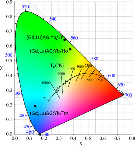
UC luminescence is an anti-Stokes process in which a longer wavelength radiation, usually near infrared (NIR) or IR light, is converted to a shorter wavelength such as UV or visible light via a two-photon or multi-photon mechanism [Citation79]. The materials are drawing wide interest since they can be used as biological labels for medical diagnosis and therapy, in photovoltaic cells to efficiently harvest solar energy, and also in laser and anti-counterfeit fields [Citation79]. The activators used for UC are those that usually do not exhibit efficient DC luminescence, including Pr3+, Sm3+, Ho3+, Er3+, and Tm3+. Though when properly doped in a host the above activators themselves have been able to produce UC emission, the efficiency is usually rather limited owing to their unsatisfactory NIR/IR excitations. Yb3+ is thus widely employed as a codopant to improve NIR absorption (at ∼980 nm, the 2F7/2 → 2F5/2 Yb3+ transition) and to sensitize UC emission via nonradiative energy transfer from Yb3+ to the activator. The most preferred and widely used hosts for UC luminescence are fluorides owing to their low phonon energy, though other material types, such as Y2O3 transparent ceramics [Citation80, Citation81] and Gd2O2S powder [Citation82], were also explored. YAG was suggested to possess a large ground-state Stark splitting and has a quasi three-level energy structure, which may enable a broad and intense absorption of Yb3+ in it [Citation83]. The energy transferred from Yb3+ may effectively populate the upper level of Tm3+ in YAG [Citation83]. UC performances were recently studied for stabilized GAG with the compositions of [(Gd1-xLux)0.948Yb0.05Ln0.002]AG (x = 0.1–0.5, Ln = Er, Ho, and Tm) [Citation53, Citation84, Citation85]. Despite the dilute Yb and Ln concentrations, strong UC luminescence was clearly observed in each case upon laser exciting Yb3+ at 978 nm, as shown in figure together with the mechanism of UC. The UC luminescence presents as an intense blue band at ∼487 nm (1G4 → 3H6 transition) and a weaker red one at ∼650 nm (1G4 → 3F4) for Tm3+, as a fairly strong green band at 543 nm (5F4,5S2 → 5I8) and a strong red band at 668 nm (5F5 → 5I8) for Ho3+, and as three bands at 525 nm (green, 2H11/2 → 4I15/2), 556 nm (yellow, 4S3/2 → 4I15/2) and 655 nm (red, 4F9/2 → 4I15/2) for Er3+. CIE chromaticity coordinates of the UC luminescence were found to be around (0.14, 0.19) for Tm3+, (0.38, 0.58) for Ho3+, and (0.34, 0.64) for Er3+, corresponding to blue, greenish yellow, and green colors, respectively (figure ). Lowered luminescence with increasing Lu incorporation and enhanced emission with increasing temperature of phosphor synthesis were found for the above UC systems. Analyzing the emission intensity against excitation power indicated that the UC luminescence may have occurred via a three-photon process for Tm3+ and a two-photon process for both Ho3+ and Er3+, which are schematically shown in the right part of figure [Citation53, Citation84, Citation85].
Figure 18. Up-conversion (UC) luminescence spectra of the Yb/Ho, Yb/Er, and Yb/Tm codoped (Gd1−xLux)AG solid solutions. Mechanisms of the UC processes are presented in the right-hand schemes. Reproduced with permission from [Citation85], copyright 2014 by Trans Tech Publications, and [Citation84], copyright 2014 by Elsevier.
![Figure 18. Up-conversion (UC) luminescence spectra of the Yb/Ho, Yb/Er, and Yb/Tm codoped (Gd1−xLux)AG solid solutions. Mechanisms of the UC processes are presented in the right-hand schemes. Reproduced with permission from [Citation85], copyright 2014 by Trans Tech Publications, and [Citation84], copyright 2014 by Elsevier.](/cms/asset/6a97c7dd-0dd5-41b7-a84b-8c94312d748a/tsta_a_11661245_f0018_oc.jpg)
Figure 19. Color coordinates for the UC luminescence of (Gd, Lu)AG:Yb/Ln (Ln = Er, Ho, and Tm).
5. Single-crystal and transparent-ceramic scintillators based on GAG
A scintillator is essentially a luminescent material that absorbs high-energy photons and then emits visible light, for which efficient absorption of the excitation source is a fundamental requirement [Citation41, Citation86]. Since the relation among absorption coefficient (ηabs), theoretical density (ρ), and effective atomic number (Zeff) can be expressed as ηabs = ρZeff4 [Citation87], high theoretical density (generally >6 g cm−3) and particularly high effective atomic number are thus needed for an excellent scintillator, though other characteristics such as high light yield and fast response (10–100 ns, dominant decay generally <3 μs to avoid signal pile-up with standard shaping electronics) are also essential [Citation86]. Scintillators combined with photodetectors are widely used in various medical imaging technologies, such as x-ray computed tomography, positron emission tomography (PET), and single-photon emission computed tomography (SPECT), and also in high energy and nuclear physics. The most common scintillators up to date are CsI:Tl, CdWO4, and Bi4Ge3O12 (BGO) single crystals, but they have their respective shortcomings such as hygroscopicity, poor machinability, insufficient light output, and slow blinking [Citation86]. For these reasons, Ce-doped silicates, such as Gd2SiO5 (GSO), Lu2SiO5 (LSO), (Lu1−xYx)2SiO5 (LYSO), and LaBr3 are being developed as alternatives [Citation88–Citation94].
GAG-based single crystal scintillators are mostly studied by Kamada et al [Citation24, Citation25, Citation95–Citation97] through crystal growth by the μ-PD and CZ techniques. The CZ-grown Gd3(Al2Ga3)O12:1 at%Ce single crystal, where Ga3+ is a lattice stabilizer, was reported to have a high light yield of 46 000 photons/MeV for the Ce3+ emission (31 000 photons/MeV for LYSO:Ce), an energy resolution of 4.9% at 662 keV, a primary decay time of 88 ns (91%), and a high theoretical density of 6.63 g cm−3 [Citation24]. The crystals are thus regarded as promising scintillators for PET, SPECT, and gamma camera. The μ-PD grown Gd3(Al5−xGax)O12:1 at%Pr single crystals (x = 1–5) were found to exhibit the 5d → 4f and intra-4f2 transition emissions of Pr3+ in the 300–400 and 480–600 nm (dominant) regions, respectively, together with the intra-4f7 Gd3+ emission at 310 nm (figure ) [Citation25]. A higher Ga3+ content would suppress the 5d → 4f Pr3+ emission while enhance the f–f transitions of both Gd3+ and Pr3+. A low light output of ∼4500 photons/MeV, only about 1/5 of the CZ-grown LuAG:Pr standard, and a relatively long primary decay time of 214 ns (98.8%) were reported for the Gd3(Al2Ga3)O12:1 at%Pr single crystal [Citation25]. The poor light output was suggested to be associated with an energy transfer from the 5d state of Pr3+ to the 4f state of Gd3+ and non-radiative relaxations from the 5d to 4f states of Pr3+, with the former being dominant, as schematically shown in figure [Citation98]. Pr3+ was thus suggested not to be a proper activator for Gd3+-containing scintillators. By simultaneously modifying GAG with Lu3+ for Gd3+ and Ga3+ for Al3+, (Gd2Lu1)(Al5−xGax)O12:Ce single crystals (x = 1–5; Ce3+ content: 0.2, 1.0, and 3 at%) were grown by the μ-PD technique and thoroughly investigated for their luminescence properties [Citation95]. It was shown that decay of the 5d → 4f Ce3+ emission at ∼520 nm accelerates with increasing Ga or Ce concentration, and the best composition of (Gd2Lu1)(Al2Ga3)O12:1 at%Ce has a light yield of ∼22 000 photons/MeV, about 70% of LYSO:Ce (31 000 photons/MeV), a theoretical density of 6.88 g cm−3, and a decay time of 76.5 ns (83%) and 282 ns (17%). With the combinatorial approach, Kamada et al made comprehensive composition optimization for 0.2 at% Ce3+ doped (Gd3−xLux)(Al5−yGay)O12 [Citation96] and (Gd3−xYx)(Al5−yGay)O12 [Citation97] single crystals. The light output of Ce3+ in the best hosts of (Gd2Y1)(Al2Ga3)O12 and Gd3(Al2Ga3)O12 reached ∼42 000–44 000 photons/MeV, being ∼150% of the value of LYSO:Ce and 730% of that of BGO (5700 photons/MeV), with the scintillation decay time dominated by 50–80 ns. The energy resolution at 662 kV was determined to be 8.3% [Citation96], which, though inferior to the 6.7% for high-quality CZ-grown LuAG:Ce, is comparable to the 8.7% measured for LYSO:Ce. Bandgap engineering was pointed out to be crucial in developing high quality scintillators, as also suggested by previous studies. For example, the 5d → 4f luminescence of Ce3+ is quenched in the high density garnets of Lu3Ga5O12 (7.4 g cm−3) and Gd3Ga5O12 (7.04 g cm−3) owing to positioning of the Ce3+ 5d states in the conduction band of the host [Citation99], and the performance of LuAG:Ce is strongly degraded by shallow electron traps (LuAl anti-site defects) via delaying energy transfer to Ce3+ and giving rise to quite slow components in the scintillation response [Citation100, Citation101]. A balanced Ga and Gd admixture may eliminate the trapping effects by burying the shallow traps in the bottom of the conduction band and at the same time avoid ionization of the Ce3+ activators by separating the 5d excited level from the conduction band, as schematically shown in figure [Citation96, Citation97].
Figure 20. Radioluminescence spectra of the Gd3(Al5−xGax)O12:1 at%Pr single crystals under γ-ray excitations. Reproduced with permission from [Citation25], copyright 2012 by Elsevier.
![Figure 20. Radioluminescence spectra of the Gd3(Al5−xGax)O12:1 at%Pr single crystals under γ-ray excitations. Reproduced with permission from [Citation25], copyright 2012 by Elsevier.](/cms/asset/2355586c-2b5f-4968-bfa2-11df632de452/tsta_a_11661245_f0020_ob.jpg)
Figure 21. Energy diagram for the Gd3+ and Pr3+ centers in (GdxLu3−x)(Ga3Al2)O12 (x < 0.2), with the energy transfer channel from Pr3+ to Gd3+ indicated. The right-hand scheme depicts non-radiative relaxation from the lowest 5d1 to low-lying 3P0 and 1D2 levels of Pr3+. Reproduced with permission from [Citation98], copyright 2013 by Elsevier B V.
![Figure 21. Energy diagram for the Gd3+ and Pr3+ centers in (GdxLu3−x)(Ga3Al2)O12 (x < 0.2), with the energy transfer channel from Pr3+ to Gd3+ indicated. The right-hand scheme depicts non-radiative relaxation from the lowest 5d1 to low-lying 3P0 and 1D2 levels of Pr3+. Reproduced with permission from [Citation98], copyright 2013 by Elsevier B V.](/cms/asset/88d9c4d5-50e4-4d85-b612-65ea843955fc/tsta_a_11661245_f0021_oc.jpg)
Figure 22. Energy level scheme showing bandgap and 5d1 level engineering for the (Gd, Lu)3(Ga, Al)5O12:Ce scintillation crystals. The Ga component helps to lower the conduction band (CB) to bury the shallow traps while the Gd component pushes away the 5d1 level of Ce3+ from the bottom of CB to avoid Ce3+ ionization. Reproduced with permission from [Citation96], copyright 2011 by the American Chemical Society.
![Figure 22. Energy level scheme showing bandgap and 5d1 level engineering for the (Gd, Lu)3(Ga, Al)5O12:Ce scintillation crystals. The Ga component helps to lower the conduction band (CB) to bury the shallow traps while the Gd component pushes away the 5d1 level of Ce3+ from the bottom of CB to avoid Ce3+ ionization. Reproduced with permission from [Citation96], copyright 2011 by the American Chemical Society.](/cms/asset/c8adae69-4f2b-41a3-8fe9-e41aacd72389/tsta_a_11661245_f0022_oc.jpg)
Aside from single crystals, transparent ceramics are under active development for scintillation applications, since the sintering technique generally has advantages in product size and fabrication cost. The (Y,Gd)2O3:Eu transparent ceramic (inline transmittance ∼73% at the 610 nm emission of Eu3+ or ∼90% of the theoretical value, figure ), fabricated via pressureless sintering, pressureless sintering plus hot isostatic pressing, and vacuum hot pressing, has been the first commercialized polycrystalline scintillator used in medical x-ray detectors [Citation41, Citation86]. The (Y0.67Gd0.30Eu0.03)2O3 composition (5.92 g cm−3) was reported to have a relative light output 2.5 times higher and ∼30% lower than those of CdWO3 and CsI:Tl single crystals, respectively [Citation41]. Li et al [Citation102] fabricated transparent (Y0.3Gd0.67Eu0.03)2O3 ceramic with a higher Gd content, an inline transmittance of ~68% at the 610 nm Eu3+ emission and a higher theoretical density of 6.87 g cm−3, by vacuum sintering at 1670 °C for 2 h of the oxide powders calcined from coprecipitated carbonate precursors. The main problem associated with Eu3+ emission is the long fluorescence decay, which is usually ∼1 ms [Citation41, Citation86]. Yanagida et al [Citation8, Citation103] made transparent YAG:Ce and (Gd,Y)AG:Ce ceramics for possible scintillation applications (the Gd content and optical transmittance not specified), and the dominant decay time was found to be ∼90 ns under γ-ray excitations. Light yield of the latter was reported to be 30% of the former, without specifying the reason, and the energy resolution was found to be ∼8% at 662 keV when coupled with an avalanche photodiode [Citation103]. The stopping power of (Gd, Y)AG:Ce was reported to be five times as high as that of YAG:Ce [Citation103]. Li et al [Citation104] studied sintering of (Y1−xGdx)AG:Ce (x = 0.01, 0.5, 0.75, and 1; Ce content: 2 at%) transparent ceramics with commercially available nano-sized powders. It was shown that the GAG composition (x = 1.0) cracks owing to the stress (volume change) arising from thermal decomposition while all the other compositions can be densified to transparency by vacuum sintering at 1600–1700 °C for 5 h. The (Y1.48Gd1.5Ce0.02)AG ceramic, with an inline transmittance of ∼65% at 800 nm, exhibits Ce3+ emission at ∼570 nm under 340 nm UV excitation, which is red-shifted ∼40 nm relative to YAG:Ce (∼530 nm) owing to the high content of less electronegative Gd3+ (figure ). Cherepy et al [Citation105] studied radioluminescence properties of translucent (Tb3−xCex)AG ceramics (figure ), and much higher light yields (80 000 photons/MeV) than LuAG:Ce (∼30 000 photons/MeV) were found under β-ray excitations. The decay, however, is slow owing to energy migration on the Tb3+ sites, and the principal decay time reaches <1 μs only at the high Ce3+ content of x = 0.12. By applying vacuum sintering plus hot isostatic pressing, Cherepy et al [Citation105] also fabricated a series of GAG-based scintillation ceramics (Ce3+ content: 3 at%), including (Gd1.5Y1.5)3Al5O12 (GYAG), (Gd1.5Y1.5)3(Al5−xScx)O12 (GYSAG), and Gd3(Al3Sc2)O12 (GSAG), using Y3+/Sc3+ as dopant for lattice stabilization (figure ). GYAG:Ce was reported to have a very high light yield of ∼100 000 photons/MeV under β-ray excitation, due to an efficient energy transfer from Gd3+, and have decay time in the 100–200 ns range. Transparency, however, was not achieved for this composition due to the presence of a small amount of GdAlO3 secondary phase. In contrast, GSAG and GYSAG only produced the moderate light yields of ∼20 000 photons/MeV, with the primary decay time <200 ns, but formed phase-pure garnet with excellent transparency for the former and acceptable transparency for the latter (x ≥ 0.12, transmittance data not shown). In general, the Ce3+ emission in Gd-containing scintillators simultaneously has fast primary decay (<200 ns) and high light yield, as compared from table for the typical garnet compounds discussed in this work, showing substantial advantages of the GAG host lattice.
Figure 23. Transmittance and luminescence (excitation: 254 nm UV light) spectra of a 1.5 mm thick (Y0.67Gd0.30Eu0.03)2O3 ceramic scintillator. Reproduced with permission from [Citation86], copyright 1997 by Annual Reviews Inc.
![Figure 23. Transmittance and luminescence (excitation: 254 nm UV light) spectra of a 1.5 mm thick (Y0.67Gd0.30Eu0.03)2O3 ceramic scintillator. Reproduced with permission from [Citation86], copyright 1997 by Annual Reviews Inc.](/cms/asset/0ab605bb-e603-45fe-824f-b509622f7af7/tsta_a_11661245_f0023_ob.jpg)
Figure 24. In-line transmittance and luminescence (excitation: 340 nm UV light) spectra of a 1.3 mm thick (Y1.48Gd1.5Ce0.02)AG scintillation ceramic. Reproduced with permission from [Citation104], copyright 2010 by the American Ceramic Society.
![Figure 24. In-line transmittance and luminescence (excitation: 340 nm UV light) spectra of a 1.3 mm thick (Y1.48Gd1.5Ce0.02)AG scintillation ceramic. Reproduced with permission from [Citation104], copyright 2010 by the American Ceramic Society.](/cms/asset/a442a7ec-757a-4fb5-bb1c-d4a60187b248/tsta_a_11661245_f0024_oc.jpg)
Figure 25. Beta-excited radioluminescence spectra and appearances of the Ce3+ doped TAG and LuAG ceramics with scatter mean free path >1 cm. Reproduced with permission from [Citation105], copyright 2009 by IEEE.
![Figure 25. Beta-excited radioluminescence spectra and appearances of the Ce3+ doped TAG and LuAG ceramics with scatter mean free path >1 cm. Reproduced with permission from [Citation105], copyright 2009 by IEEE.](/cms/asset/d322dffa-a6ad-4a9e-ad45-fd28a57cd07c/tsta_a_11661245_f0025_oc.jpg)
Figure 26. Beta-excited radioluminescence spectra and appearances of the Ce3+ doped gadolinium-based garnet ceramics. Reproduced with permission from [Citation105], copyright 2009 by IEEE.
![Figure 26. Beta-excited radioluminescence spectra and appearances of the Ce3+ doped gadolinium-based garnet ceramics. Reproduced with permission from [Citation105], copyright 2009 by IEEE.](/cms/asset/13040eef-cddf-418a-86df-8babb7e5e2fb/tsta_a_11661245_f0026_oc.jpg)
Table 1. A summary of the scintillation properties of the promising single-crystal/ceramic scintillators discussed in this work.
6. Summary and outlook
Lattice stabilization of GAG (Gd3Al5O12, GAG) and the related development of advanced optical materials are summarized in this article, including down-/up-conversion phosphors, transparent ceramics, and single crystals. It is shown that novel emission features and significantly improved luminescence can be achieved for a number of phosphor systems with the more covalent GAG lattice and the efficient energy transfer from Gd3+ to the activator. GAG-based single crystals and transparent ceramics with Ce3+ as the activator are shown to have fast scintillation decay and high light yields, and thus hold great potential as scintillators for a wide range of applications. Anti-site defects commonly exist in aluminate garnets [Citation106–Citation108], and their occurrence and energy level have profound influences on various aspects of emission through interacting with the excited electrons. These issues, however, have rarely been tackled for the GAG-based garnets, either when Lu3+ or Ga3+ is used as lattice stabilizer, and thus need to clarify in future studies for a better control of optical properties. In addition, GAG-based transparent ceramics have been much less developed than their YAG and LuAG counterparts, and need significantly more studies on powder processing and sintering technologies to improve their overall transmittance and other optical performances.
Acknowledgment
Experimental contribution to GAG-based phosphors by Dr Jinkai Li, through his PhD thesis work under the supervision of Dr Ji-Guang Li, is acknowledged. Sincere thanks are due to the editorial board of STAM for inviting this review.
References
- XuY-NChingW Y 1999 Phys. Rev. B 59 10530 10.1103/PhysRevB.59.10530
- GeusicG ENarcosH MVan UitertL G 1964 Appl. Phys. Lett. 4 182 10.1063/1.1753928
- IkesueAKonoshitaTKamataKYoshidaK 1995 J. Am. Ceram. Soc. 78 1033 10.1111/j.1151-2916.1995.tb08433.x
- IkesueAAungY L 2006 J. Am. Ceram. Soc. 89 1936 10.1111/j.1551-2916.2006.01043.x
- FornasieroLMixEPetersVPetermannKHuberG 2000 Ceram. Int. 26 589 10.1016/S0272-8842(99)00101-7
- NishiuraSTanabeSFujiokaKFujimotoY 2011 IOP Conf. Ser.: Mater. Sci. Eng. 18 102005 10.1088/1757-899X/18/10/102005
- BachmannVRondaCMeijerinkA 2009 Chem. Mater. 21 2077 10.1021/cm8030768
- YanagidaT 2005 IEEE Trans. Nucl. Sci. 52 1836 10.1109/TNS.2005.856757
- MizunoMYamadaTNoguchiT 1977 Yogyo-Kyokai-Shi 85 30 10.2109/jcersj1950.85.30
- MizunoMYamadaTNoguchiT 1977 Yogyo-Kyokai-Shi 85 90 10.2109/jcersj1950.85.30
- MizunoMYamadaTNoguchiT 1977 Yogyo-Kyokai-Shi 85 374 10.2109/jcersj1950.85.30
- MizunoMYamadaTNoguchiT 1977 Yogyo-Kyokai-Shi 85 543 10.2109/jcersj1950.85.30
- MizunoMYamadaTNoguchiT 1978 Yogyo-Kyokai-Shi 86 360 10.2109/jcersj1950.86.996_359
- Van UitertL GGrodkiewiczW HDearbornE F 1965 J. Am. Ceram. Soc. 48 105 10.1111/j.1151-2916.1965.tb11809.x
- ManabeTEgashiraK 1971 Mater. Res. Bull. 6 1167 10.1016/0025-5408(71)90052-3
- ShishidoTOkamuraKYajimaS 1978 J. Am. Ceram. Soc. 61 373 10.1111/j.1151-2916.1978.tb09337.x
- LiJ KLiJ-GZhangZ JWuX LLiuS HLiX DSunX DSakkaY 2012 J. Am. Ceram. Soc. 95 931
- ChaudhurySParidaS CPillaiK TMudherK D S 2007 J. Solid State Chem. 180 2393 10.1016/j.jssc.2007.06.003
- LiJ-GLiX DSunX DIshigakiT 2008 J. Phys. Chem. C 112 11707 10.1021/jp802383a
- LiY HHongG Y 2007 J. Lumin. 124 297 10.1016/j.jlumin.2006.03.016
- WuX LLiJ-GZhuQLiJ KMaR ZSasakiTLiX DSunX DSakkaY 2012 Dalton Trans. 41 1854 10.1039/c1dt11332a
- WuX LLiJ-GPingD-HLiJ KZhuQLiX DSunX DSakkaY 2013 J. Alloys Compd. 559 188 10.1016/j.jallcom.2013.01.072
- ChiangC-CTsaiM-SHonM-H 2007 J. Electrochem. Soc. 154 J326 10.1149/1.2768900
- KamadaKYanagidaTEndoTTsutumiKUsukiYNiklMFujimotoYFukaboriAYoshikawaA 2012 J. Cryst. Growth 352 88 10.1016/j.jcrysgro.2011.11.085
- KamadaKYanagidaTPejchalJNiklMEndoTTsutumiKUsukiYFujimotoYFukaboriAYoshikawaA 2012 J. Cryst. Growth 352 84 10.1016/j.jcrysgro.2011.11.085
- MagliaFBuscagliaVGennariSGhignaPDapiaggiMSpeghiniABettinelliM 2006 J. Phys. Chem. B 110 6561 10.1021/jp055713o
- TomikiTIsaYKadekawaYGanahaYToyokawaNMiyazatoTMiyazatoMKohatsuTShimabukuroHTamashiroJ 1996 J. Phys. Soc. Japan 65 1106 10.1143/JPSJ.65.1106
- ZorenkoYGorbenkoVVoznyakTBatentschukMOsvetAWinnackerA 2008 J. Lumin. 128 652 10.1016/j.jlumin.2007.11.069
- ZorenkoYGorbenkoVVoznyakTZorenkoTKuklinskiBTuros-MatysyakRGrinbergM 2009 Opt. Spectrosc. 106 365 10.1134/S0030400X09030102
- BiJLiJ-GGuanW MChenJ LSunXD 2014 Key Eng. Mater. 1028 10.4028/www.scientific.net/KEM.602-603.1028
- LiJ KLiJ-GZhangZ JWuX LLiuS HLiX DSunX DSakkaY 2012 Sci. Technol. Adv. Mater. 13 035007 10.1088/1468-6996/13/3/035007
- LiJ KLiJ-GLiuS HLiX DSunX DSakkaY 2013 Sci. Technol. Adv. Mater. 14 054201 10.1088/1468-6996/14/5/054201
- LiJ KLiJ-GWuX LLiuS HLiX DSunX D 2013 Key Eng. Mater. 544 245 10.4028/www.scientific.net/KEM.544.245
- RavichandranDRoyRChakhovskoiA GHuntC EWhiteW BErdeiS 1997 J. Lumin. 71 291 10.1016/S0022-2313(96)00137-8
- PereiraP F SCaiutJ M ARibeiroS J LMessaddeqYCiuffiKJRochaL AMolinaE FNassarE J 2007 J. Lumin. 126 378 10.1016/j.jlumin.2006.08.085
- ZhuQLiJ-GZhiCMaRSasakiTXuJ XLiuC HLiX DSunX DSakkaY 2011 J. Mater. Chem. 21 6903 10.1039/c1jm00048a
- ZhuQLiJ-GLiX DSunX DYangQZhuM YSakkaY 2014 Sci. Technol. Adv. Mater. 15 014203 10.1088/1468-6996/15/1/014203
- LuBLiJ-GSakkaY 2013 Sci. Technol. Adv. Mater. 14 064202 10.1088/1468-6996/14/6/064202
- WangX JLiJ-GZhuQLiX DSunX DSakkaY 2014 Sci. Technol. Adv. Mater. 15 014204 10.1088/1468-6996/15/1/014204
- LiJ KLiJ-GLiJLiuS HLiX DSunX DSakkaY 2013 J. Solid State Chem. 206 104 10.1016/j.jssc.2013.08.003
- GreskovichC DCusanoDHoffmanDRiednerR J 1992 Am. Ceram. Soc. Bull. 71 1120
- MatijevićEHsuW P 1987 J. Colloid Interface Sci. 118 506 10.1016/0021-9797(87)90486-3
- HsuW PRönnquistLMatijevićE 1988 Langmuir 4 31 10.1021/la00079a005
- AikenBHsuW PMatijevićE 1988 J. Am. Ceram. Soc. 71 845 10.1111/j.1151-2916.1988.tb07534.x
- MatijevićE. 1993 Chem. Mater. 5 412 10.1021/cm00028a004
- LiJ-GLiX DSunX DIkegamiTIshigakiT 2008 Chem. Mater. 20 2274 10.1021/cm7033257
- ZhuQLiJ-GLiX DSunX DSakkaY 2011 Sci. Technol. Adv. Mater. 12 055001 10.1088/1468-6996/12/5/055001
- LiJ-GZhuQLiX DSunX DSakkaY 2011 Acta Mater. 59 3688 10.1016/j.actamat.2011.03.004
- SordeletD JAkincMPanchulaM LHanYHanM H 1994 J. Eur. Ceram. Soc. 14 123 10.1016/0955-2219(94)90100-7
- MatsushitaNTsuchiyaNNakatsukaKYanagitaniT 1999 J. Am. Ceram. Soc. 82 1977
- HuiYSunX DChenJ LLiX DHuoDLiuS HZhuQZhangMLiJ-G 2014 IEEE Trans. Nucl. Sci. 61 362 10.1109/TNS.2013.2286999
- XuX JSunX DLiuHLiJ-GLiX DHuoDLiuS H 2012 J. Am. Ceram. Soc. 95 3821 10.1111/jace.12046
- LiJ K 2013 Crystal structure stabilization of gadolinium aluminate garnet (Gd3Al5O12) and development of new phosphors PhD Thesis Northeastern University
- ZhuQLiJ-GMaR ZSasakiTYangX JLiX DSunX DSakkaY 2012 J. Solid State Chem. 192 229 10.1016/j.jssc.2012.04.015
- GeorgeN CDenaultK ASeshadriR 2013 Annu. Rev. Mater. Res. 43 481 10.1146/annurev-matsci-073012-125702
- ShaoQLiHGongYJiangJLiangCHeJ 2010 J. Alloys Compound. 498 199 10.1016/j.jallcom.2010.03.159
- WangX JZhouG HZhangH LLiH LZhangZ JSunZ 2012 J. Alloys Compd. 519 149 10.1016/j.jallcom.2011.12.158
- KatelnikovasABettentrupHUhlichDSakirzanovasSüstelT JKareivaA 2009 J. Lumin. 129 1356 10.1016/j.jlumin.2009.07.006
- ManiquizM CJungK YJeongS M 2010 J. Electrochem. Soc. 157 H1135 10.1149/1.3503569
- HipolitoM GOcampoA CFregosoO AMartinezEMendozaJ GFalconyC 2004 Phys. Status Solidi a 201 72 10.1002/pssa.200306692
- ChoeJ YRavichandranDBlomquistS MMortonD CKirchnerK WErvinM HLeeU 2001 Appl. Phys. Lett. 78 3800 10.1063/1.1378313
- HakutaYSeinoKUraHAdschiriTTakizawaHAraiK 1999 J. Mater. Chem. 9 2671 10.1039/a903074c
- GuoKHuangM-LChenH-HYangX-XZhaoJ-T 2012 J. Non-Cryst. Solids 358 88 10.1016/j.jnoncrysol.2011.08.032
- DiekeG HCrosswhiteH M 1963 Appl. Opt. 2 675 10.1364/AO.2.000675
- WeghR TMeijerinkALamminmakiR JHolsaJ 2000 J. Lumin. 87-89 1002 10.1016/S0022-2313(99)00506-2
- PeijzelP SMeijerinkAWeghR TReidM FBurdickG W 2005 J. Solid State Chem. 178 448 10.1016/j.jssc.2004.07.046
- SongH WWangJ W 2006 J. Lumin. 118 220 10.1016/j.jlumin.2005.08.016
- RatinenH 1972 Phys. Solid State A 12 447 10.1002/pssa.2210120211
- KlimczakMMalinowskiMSarneckiJPiramidowiczR 2009 J. Lumin. 129 1869 10.1016/j.jlumin.2009.04.073
- HeyesA LSeefeldtSFeistJ P 2006 Opt. Laser Technol. 38 257 10.1016/j.optlastec.2005.06.012
- WangHYangJZhangC MLinJ 2009 J. Solid State Chem. 182 2716 10.1016/j.jssc.2009.07.033
- YangJLiCQuanZZhangCYangPLiYYuCLinJ 2008 J. Phys. Chem. C 112 12777 10.1021/jp803945w
- ZhuQLiJ-GLiX DSunX D 2009 Acta Mater. 57 5975 10.1016/j.actamat.2009.08.026
- LiJ KLiJ-GLiuS HLiX DSunX DSakkaY 2013 J. Mater. Chem. C 1 7614 10.1039/c3tc31413h
- DiW HShirahataNZengH BSakkaY 2010 Nanotechnology 21 365501
- DorenbosP 2002 J. Alloys Compound. 341 156 10.1016/S0925-8388(02)00056-7
- DiWWangXZhuPChenB 2007 J. Solid State Chem. 180 467 10.1016/j.jssc.2006.11.006
- WuX LLiJ-GLiJ KZhuQLiX DSunX DSakkaY 2013 Sci. Technol. Adv. Mater. 14 015006 10.1088/1468-6996/14/1/015006
- AzuelF 2004 Chem. Rev. 104 139 10.1021/cr020357g
- HinklinT RRandS CLaineR M 2008 Adv. Mater. 20 1270 10.1002/adma.200701235
- HouX RZhouS MJiaT TLinHTengH 2011 Phys.: Condens. Matter 406 3931 10.1016/j.physb.2010.10.090
- Martin-RodriguezRFischerSIvaturiAFroehlichBKramerK WGoldschmidtJ CRichardsB SMeijerinkA 2013 Chem. Mater. 25 1912 10.1021/cm4005745
- XuX DWuFXuW WZongY HWangX DZhaoZ WZhouG QXuJ 2008 J. Alloys Compound. 462 347 10.1016/j.jallcom.2007.08.053
- LiJ KLiJ-GLiJLiuS HLiX DSunX DSakkaY 2014 J. Alloys Compound. 582 623 10.1016/j.jallcom.2013.08.082
- LiJ KLiJ-GLiuS HLiX DSunX DSakkaY 2014 Key Eng. Mater. 602-603 1034 10.4028/www.scientific.net/KEM.602-603.1034
- GreskovichCDuclosS 1997 Annu. Rev. Mater. Sci. 27 69 10.1146/annurev.matsci.27.1.69
- ZorenkoYGorbenkoVKonstantkevychIGrinevBGlobusM 2002 Nucl. Instrum. Methods Phys. Res. A 486 309 10.1016/S0168-9002(02)00725-8
- NiklM 2006 Meas. Sci. Technol. 17 R37 10.1088/0957-0233/17/4/R01
- SuzukiHTombrelloT AMelcherC LSchweitzerJ S 1922 Nucl. Instrum. Methods Phys. Res. A 320 263 10.1016/0168-9002(92)90784-2
- CookeD WMcClellanK JBennettB LRoperJ MWhittakerM TMuenchausenR ESzeR C 2000 J. Appl. Phys. 88 7360 10.1063/1.1328775
- PauwelsDLe MassonNVianaBKahn-HarariAvan LoefE V DDorenbosPvan EijkC W E 2000 IEEE Trans. Nucl. Sci. 47 1787 10.1109/23.914446
- KawamuraSHiguchiMKanekoJ HNishiyamaSHarunaJSaekiSUedaSKurashigeHIshibashiHFurusakaM. 2009 Cryst. Growth Des. 9 1470 10.1021/cg800932b
- KramerK WDorenbosPGudelH Uvan EijkC W E 2006 J. Mater. Chem. 6 2773 10.1039/b602762h
- ChenHYangPZhouCJiangCPanJ 2006 Cryst. Growth Des. 6 809 10.1021/cg050358c
- KamadaKYanagidaTPejchalJNiklMEndoTTsutumiKUsukiYFujimotoYFukaboriAYoshikawaA 2012 J. Cryst. Growth 352 35 10.1016/j.jcrysgro.2011.11.085
- KamadaKEndoTTsutumiK 2011 Cryst. Growth Des. 11 4484 10.1021/cg200694a
- KamadaKYanagidaTPejchalJNiklMEndoTTsutumiKFujimotoYFukaboriAYoshikawaA 2011 J. Phys. D: Appl. Phys. 44 505104 10.1088/0022-3727/44/50/505104
- WuY TRenG H 2013 Opt. Mater. 35 2146 10.1016/j.optmat.2013.05.039
- RaukasMBasunS Avan SchaikWYenW MHappekU 1996 Appl. Phys. Lett. 69 3300 10.1063/1.117286
- NiklMVeddaAFasoliMFontanaILagutaV VMihokovaEPejchalJRosaJNejezchlebK 2007 Phys. Rev. B 76 195121 10.1103/PhysRevB.76.195121
- ChewpraditkulWSwiderskiLMoszynskiMSzczesniakTSyntfeld-KazuchAWanarakCLimsumanP 2009 IEEE Trans. Nucl. Sci. 56 3800 10.1109/TNS.2009.2033994
- LiX DSunX DLiJ-GXiuZ MGaoTLiuY NHuX Z 2010 Int. J. Appl. Ceram. Technol. 7 E1 10.1111/j.1744-7402.2008.02351.x
- YanagidaT 2007 Nucl. Instrum. Methods Phys. Res. A 579 23 10.1016/j.nima.2007.04.173
- LiX DLiJ-GXiuZ MHuoDSunX D 2010 J. Am. Ceram. Soc. 93 2229 10.1111/j.1551-2916.2010.03726.x
- CherepyN J 2009 IEEE Trans. Nucl. Sci. 56 873 10.1109/TNS.2009.2020165
- Munoz-GarciaA BArtachoESeijoL 2009 Phys. Rev. B 80 014105 10.1103/PhysRevB.80.014105
- ZorenkoYVoznyakTGorbenkoV VDoroshenkoATolmachevAYavetskiyRPetrushaITurkevichV 2013 Opt. Mater. 35 2049 10.1016/j.optmat.2012.07.009
- HavenDTDickensP TWeberM HLynnK G 2013 J. Appl. Phys. 114 043102 10.1063/1.4816260