
Abstract
Since most starting materials for tissue engineering are in powder form, using powder-based additive manufacturing methods is attractive and practical. The principal point of employing additive manufacturing (AM) systems is to fabricate parts with arbitrary geometrical complexity with relatively minimal tooling cost and time. Selective laser sintering (SLS) and inkjet 3D printing (3DP) are two powerful and versatile AM techniques which are applicable to powder-based material systems. Hence, the latest state of knowledge available on the use of AM powder-based techniques in tissue engineering and their effect on mechanical and biological properties of fabricated tissues and scaffolds must be updated. Determining the effective setup of parameters, developing improved biocompatible/bioactive materials, and improving the mechanical/biological properties of laser sintered and 3D printed tissues are the three main concerns which have been investigated in this article.
1. Introduction
Additive manufacturing (AM) is a technique for fabricating parts in precise geometry using computer aided design (CAD) and computer aided manufacturing (CAM) [Citation1]. In each AM technique, the 3D model designed in CAD software is converted to STL format, which is a triangular mesh of the object, and then the STL format is sliced into 2D profile layers. Each sliced layer of the model is bonded to the previous layer on the build platform until a 3D part is fabricated. The principal AM technologies are selective laser sintering (SLS), stereolithography (SLA), fused deposition modeling (FDM), direct metal laser sintering (DMLS), and inkjet 3D printing (3DP) techniques [Citation2, Citation3]. Depending on the process and materials used, each technique has both strong and weak points. The most significant elements that should be considered in choosing an appropriate AM technology for a particular purpose are accuracy, time, and cost of fabrication. The parameter of accuracy refers to the thickness of the layers and the system of consolidation, and since AM techniques are tool-free fabrication methods, time of production can outweigh increased fabrication costs per item [Citation3, Citation4].
Biomedical applications, e.g., tissues, scaffolds, and fixation devices, have specific aspects of fabrication which should be considered. For biomedical applications, the use of these AM methods without rigid support structures is strongly recommended [Citation5]. In supportless AM methods the imprinted powders surround and support complex parts during the printing process, and after finishing the process, users can reuse all uncured support powders. Other additive processes require the building of solid support structures to support complex geometries during the printing process. Users have to discard these support structures after use, and the wasted material contributes significantly to the cost of additive technologies. In addition, removing attached supports from fabricated parts limits the ability to stack or nest parts [Citation6].
AM approaches, particularly 3DP and SLS, are simple and adaptable to using a broad range of powders to produce porous ceramics, polymers, and metal-based tissues [Citation7, Citation8]. To enhance bone regeneration in fabricated tissues, using powder-based AM techniques is recommended. These kinds of fabricated scaffolds can be filled with a porous spacer, allowing the ingrowth of a blood vessel [Citation9].
In this article, the working principle of SLS and inkjet 3DP and modifications of these methods are reviewed. Materials used in SLS and inkjet 3DP and optimization of the effective parameters of these two powder-based AM techniques for the fabrication of useful bone tissues and scaffolds are highlighted. Biological tests (in vitro, in vivo and apatite layer formation) conducted on the fabricated tissues and scaffolds are presented and discussed, as well as clinical works regarding fabricated objects.
2. Laser sintering technology
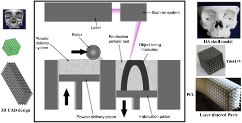
The SLS technique as depicted in figure uses a CO2 or Nd:YAG laser beam for scanning successive layers of powdered materials to create a 3D object [Citation10]. Based on slicing of the digital design, the scanning patterns of each layer are computed automatically [Citation11]. As is illustrated in figure , fabrication of the final parts using the SLS method includes two steps: 3D CAD design of the concept and transfer of the CAD data to the SLS machine to carry out fabrication with the desired powders.
Figure 1. Schematic of SLS from 3D CAD design to the laser sintering process. Reprinted from D N Silva 2008 J. Cranio-Maxillofacial Surg. 36 443–9, Copyright 2008, with permission from Elsevier; S Eshraghi and S Das 2010 Acta Biomater. 6 2467–76, Copyright 2010, with permission from Elsevier; and E Sallica-Leva et al 2013 J. Mech. Behav. Biomed. Mater. 26 98–108, Copyright 2013, with permission from Elsevier.
Each AM system has a unique binding mechanism to bind the layers. The binding mechanism of SLS technology can be classified into three main categories [Citation13, Citation15].
| • | Solid-state sintering, which is a thermal process. The binding mechanism in this category occurs between Tm/2 and Tm, wherein lies the melting temperature of the material in question. | ||||
| • | Liquid phase assisted sintering, which is commonly used for materials that are difficult to sinter. Liquid phase assisted sintering is the process of adding an additive to the powder which will melt before the matrix phase. This method is widely employed for fabrication of 3D parts from ceramic materials with incorporation of a small amount of polymers which will gradually decompose and completely disappear [Citation16]. | ||||
| • | Full melting, which is used for metallic and ceramic materials more than polymers. In this mechanism, near full density is reached in one step by melting the powders completely by laser beam, thus avoiding lengthy post-processing steps. | ||||
In the SLS method, material properties and process factors such as laser energy density, part bed temperature, layer thickness, and hatch distance affect the structural and mechanical properties of fabricated parts [Citation17, Citation18].
In this AM technique particle sizes in the range of 10–150 μm are preferred [Citation19]. The ideal laser energy density follows from the melting point of the binders (in the liquid phase sintering method) or powders (in the full melting technique) and can be set by adjusting the laser power and scan speed [Citation20].
By decreasing the laser scanning speed, denser parts may be obtained. This is caused by the longer interaction time between the powder and the laser beam, which boosts the rate of energy delivered to the powder bed [Citation21]. A higher laser scan speed results in less energy transferred to the materials [Citation22], leading to less sintering and in turn to more porosity. It should be noted that this case occurs especially in low melting point systems. Increasing the energy delivered to the powder bed promotes better melting of the powders, enabling more liquid phase to flow and infiltrate into the voids between the particles, which can lead to a denser structure [Citation21].
On the other hand, sufficiently high energy density leads to the complete melting of the binder, which reduces material delamination and increases the density of the fabricated parts. Although the higher energy density increases the mechanical properties of the final parts, it sometimes leads to inaccurate dimensions [Citation17]. As a practical matter, because the time of exposure of the material to the laser beam is too short, fabricating high-density parts is difficult. It is reported that an isothermal process as a second step using a furnace with a lower temperature than that obtained under the laser beam improves the density of the final parts [Citation23].
Tan et al [Citation24] have also conducted some preliminary laser sintering tests to determine the range of suitable processing parameters used in the SLS system. In their study, only one layer of material with 0.1 mm thickness was sintered to determine the parameter setting. First, they set the bed temperature to 110 °C and reported the formation of necks between particles at a laser energy of 12 W; however, there was delamination between the specimen layers. To improve the quality of the specimens, a higher bed temperature was used. In this study the optimum SLS processing factors were found to be 140 °C for the bed temperature and 12 W for the laser energy. For the materials with lower density and lower melting point, the applied laser power was lower [Citation19, Citation25, Citation26].
The effect of layer thickness on the open porosity of parts fabricated by SLS has been studied by Salvani et al [Citation20]. The results demonstrated that layer thickness has the greatest impact on the average pore width and on the proportion of pores with a proper size to facilitate bone regeneration. This phenomenon can be caused by thicker powder layers allowing less fusion between particles, resulting in less densification and higher open porosity. Table summarizes the effect of layer thickness on the average pore size of fabricated SLS samples.
Table 1. Effect of layer thickness on average pore width and proportion of pores of a suitable size in SLS [Citation20].
Similar results for the influence of layer thickness on the porosity and layer bonding have been obtained in other studies [Citation21]. It was concluded that smaller layer thickness leads to stronger bonding between the layers and decreases the porosity of the parts. Finding an optimum layer thickness is necessary depending on which application is desired. The minimum layer thickness that can be used effectively is determined by the maximum particle size of the powder. If a too-small layer thickness is chosen, the blade will drag non-melted large particles or chunks of melted particles, displacing the previous sintered layers from their position. Consequently, layer thickness for denser product must be set to the minimum layer thickness and vice versa [Citation21].
Hatch distance is another important parameter with respect to the properties of the parts fabricated by SLS. It has been confirmed that with a large increase in hatch distance in the prototype, there are dramatic changes in pore channels in its structure [Citation27]. The different microstructure resulting from a large hatch distance can be explained by the overlapping theory. Overlapping addresses to what degree a new laser line scans over the previously scanned track. Decreasing the hatch distance brings the scan lines closer to one another until they overlap. As an example, if the laser beam spot size is 0.4 mm, the parts processed with a hatch distance less than the laser spot size (e.g., 0.1, 0.2, and 0.3 mm) have different degrees of overlap. A large part of the laser spot may scan over a previously scanned line and accordingly increase the flowing and spreading of the liquid between adjacent scan lines, which leads to an enhancement of the inter-line bonding and a reduction in porosity. When a hatch distance of 0.4 mm is chosen, no overlapping is observed, resulting in appropriate connectivity of the matrix and a more porous part [Citation28].
Another phenomenon which can affect the surface morphology of samples fabricated by SLS is balling [Citation29, Citation30]. Balling is defined as an agglomeration of the particles, occurring where the liquid phase breaks up into a row of spheres to reduce surface energy. The main factor leading to balling is the Gibbs–Marangoni effect, which is the mass transfer along an interface between two fluids due to the surface tension gradient [Citation31]. In terms of temperature association, this phenomenon is also called thermo-capillary convection. Balling has a direct effect on creating large pores but is not a definitive solution for fabricating tissues with desired pores. Early experiments in using the SLS method for the fabrication of metallic parts confirmed balling during the process [Citation32]. To diminish the balling effect and consequently to have a uniformly sintered specimen, not only do the SLS parameters need to be set, but multiphase powders need to be designed by mixing different materials with various melting temperatures or by employing a pre-alloyed powder system in which melting takes place over a temperature range [Citation33, Citation34].
2.1. Commonly used materials in SLS
2.1.1. Polymers
Two types of thermoplastics are used in SLS: semi-crystalline and amorphous [Citation35]. An amorphous material has chain molecules arranged in a random manner, and semi-crystalline material has chain molecules arranged in an orderly structure. Semi-crystalline and amorphous materials have different thermal properties which determine the fabrication parameters in SLS.
The most important characteristics that determine the application of thermoplastic polymers are the glass transition temperature, Tg, and the melting temperature, Tm. The glass transition temperature Tg is the temperature where a rapid decrease in E (elastic modulus) occurs. It can be observed in amorphous material. Melting does not occur until the polymer reaches a higher temperature, Tm. Below Tg, the polymer is in the glass state and the molecular motion along the chain is frozen. When the temperature rises from Tg to approximately (Tg + 30 K), the molecular motion increases, causing the modulus to drop. Just above Tg, the polymer behaves like a highly viscous liquid in which the chains are all tangled up with their neighbors [Citation36, Citation37].
It has been also reported that a majority of semi-crystalline polymers have a glass transition temperature (Tg) below or close to room temperature (−100 to 50 °C) and a melting temperature (Tm) above 100 °C (between 100 and 400 °C) at which a considerable volume change occurs. On the other hand, amorphous polymers do not have a characteristic melting temperature range [Citation38]. They have a Tg of ∼100 °C, above which the material will progressively evolve to a leathery, rubbery, and finally liquid state as the temperature increases, with no obvious transitions [Citation38–Citation40]. It is important to mention that both Tg and Tm depend directly on molecular weight. This is why a different setup is needed to run an SLS system for different thermoplastic materials.
As mentioned, the power of the laser applied in an SLS system has an important effect on the mechanical properties of the fabricated models. For a semi-crystalline polymer powder, laser consolidation occurs by heating it to above its Tm since semi-crystalline powders have a molecular structure with spiky melt points. They do not gradually become softer with a temperature increase and remain hard until a given quantity of heat is absorbed and then quickly change into a viscous liquid. Shrinkage often happens simultaneously with freezing. To minimize this drawback, it is better to preheat the powders and to keep them in a furnace below their melting temperature for several hours [Citation38].
Consolidation of amorphous polymer powder happens by laser heating over Tg, at which point the polymer is in a much more viscous position than semi-crystalline polymers at a similar temperature [Citation41]. Unlike semi-crystalline polymers, amorphous polymers do not have a spiky melt point and soften slowly as the temperature rises. The viscosity of these materials changes when heated, but they seldom are as easy flowing as semi-crystalline materials.
There are a number of studies on using natural and synthesized polymers in SLS. For example, cellulose, the most abundant natural polymer [Citation42], has been used to fabricate SLS scaffolds [Citation18]. An important synthetic biodegradable polymer material is polycaprolactone (PCL) This material is semi-crystalline with high thermal stability and a degradation period of approximately two years [Citation43]. Due to the good biocompatibility, bioresorbability, and processability of PCL, this polymer is used for tissue engineering [Citation25] and cartilage repair [Citation44–Citation46].
2.1.2. Ceramics
SLS of ceramic materials can be either direct or indirect. Direct SLS of ceramics can be powder based or slurry based. In the powder-based method, the packing density of the powder layers is low, leading to a lower sintered density and also leading to cracks due to thermal stresses in the parts [Citation47]. Efforts have been made to develop direct SLS to produce fully dense ceramic composites [Citation48]. In this method high laser energy is applied to a preheated powder bed, causing the powder to melt and avoiding thermal stress cracking.
On the other hand, slurry-based direct SLS takes advantage of more homogeneous and much more densely packed powder layers obtained from the slurry process. The concern is that this method produces parts with lower strength due to thermal cracks and microstructural inhomogeneities [Citation49, Citation50].
Agglomeration of powders is a concern with using slurry-based SLS. An effective way to avoid agglomeration during laser sintering may be to process at a lower scanning speed or to employ a surfactant in a very low concentration [Citation51]. Using a surfactant helps obtain a homogeneous green part which can demonstrate better mechanical properties. This method is appropriate when the purpose is the fabrication of ceramic scaffolds with bioactive ceramics such as calcium silicate and hydroxyapatite. Calcium silicate (CS, CaSiO3) is a bioactive ceramic that has been explored for tissue engineering applications over the last two decades [Citation52–Citation55]. Many studies have shown that CS is able to form an apatite layer on its surface by soaking in simulated body fluid (SBF) [Citation55]. CS scaffolds with an interconnected pore structure can be made by SLS [Citation56]. Another commonly used ceramic in tissue engineering and the SLS method is hydroxyapatite (HA, Ca10(PO4)6(OH)2). HA is a calcium phosphate ceramic (CP) material that is biocompatible and bioactive due to its similarity to the mineral constituents of human bone and teeth [Citation57, Citation58]. Nanosized HA powder has a high specific surface area which can improve the sinterability and densification of scaffolds. Although pure CS and HA are known as biocompatible materials, the poor mechanical properties of fabricated scaffolds have limited their application [Citation53, Citation58].
The indirect method uses polymers as a binder with ceramic powders as the main matrix and involves the melting of sacrificial organic polymer to obtain a green part. The green parts are subsequently sintered to produce the final porous ceramic parts [Citation59]. Even though the materials used in this method include both polymer and ceramic as starting materials, the final part is pure ceramic and not a composite.
It has been confirmed that semi-crystalline polymers are preferred over amorphous polymers for use as the binder phase due to their higher density compared with amorphous polymers [Citation59]. However, semi-crystalline shrinks by 4–5 vol% upon solidification, causing component distortion. To reduce distortion, all material is preheated to just below Tm with SLS heating it in just a small window, i.e., the temperature window between the onset of polymer melting during heating and crystallization during cooling [Citation59, Citation60]. After SLS the part must be cooled to room temperature slowly.
Fabrication of scaffolds from bioactive glass materials using the indirect method has been reported. Bioactive glass materials with different compositions, e.g., 45S5, 58 S, and 13–93, can be used as scaffold materials [Citation17, Citation61, Citation62]. Bioactive glass materials have numerous advantages over other bioactive ceramics like sintered hydroxyapatite. For example, it has been shown that dissolution products from bioactive glasses upregulate the expression of genes that control osteogenesis [Citation63], which explains the high rate of bone formation [Citation64, Citation65].
2.1.3. Metals
Because metals possess excellent compressive strengths and also high fatigue resistance, porous metallic scaffolds such as titanium (Ti) and tantalum (Ta) and biocompatible alloys such as CoCr and nitinol have been proposed as bone replacement materials, but unlike bioactive ceramics or biocompatible polymeric scaffolds, biomolecules cannot be integrated into metallic scaffolds. The lack of degradability of metallic implants restricts the use of these kinds of scaffolds. The main concern with embedding metallic scaffolds is metal ion release into body fluid, leading to sarcoma. Coating the surface of metallic scaffolds with bioactive ceramics such as HA or CS or using surface finishing methods is highly recommended to improve the biological properties of metallic scaffolds [Citation66].
One category of SLS is selective laser melting (SLM), in which very high laser energy is applied to fully melt metals into a solid homogeneous mass. Different CoCrMo alloys meeting the requirements for tissue applications have been investigated to observe the effect of the laser melting process on corrosion and metal release in biologically relevant fluids [Citation67]. The strong temperature gradient as well as the rapid cooling during the laser melting process induces the formation of a fine cellular microstructure with molybdenum (Mo) enriched at the grain boundaries and suppresses the formation of large micron-sized carbides, resulting in higher corrosion resistance compared with cast alloy.
Dental implants have been fabricated from stainless steel and Ti6Al4V and CrCo alloys by the SLM method [Citation11]. For the consolidation of the powders, two different binding mechanisms are used, depending on the materials and alloys. The first mechanism is liquid phase sintering, where a polymer is liquefied by a laser beam with an energy density of 1 J mm−3 and acts as a binder for the stainless steel particles. This technique needs an additional heating cycle in which the polymer is burned out and the green part is further sintered and infiltrated with, e.g., bronze to reach a high density. The second technique is used for Ti6Al4V or CoCr alloy and consists of melting the metal powder completely by a laser beam with an energy density of 200 J mm−3, avoiding the need for post-processing. Further surface modification of the laser-melted Ti6Al4V alloy has shown improvement in biocompatibility and a reduction in post-implant complications [Citation68]. The alloys fabricated by SLM are functionalized with a pharmaceutically relevant biomolecule (paracetamol) using phosphonic acid–based self-assembled monolayers (SAMs) to be used as a biocompatible coating layer for drug and protein delivery [Citation68].
2.1.4. Composites
Polymers are elastic and have low stiffness, whereas ceramics are rigid and brittle [Citation69]. By mixing ceramics and polymers into composites, the mechanical properties are significantly improved because the problem of brittleness and the difficulty of shaping hard ceramics can be overcome [Citation53, Citation58, Citation70].
Numerous studies have been done to evaluate the potential of SLS in producing composite scaffolds containing polymer and ceramic [Citation19, Citation71, Citation72]. The main issue for ceramic/polymer composites is the agglomeration of ceramic powders into the polymer matrix. Using SLS for sintering, a mixture of ceramic and polymer powders can solve this problem due to the uniform distribution of ceramic into the matrix. Studies regarding SLS have included sintering hydroxyapatite powders coated with polymeric binders [Citation72, Citation73].
A study of scaffolds consisting of microspherical calcium phosphate (CP)/poly(hydroxybutyrate–co-hydroxyvalerate)(PHBV) and carbonated hydroxyapatite (CHA)/poly(L-lactic acid) (PLLA) has shown an improvement in biological properties. Laser-sintered HA/polyetheretherketone (PEEK) can also satisfy the requirements of tissues and scaffolds [Citation74]. PEEK, a synthetic polymer, is a semi-crystalline thermoplastic with excellent mechanical and chemical resistance properties, even at high temperatures. Its Young’s modulus is 3.6 GPa, and its tensile strength is 90 to 100 MPa [Citation75, Citation76]. PEEK has a glass transition at approximately 143 °C and melts at approximately 343 °C. Since PEEK has a much lower melting point than HA, it is possible to induce sintering of PEEK at temperatures near Tg and to bind and partially expose the HA particles within the sintered PEEK matrix.
Up to now, there have been few works regarding the fabrication of porous CS scaffolds using SLS and enhancing their mechanical properties by adding HA whiskers at the same time. In a previous study, porous scaffolds from CP materials with different weight ratios of TCP/HAP (0/100, 10/90, 30/70, 50/50, 70/30, and 100/0) were fabricated via SLS [Citation77].
2.2. Mechanical properties of SLS parts
Depending on the material and physical properties of the final products, various mechanical properties can be obtained for fabricated scaffolds. A high compressive strength of 18.2 ± 1.2 MPa has been reported for laser sintered CS scaffolds with an interconnected pore structure [Citation56]. Shuai et al [Citation78] have reported a Vickers hardness of 4.00 ± 0.13 GPa and a fracture toughness of 1.28 ± 0.03 MPa m1/2 for a scaffold made from high surface area HA nano powder by using SLS with a laser energy density of 4 J mm−2. Shuai et al [Citation79] have fabricated scaffolds via SLS of a composite of CS and poly(vinyl alcohol) (PVA). It was reported that the scaffolds could not be fabricated successfully due to decreased fusion between PVA particles when CS was higher than 20 wt%. For scaffolds containing 15 wt% CS, the compressive strength and compressive modulus reached optimum values of 184 ± 15 kPa and 1.6 ± 0.3 MPa, respectively. Tailoring the porous structure and interconnected pore network in the scaffolds has been reported to increase strength. Feng et al [Citation80] have been able to successfully fabricate a highly porous structure with a pore size of 0.5–0.8 mm and fully interconnected pore network scaffolds from HA whiskers incorporated into a CS matrix by SLS. They showed that applying SLS could enhance the compressive strength, compressive Young’s modulus, and fracture toughness of CS with HA whiskers ranging from 0 to 20 wt%. Moreover, for scaffolds made with cellulose material, the specimens with lower particle size showed a higher degree of sintering, a significant level of closed pores, and greater mechanical strength [Citation18].
An interesting work done by Gao et al [Citation62] has presented the mechanical properties of SLS scaffolds made with nano-58 S bioactive glass/graphene composite. Recently graphene, a 2D single layer of sp2 carbon atoms, has attracted great interest for producing the next generation of nanocomposites used in scaffold fabrication [Citation81]. Due to its superior biocompatibility and mechanical properties, graphene can be used in small amounts as a reinforcing phase in composites. The optimum compressive strength and fracture toughness of the 58 S/graphene scaffolds reached 49 ± 3 MPa and 1.9 ± 0.1 MPa m1/2 with a graphene content of 0.5 wt%, indicating significant improvement of 105% and 38% respectively compared with pure 58 S.
Velez et al [Citation82] have reported using of 13–93 bioactive glass with a chemical composition of 53% SiO2, 4% P2O5, 20% CaO, 5% MgO, 6% Na2O, and 12% K2O (wt%) for SLS scaffold fabrication. The compressive strength of the fabricated scaffolds was studied for up to two months when immersed in Dulbecco’s modified eagles medium (DMEM). The compressive strength of the parts decreased from 40 ± 10 MPa in the dry condition and 26 ± 6 MPa after 60 days. Porous biocompatible pure Ti and nitinol (NiTi) alloy was also successfully sintered into 3D scaffold form using a Nd:YAG laser with energy input of 100–300 J cm−2 [Citation83]. Nd:YAG lasers outperform CO2 lasers with respect to metallic powders due to better absorbance at shorter wavelengths [Citation84]. Applying the same laser energy during SLS resulted in a much smaller sintered depth of monolayers of NiTi powders compared with pure Ti, which causes lower mechanical strength. On the other hand, it is clear that the SLS parameters significantly affect fabricated tissues. As in previous studies, higher scanning velocity as well as laser power resulted in higher mechanical strength, as shown in table . Increasing the value of the scanning velocity prevents delaminating between the layers, resulting in enhancement of mechanical strength. This parameter is significant especially for the fabrication of metallic and alloy tissues by the SLM method.
Table 2. Mechanical properties and setup parameters of laser-melted Ti6Al4V alloy.
2.3. Biological properties of SLS parts: in vitro and in vivo studies
In vitro and in vivo tests play an important role in the biological assessment of biomaterials for the fabrication of tissues and scaffolds [Citation87]. A number of architectural characteristics, including porosity, pore size, and permeability, are significant parameters in biological delivery and tissue regeneration. In addition, the materials which are used for tissue engineering must possess a bioactive surface. The ability to control scaffold architecture can provide significant insights into how scaffold architecture and material affect tissue regeneration.
One issue regarding scaffolds made from polymers is the hydrophobic nature of their surface, which results in the negligible availability of bioactive sites [Citation58]. The presence of bioactive binding sites is necessary to induce cell–scaffold adhesion. Chen et al [Citation88] have reported a surface modification of PCL scaffolds made by SLS via immersion coating with collagen and gelatin. The collagen-modified scaffold was the best for cartilage tissue engineering in terms of cell proliferation and extracellular matrix production [Citation89]. PCL scaffolds fabricated by SLS can serve as osteoblast or osteogenic scaffolds. They are appropriate scaffolds for the proliferation of adipose-derived stem cells (ASCs) [Citation90]. The addition of bioactive ceramics to hydrophobic but biocompatible polymers is considered beneficial since it reduces the hydrophobicity of the polymer; therefore, it is more favorable for cell attachment and accelerates degradation. The effect of HA addition to a matrix of PCL on MC3T3 osteoblast activity has been examined [Citation71]. The proliferation of adhered cells and the formation of a cell layer on selective laser sintered composites of PCL/HA were observed, and osteoblasts were also encapsulated within the micropores of the struts. The cross sectional images from μCT confirm a remodeling of up to ∼400 μm into the microstructure of the struts. Alamar blue and alkaline phosphate activity (ALP) assays revealed that in general, in the initial period composites with lower HA content (15 wt%) showed better metabolic activity compared with those having higher HA content; however, by day 14 the performance of the two compositions was equal [Citation71].
Das et al have fabricated scaffolds from Nylon-6 by SLS [Citation91]. Biocompatibility tests showed that Nylon-6 scaffolds fabricated by SLS support cell viability very well. To investigate the biocompatibility of scaffolds, cells were either in direct contact with the Nylon-6 disks (CoCulture group) or subjected to conditioned media while in contact with the tissue culture polystyrene surface (Conditioned Media group). Two time points were investigated during this study: 3.5 days and 6.5 days in each group. Post-fabrication methods for fabricated scaffolds, e.g., cleaning and treatment, are significant in improving biocompatibility.
In vitro tests of 3D scaffolds have demonstrated that the incorporation of CP nanoparticles significantly improves cell proliferation [Citation19] and alkaline phosphatase activity for CP/PHBV scaffolds, whereas CHA/PLLA nanocomposite scaffolds exhibit a level of cell response comparable to PLLA polymer scaffolds. In vitro results have also revealed that the addition of bioactive CS ceramic into a PVA matrix (<20 wt%) enhances the bioactivity of scaffolds, i.e., the number of MG-63 cells attached to the surface of the composites increases in the presence of higher amounts of CS in the scaffolds [Citation79].
Williams et al [Citation25] have shown that when taking into account external shape and internal architecture, laser sintered scaffolds can support bone regeneration in vivo via gene therapy. Histological evaluation and μCT data show that the interior pore architecture of laser sintered PCL scaffolds can induce bone generation in vivo. Lohfeld et al [Citation92] have proposed the use of a biocomposite blend comprising PCL and TCP prepared by SLS. In vivo, a PCL/TCP composite scaffold showed inferior behavior compared with the reference material (β-TCP) with respect to a critical size defect regarding the promotion of bone regeneration, scaffold degradation, and inflammatory reaction. Saito et al [Citation93] have examined the effect of biomineral coating on bone regeneration for laser sintered PLLA and PCL scaffolds with the same porous architecture. As a result of bone ingrowth analysis after subcutaneous implantation into mice, coated scaffolds encouraged more penetration of bone interior to the scaffolds than uncoated scaffolds. Cross-sections of the biomineral-coated scaffolds showed good bone contact with the biomineral coatings as well as more bonelike tissue formation, indicating that the biomineral coatings supported direct bone formation rather than fibrous tissue formation.
More studies regarding the biological properties of laser sintered tissues and scaffolds from different materials are summarized in table .
Table 3. Summary of mechanical and biological properties of laser sintered tissues and scaffolds.
3. Inkjet 3DP technology
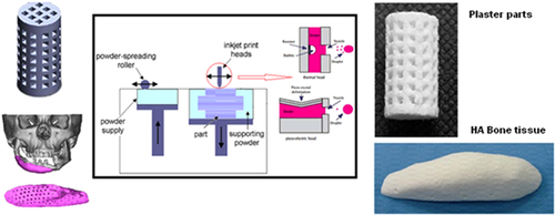
The binder jetting process is another AM technique which employs inkjet head (IJH) technology for processing materials. In this system, the head prints a liquid binder onto thin layers of powders based on object profiles that have been generated by software [Citation96]. Two kinds of drop-on-demand (DOD) heads can be used in IJH systems: piezoelectric and thermal heads. The main difference between these two heads is their performances. In thermal systems there is a heating element as a thin-film resistor. When an electrical pulse is applied at the head, a high current passes through this resistor and the fluid in contact with it is vaporized, forming a vapor bubble over the resistor. This vapor bubble expands in the fluid reservoir, and the increased pressure causes a droplet to be ejected through the nozzle [Citation97]. In the piezoelectric head system, a volumetric change in the fluid reservoir is induced by the application of a voltage pulse to a piezoelectric material element that is coupled, directly or indirectly, to the fluid. This volumetric change causes pressure/velocity transients to occur within the fluid, and these are directed to produce a drop that issues from the nozzle [Citation98]. Figure shows a layout of the inkjet printing process using both thermal and piezoelectric heads.
Figure 2. Layout of the inkjet 3DP process. Reproduced with from H Saijo et al 2009 J. Artif. Organs 12 200–5, with kind permission from Springer Science and Business Media and A Farzadi et al 2014 PloS One 9 e108252 under a CC BY 4.0 license.
Whether to use thermal or piezoelectric inkjet printers depends on the desired properties of the final part. Each inkjet technique has some points which can be categorized as availability, printing speed, accuracy of printed parts, and functional cost. Thermal inkjet printers have some advantages, including availability, higher print speed, and lower cost of parts fabrication compared with piezoelectric inkjet printers [Citation101]. However, the risk of exposing the binder to thermal stress, low droplet directionality, and nonuniform droplet size poses considerable disadvantages with respect to the use of these printers.
On the other hand the advantages of piezoelectric inkjet printers include the capability to generate and control uniform droplet size and ejection directionality as well as to avoid exposure of the binder to heat stressors [Citation102]. The shear stress imposed on the binder at the nozzle tip wall can be avoided by using an open-pool nozzleless ejection system which can also avoid the drawback of nozzle clogging. Adapting piezoelectric printers for less viscous binders in terms of lowering the frequency and power would be challenging since leakage and mist formation during printing may blur the pattern [Citation103, Citation104].
As the precision of fabricated models strongly depends on the velocity, initial size, and path of the droplets, it is essential to control the parameters, including nozzle diameter, binder properties, and resonance frequency of the head, which have a direct and indirect effect on these terms [Citation102].
3.1. Commonly used materials in inkjet 3DP
In general, a wide range of powders including ceramics and polymers can be processed by inkjet 3DP; however, binder selection is a key factor in successful part fabrication. This section provides a detailed discussion of the existing powders and binders which are used for the fabrication of tissues and scaffolds.
3.1.1. Binders
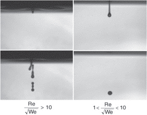
The materials used as a binder must have suitable properties to prevent spreading from nozzles. To adjust the fluid properties of the organic suspensions to be compatible with the type of printing head, the viscosity and surface tension must be 5–20 Pa.s and 35–40 mJ N−1, respectively. To obtain the aforesaid range, the ratio of should be between 1 and 10, where Re is the Reynolds number
and We is the Weber number
The values
and
are the ink density, viscosity, and surface tension respectively. V and r are droplet velocity and radius respectively [Citation105–Citation107]. When this ratio is too small, viscous forces predominate, which implies high pressure for ejection; inversely, if this ratio is too large, a continuous column is ejected that can lead to the formation of satellite drops behind the main drop. Figure shows the different cases observed according to the value of
The binder concentration also plays an important role in inkjet 3DP in achieving the desired dimensional precision [Citation108]. Three different types of binders are commonly used in the inkjet 3DP method: water-based binders such as certain commercial ones (e.g., ZB54, Z Corporation) [Citation100], phosphoric acid–based and citric acid–based binders [Citation109], and polymer solution binders such as PVA and poly(D,L-lactic acid) (PDLLA) [Citation110]. Depending on the type of binder, particles are bonded as the result of adhesive forces or a hydraulic setting reaction; i.e., phosphoric acid can react with tricalcium phosphate powder to produce a matrix of dicalcium phosphate dehydrate.
Figure 3. Ejection images of suspensions showing the effect of the ratio of . Reprinted from R Noguera et al 2005 J. Eur. Ceram. Soc.
25 2055–9, Copyright 2005, with permission from Elsevier.
Although polymeric binders have been widely used to fabricate ceramic parts, the final products suffer low resolution and mechanical strength. Using an acid binder solution has been suggested to improve the resolution and mechanical properties of the printed parts [Citation111]. Lyophilized bovine dermal type I collagen has been added to the phosphoric acid binder to improve the bone healing efficacy of the 3D printed scaffolds. The main concern in using collagen in the binder is the increase in viscosity. To cope with this problem a thermal head with a larger valve diameter must be used, which leads to decreased print resolution [Citation112].
3.1.2. Powders
Flowability of powders is an essential parameter for 3DP processing. Sufficient flowability of powders allows the roller to build up thin layers, leading to high 3DP resolution. Too little flowability decreases fabrication resolution due to insufficient recoating. On the other hand, very high flowability does not provide sufficient powder bed stability for 3DP.
Wettability of particles is another factor in 3DP processing. The volume of binder distributed into the powder bed and also the amount of binder absorbed by the powders determines the resolution (voxel size) and mechanical properties of the parts. It has been confirmed that too-low wetting of fine powder particles results in powder bed rearrangement that is possibly detrimental to further 3DP, and too-high wetting and slow powder reaction will reduce the smallest feature size [Citation113–Citation115]. The particle size of powders also has an effect on the mechanical strength of the printed parts. Changing the powder particle size alters the pore size distribution within the powder bed, which influences the drop penetration behavior of a water-based binder [Citation116].
For powder materials, a broad range of polymers, ceramics, and composites can be applied in the field of tissue engineering. As has been previously described the binding mechanism of bioceramic powders used in binder jetting systems is based on the hydraulic setting reaction [Citation117–Citation119]. When dry hydraulic cement is mixed with water, chemical reactions happen in the composite which cause the formation of a firm ceramic-based composite. Because of the nature of the compounds formed in these reactions, they are insoluble in water. This means that the hardened cement will retain its strength and hardness even if immersed in water.
CP has been widely applied in inkjet printing [Citation73, Citation120]. CP powders can be bound by aqueous (often acidic) binder solutions through a dissolution–precipitation reaction [Citation121]. Solution of a soluble polymeric binder [Citation122, Citation123] can be used for wet ceramic particles and can glue them together through drying. After the printing process, functioned parts are depowdered and the organic binder removed during sintering [Citation123–Citation125]. Table summarizes the most commonly used powder materials and binders for the production of tissues and scaffolds.
Table 4. Powders and binders used for tissue engineering.
3.2. Mechanical properties of inkjet 3DP parts
Improving the mechanical properties of porous parts is a challenge in inkjet 3DP. In some cases, to reach a suitable strength, the scaffolds are sintered after printing. This post-processing exposes the final part to failure due to the burnout of binder which is present or because of high binder concentration. Therefore, the binder concentration must be minimized while still providing sufficient mechanical stability to the printed structure. Moreover, sintering causes a dimensional change in the final part [Citation134]. Tarafder et al [Citation135] have reported a significant increase in the mechanical strength of macroporous TCP scaffolds via microwave sintering compared with conventional sintering. Saijo et al [Citation99] have fabricated parts with sufficient mechanical strength without using the sintering process. They propose that a reasonable mechanical strength for ceramic scaffolds can be achieved by optimizing the particle size of the powder and the pH and viscosity of the binder.
As mentioned in section 3.1.1, different experiments have been carried out to study the influence of binders on the properties of fabricated parts. In a study of the fabrication of 3D porous strontium-containing mesoporous bioactive glass scaffolds, the 3D printed scaffolds exhibited greater compressive strength (8–9 MPa) than the compressive strength of human trabecular bone (2–12 MPa) [Citation136]. In addition, the mechanical strength of a scaffold could be maintained at approximately 7 MPa after soaking in simulated body fluid (SBF). These results are attributed to the use of aqueous PVA binder, which bonds the ceramic particles together and consequently decreases the brittleness of the scaffolds. Wu et al [Citation110] have prepared a β-CS scaffold using 12% PVA solution as a binder. The compressive strength and Young’s modulus of printed CS scaffolds with a pore size of 1 × 1 mm and porosity of 65% were 3.6 ± 0.1 MPa and 40 ± 8 MPa. A study of the deformation of scaffolds during the compressive test revealed that the printed CS scaffolds partially maintained a scaffold configuration in the center position and only the border area collapsed. This may be interpreted as the effect of the proper distribution of polymeric binder on the flexibility of the printed scaffolds.
By comparing the compressive strength of CS scaffolds with those using polyurethane (PU) foam and PDLLA solutions to bind the particles, the influential role of binders in inkjet 3DP can be seen. The strengths of scaffolds prepared using PU and PDLLA solutions as binders were 0.3 and 1.45 MPa, respectively, i.e., significantly lower than when using a PVA solution [Citation137].
In the case of acidic binders, Vorndran et al [Citation111] have fabricated parts from β-TCP as the powder and phosphoric acid as the binder. They improved the compressive strength by adjusting the volume ratio of binder to powder. Compressive strengths of 3.4 and 7.4 MPa were obtained for a binder-to-powder-volume ratio of 2 and 4, respectively. Another study showed that an 8.75 wt% phosphoric acid solution binder can improve mechanical strength while retaining cell viability at 68% ± 6%. As a surfactant, 0.25 wt% Twin 80 was added to the binder solution to improve printability [Citation132].
As mentioned earlier, the size of the powder particles has a direct influence on the mechanical strength of the parts. In HA/CaSO4 (calcium sulfate) composites it was confirmed that using very fine HA powders (≤20 μm) leads to a loosely packed powder bed and thus a high level of heterogeneity, which results in slow drop penetration, large drop penetration depth, low wetting ratio, and poor green mass and green strength for the final 3DP components. On the other hand, using coarser HA powders (30–100 μm) can show higher mechanical strength values [Citation133]. Printing the parts along different axes also has an effect on mechanical strength. Composites of HA/PVA as bone tissue have shown different mechanical behaviors along different printing axes [Citation138]. The mechanical strength for X-axis scaffolds has been reported as 0.76 ± 0.02 MPa, whereas this value is 0.88 ± 0.02 MPa along the Y-axis. Despite exhibiting a higher compressive strength, scaffolds printed along the Y-axis have been shown to contain traces of PVA degradation products after heat treatment. Using metal oxide components as a reinforcement agent is also recommended to improve the mechanical properties of bioactive ceramics, especially for hard tissues and implant applications [Citation139, Citation140]. Moreover, the addition of SiO2/ZnO to TCP can increase the mechanical properties of implants. For investigation of this effect, Fielding et al [Citation120] fabricated a cylindrical scaffold by binder jetting with the addition of SiO2/ZnO. Cylindrical scaffold CAD files were created with interconnected square channels of 1000 μm, 750 μm, and 500 μm sides and 7 mm diameter and 10.5 mm height. The doped fabricated scaffolds, which had less total open pore volume than the pure scaffolds, showed the greatest compressive strength, with the 1000 μm, 750 μm, and 500 μm green channel sizes at 10.21 ± 0.11 MPa, 8.2 ± 0.4 MPa, and 4.34 ± 0.3 MPa, respectively. The pure samples with the green channel sizes 1000 μm, 750 μm, and 500 μm had average compressive strengths of 5.48 ± 0.04 MPa, 2.7 ± 0.2 MPa, and 1.8 ± 0.2 MPa, respectively.
3.3. Biological properties of inkjet 3DP parts: in vitro and in vivo studies
Apart from having good mechanical properties, tissues and scaffolds fabricated by inkjet 3DP must be able to react with cells after implantation. Improving the biological properties (biocompatibility, biodegradability, and cell proliferation) of printed tissues depends on the properties of powders and binders, on pore volume, and also on post-processing of printed tissues.
As previously discussed, in some cases poor mechanical strength of printed tissues can be improved by the sintering process. However, sintering may also compromise biodegradability due to increases in the crystallinity of printed parts, leading to poor resorption by osteoclasts [Citation99]. The binder properties also play a crucial role in the biological properties. The effect of binder solution acidity on the biological properties of printed calcium phosphate scaffolds has been demonstrated by Inzana et al [Citation132]. Although higher acidity of binders results in greater mechanical strength of scaffolds, it also increases toxicity. Phosphoric acid of 12.5 wt% almost leads to cell death due to the pH of media falling below 5 [Citation132].
A report by Becker et al [Citation141] has presented the prototyping of three scaffolds of HA, TCP, and TCP and bovine HA composites by binder jetting technology. Aqueous solutions of dextrin (20 wt%) and saccharose (2.5 wt%) were used as the binder. After in vivo tests and cell seeding, it was concluded that 3D-printed hydroxyapatite and 3D-printed TCP as well as bovine HA blocks are biocompatible for cells derived from a human periosteum.
Studies have shown that zinc oxide has a stimulatory influence on fabricated tissue formation in vitro and in vivo and also increases the ALP of TCP/zinc oxide composite, which is an enzymatic marker for osteoblastic differentiation [Citation142, Citation143].
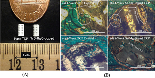
Since bone can grow into pores with a diameter of approximately 300 μm, providing pores of this size or larger is essential for bone grafting. Depending on whether post-processing is used, pores with the desirable geometry can be created by considering the pore size and geometry in the primary design of the structure or can be derived from porogens burned out during sintering. Pore geometry is known to be an important factor in determining bone healing response [Citation144]. The addition of dopants in bioactive ceramics such as TCP can also affect osteogenic differentiation via modification of pore size. Although in many cases cation substitutions such as Na+, Mg2+, and Sr2+ have led to excellent improvement in the biological properties of HA, only a few studies have investigated the effect of cation doping on the 3D interconnected porosity of 3D printed tissues and scaffolds. Both micro and interconnected macropores facilitate the infiltration of osteoprogenitor cells, which emphasizes the presence of multiscale porosity in tissue engineering scaffolds. In a research conducted by Tarafder et al [Citation145], the presence of Mg2+and Sr2+ in a TCP structure and their influence on 3D printed bone tissues led to pore sizes of 245 ± 8 μm and 311 ± 6 μm for doped and pure TCP scaffolds, respectively, which were close to the designed pore size of 350 μm [Citation145]. As shown in figure , improvement of bone formation inside macropores (when tested in rat femoral defects) was observed in microwave sintered Mg/Sr-doped TCP tissues. Interconnected pores made by inkjet 3DP result in good cell–tissue reaction, which leads to the development of new bone formation and bone remodeling inside the interconnected macropores and intrinsic micropores of 3D printed scaffolds.
Figure 4. (A) 3D printed tissues; (B) microscopy image of (a) and (c) 3DP pure TCP implants and (b) and (d) Sr/Mg-doped TCP implants, showing the development of new bone formation and bone remodeling inside the interconnected macro and intrinsic micro pores of 3DP scaffolds after four and eight weeks in a rat distal femur model. Modified Masson–Goldner trichrome staining of transverse section. OB: old bone, NB: new bone, O: osteoid, and BM: bone marrow. Color description: dark gray/black = scaffold; orange/red = osteoid; green/bluish = new mineralized bone (NMB)/old bone. Reproduced from S Tarafder et al 2013 Biomater. Sci. 1 1250–9, with permission of The Royal Society of Chemistry.
Another in vivo study has also revealed the effect of pores on bone formation after implantation, i.e., cylindrical holes 2 mm in diameter running across 3D printed tailor-made bone implants (TIs) showed that bone formation on a larger scale was facilitated [Citation131]. Based on computed tomography (CT) analysis of the skulls of beagle dogs, the volume of the cylindrical holes decreased after the operation, and histological analysis revealed that newly formed bone tissue had invaded the cylindrical holes. Not only can TIs fabricated by an inkjet 3D printer facilitate bone healing due to the excellent natural properties of TCP, but a properly designed hole in the implant structure can also improve bone healing [Citation131].
4. Key issues and challenges to clinical applications
AM offers unique advantages with respect to fabrication tissues and scaffolds with a complex external anatomy shape and internal porous structure. Coupling complicated porous 3D design with AM techniques can create a range of bone tissues and scaffolds from various materials. Among the AM techniques, inkjet 3DP and SLS are two powder-based tools which are widely used for biomedical engineering applications.
In the case of SLS, the initial setting, e.g., laser power and scanning speed, is crucial. Without any modification, commercial SLS machines can be used only for small amounts of powdered materials for fabricating specific biomedical applications. Different research groups have begun to optimize the SLS parameters for fabricating special objects with a desired 3D porous architecture in minimum fabrication time and at minimal cost. For tissue engineering, control over mechanical behavior while retaining the designed porous structure is very important. This issue can restrict the use of pure biocompatible polymers. Another disadvantage of the SLS technique for scaffold fabrication is that hydrogels cannot be processed, and it is also impossible to encapsulate cells in scaffolds [Citation84]. The lack of vascularization within scaffolds is still a major concern for scaffolds targeting specific tissue regeneration. Non-fine feature resolution of the SLS technique is a particular drawback which can affect fabricated tissues in terms of cell seeding and growth-factor delivery.
In the case of using inkjet 3DP machines for tissue engineering, although this method can be employed for fabricating tissues with defined shapes and porous architecture from almost all ceramics and polymer materials, the selecting of a suitable binder is still a challenge which needs extensive optimization. Among the binders, acidic ones can provide good mechanical properties for fabricated tissues; however, binder residue in printed structures is difficult to remove and may make tissues toxic. In most cases, post-processing such as sintering is required for printed parts to achieve the desired mechanical behavior. During the sintering process, parts shrink, and unfortunately the shrinkage is not necessarily uniform. The first effect of non-uniform shrinkage on sintered parts is cracking, which make the parts useless. Since the outside part of bone is denser than the inner part, mimicking such structures is very difficult using 3DP, which is the second challenge related to non-uniform shrinkage during sintering [Citation146]. Another post-processing challenge is the removal of loose powders from interconnected pores inside the part. This problem is highlighted for structures with small pores (<600 μm). Trapped powders inside the pores may well sinter with the porous part, making it less interconnected than the designed part. Such problems with loose powders can reduce the dimension of the pores after sintering.
Apart from the issues related to SLS and inkjet 3DP settings as well as selecting suitable biomaterials, clinical usage of AM processed parts is still a big challenge. In fact, there are many obstacles along this long and difficult road.
The gap between the concept and the clinical use of tissue engineering comprises three main factors: the need for understanding native-tissue characterization, the need to incorporate this characterization into tissue design, and finally, the necessity of fabricating tissues based on these design specifications. Despite all the advances in biomaterials science, there are still major gaps in this field relative to the surface chemistry, growth factor release, and mass-transport characteristics that best accelerate a specific tissue formation. Therefore, there are no strategies specifying which material is appropriate for tissues, which linear or nonlinear elastic properties a scaffold should exhibit, which surface chemistry a scaffold should have, or which permeability or diffusion properties a scaffold should demonstrate. In addition to these gaps and challenges, the clinical use of artificial tissues and scaffolds needs volunteer patients for bone tissue replacement surgeries. Because this field is still new and not much clinical surgery has been done, this high-risk surgery might pose challenges after implantation.
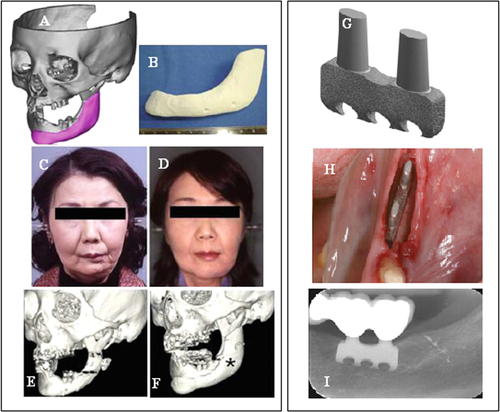
Few SLS and ink jet printing products have been used in clinical applications. Most reports have been limited to using models as guide templates for surgery and for in vitro and in vivo experiments, whereas implantations of scaffolds in the human body are still rare. The union between produced parts and host bones is affected by dimensional compatibility, biodegradability, pore size, and pore interconnectivity. Saijo et al [Citation99] have reported a maxillofacial reconstruction by using a custom-made artificial bone made by an inkjet printer. The bone was fabricated with a macropore structure and no sintering process, using α-TCP powder with 10 μm particle diameter and a mixture of 5% sodium chondroitin sulfate, 12% disodium succinate, and 83% distilled water as a curing solution. The scaffolds showed rapid union in 10 patients at 12 months after implantation, which can be attributed to the implant macropore structure resulting in rapid cell growth [Citation147]. Recently Mangano et al [Citation148] reported a clinical use of SLS titanium (master alloy powder (Ti6Al4V)) blade implants as a non-conventional solution for the prosthetic rehabilitation of extremely atrophied posterior mandibles. Two years after loading, all implants were in good condition and demonstrated perfect aesthetic integration. Compared with conventional approaches such as bone reconstructive surgery, the use of cost-effective SLS implants as a therapeutic treatment can represent an alternative for elderly patients because of lower morbidity. Figure illustrates such custom-made artificial bones fabricated through the use of inkjet 3DP and SLS for clinical applications.
Figure 5. Clinical application of custom-made artificial bone from α-TCP using inkjet 3D printing (left) (reproduced from H Saijo et al 2009 J. Artif. Organs 12 200–5, with kind permission from Springer Science and Business Media) and custom-made SLS titanium blade implants (right) (reproduced from F Mangano et al C 2013 Lasers Med. Sci. 28 1241–7, with kind permission from Springer Science and Business Media). Left: (A) Extraction of the CAD data of the created artificial bone (red) based on a CT image. (B) Macroscopic image of the inkjet-printed custom-made artificial bone (IPCAB). (C) Facial appearance 1 year after surgery. (D) 3D CT image of the left lower jaw before surgery. (E) 3D CT image of the left lower jaw 12 months after surgery. Right: (G) CAD file of the custom-made SLS titanium blade implant. (H) The custom-made SLS blade implant placed in position. (I) The radiographic control two years after implant placement.
Demand for AM technologies such as SLS and 3DP will increase in the future due to their capability to make custom medical devices that can be tailored for patient-specific and defect-specific clinical needs. Integrating all key points mentioned as well as finding solutions to cope with the challenges and issues are important in guiding the progress of these techniques toward achieving the objective of clinical use.
Acknowledgments
This study was funded by the Ministry of Higher Education of Malaysia (MOHE), Grant Number UM.C/HIR/MOHE/ENG/10 D000010-16001, entitled ‘Biomechanical System for Hard Tissues of Normal and Disable Subjects’, and research grant numbers IPP PG012-2012B and UMRG RP021-2012A, supported by the University of Malaya. The authors are also grateful for further support from the ‘Bright Spark’ Unit.
References
- HutmacherD WSittingerMRisbudM V 2004 Scaffold-based tissue engineering: rationale for computer-aided design and solid free-form fabrication systems Trends Biotechnol. 22 354 362 354–62 10.1016/j.tibtech.2004.05.005
- PhamD TGaultR S 1998 A comparison of rapid prototyping technologies Int. J. Mach. Tools Manuf. 38 1257 1287 1257–87 10.1016/S0890-6955(97)00137-5
- WendelBRietzelDKühnleinFFeulnerRHülderGSchmachtenbergE 2008 Additive processing of polymers Macromol. Mater. Eng. 293 799 809 799–809 10.1002/mame.200800121
- MelchelsF P WFeijenJGrijpmaD W 2010 A review on stereolithography and its applications in biomedical engineering Biomaterials 31 6121 6130 6121–30 10.1016/j.biomaterials.2010.04.050
- OnuhS OYusufY Y 1999 Rapid prototyping technology: applications and benefits for rapid product development J. Intell. Manuf. 10 301 311 301–11 10.1023/A:1008956126775
- GibsonIRosenD WStuckerB 2010 Additive Manufacturing Technology New York Springer
- WarnkeP HSeitzHWarnkeFBeckerS TSivananthanSSherryELiuQWiltfangJDouglasT 2010 Ceramic scaffolds produced by computer-assisted 3D printing and sintering: characterization and biocompatibility investigations J. Biomed. Mater. Res. B: Appl. Biomater. 93B 212 217 212–7 10.1002/jbm.b.31577
- RahmatiSAbbaszadehFFarahmandF 2012 An improved methodology for design of custom-made hip prostheses to be fabricated using additive manufacturing technologies Rapid Prototyping J. 18 389 400 389–400 10.1108/13552541211250382
- BohnerMvan LentheG HGrunenfelderSHirsigerWEvisonRMullerR 2005 Synthesis and characterization of porous beta-tricalcium phosphate blocks Biomaterials 26 6099 6105 6099–105 10.1016/j.biomaterials.2005.03.026
- KoS HPanHGrigoropoulosC PLuscombeC KFréchetJ M JPoulikakosD 2007 All-inkjet-printed flexible electronics fabrication on a polymer substrate by low-temperature high-resolution selective laser sintering of metal nanoparticles Nanotechnology 18 345202 10.1088/0957-4484/18/34/345202
- KruthJ PVandenbrouckeBVan VaerenberghJNaerI 2005 Rapid manufacturing of dental prostheses by means of selective laser sintering/melting Proc. AFPR, S4 Netherlands
- SilvaD NGerhardt de OliveiraMMeurerEMeurerM ILopes da SilvaJ VSanta-BárbaraA 2008 Dimensional error in selective laser sintering and 3D-printing of models for craniomaxillary anatomy reconstruction J. Cranio-Maxillofacial Surg. 36 443 449 443–9 10.1016/j.jcms.2008.04.003
- EshraghiSDasS 2010 Mechanical and microstructural properties of polycaprolactone scaffolds with one-dimensional, two-dimensional, and three-dimensional orthogonally oriented porous architectures produced by selective laser sintering Acta Biomater. 6 2467 2476 2467–76 10.1016/j.actbio.2010.02.002
- Sallica-LevaEJardiniA LFogagnoloJ B 2013 Microstructure and mechanical behavior of porous Ti–6Al–4 V parts obtained by selective laser melting J. Mech. Behav. Biomed. Mater. 26 98 108 98–108 10.1016/j.jmbbm.2013.05.011
- VaeziMSeitzHYangS 2013 A review on 3D micro-additive manufacturing technologies Int. J. Adv. Manuf. Technol. 67 1721 1754 1721–54 10.1007/s00170-012-4605-2
- ShuaiCZhuangJPengSWenX 2014 Inhibition of phase transformation from β-to α-tricalcium phosphate with addition of poly (L-lactic acid) in selective laser sintering Rapid Prototyping J. 20 369 376 369–76 10.1108/RPJ-03-2013-0037
- KolanK CLeuM CHilmasG EVelezM 2012 Effect of material, process parameters, and simulated body fluids on mechanical properties of 13–93 bioactive glass porous constructs made by selective laser sintering J. Mech. Behav. Biomed. Mater. 13 14 24 14–24 10.1016/j.jmbbm.2012.04.001
- SalmoriaG VKlaussPPaggiR AKanisL ALagoA 2009 Structure and mechanical properties of cellulose based scaffolds fabricated by selective laser sintering Polym. Test. 28 648 652 648–52 10.1016/j.polymertesting.2009.05.008
- DuanBWangMZhouW YCheungW LLiZ YLuW W 2010 Three-dimensional nanocomposite scaffolds fabricated via selective laser sintering for bone tissue engineering Acta Biomater. 6 4495 4505 4495–505 10.1016/j.actbio.2010.06.024
- SavalaniM MHaoLDickensP MZhangYTannerK EHarrisR A 2012 The effects and interactions of fabrication parameters on the properties of selective laser sintered hydroxyapatite polyamide composite biomaterials Rapid Prototyping J. 18 16 27 16–27 10.1108/13552541211193467
- AmorimF LLohrengelANeubertVHigaC FCzelusniakT 2014 Selective laser sintering of Mo-CuNi composite to be used as EDM electrode Rapid Prototyping J. 20 59 68 59–68 10.1108/RPJ-04-2012-0035
- GuDShenY 2008 Influence of Cu-liquid content on densification and microstructure of direct laser sintered submicron W–Cu/micron Cu powder mixture Mater. Sci. Eng.: A 489 169 177 169–77 10.1016/j.msea.2007.12.008
- FengPNiuMGaoCPengSShuaiC 2014 A novel two-step sintering for nano-hydroxyapatite scaffolds for bone tissue engineering Sci. Rep. 4 5599 10.1038/srep05599
- TanK HChuaC KLeongK FCheahC MCheangPAbu BakarM SChaS W 2003 Scaffold development using selective laser sintering of polyetheretherketone–hydroxyapatite biocomposite blends Biomaterials 24 3115 3123 3115–23 10.1016/S0142-9612(03)00131-5
- WilliamsJ MAdewunmiASchekR MFlanaganC LKrebsbachP HFeinbergS EHollisterS JDasS 2005 Bone tissue engineering using polycaprolactone scaffolds fabricated via selective laser sintering Biomaterials 26 4817 4827 4817–27 10.1016/j.biomaterials.2004.11.057
- GoodridgeR DTuckC JHagueR J M 2012 Laser sintering of polyamides and other polymers Prog. Mater. Sci. 57 229 267 229–67 10.1016/j.pmatsci.2011.04.001
- SachdevaASinghSSharmaV 2013 Investigating surface roughness of parts produced by SLS process Int. J. Adv. Manuf. Technol. 64 1505 1516 1505–16 10.1007/s00170-012-4118-z
- GuDShenY 2009 Effects of processing parameters on consolidation and microstructure of W–Cu components by DMLS J. Alloys Compd. 473 107 115 107–15 10.1016/j.jallcom.2008.05.065
- WalkerD CCaleyW FBrochuM 2014 Selective laser sintering of composite copper–tin powders J. Mater. Res. 29 1997 2005 1997–2005 10.1557/jmr.2014.194
- WangJYangMZhangY 2014 A nonequilibrium thermal model for direct metal laser sintering Numer. Heat. Tr. A—Appl. 67 249 267 249–67 10.1080/10407782.2014.923231
- AsgharzadehHSimchiA 2005 Effect of sintering atmosphere and carbon content on the densification and microstructure of laser-sintered M2 high-speed steel powder Mater. Sci. Eng.: A 403 290 298 290–8 10.1016/j.msea.2005.05.017
- GuD DShenY F 2006 Influence of phosphorus element on direct laser sintering of multicomponent Cu-based metal powder Metall. Mater. Trans. B 37 967 977 967–77 10.1007/BF02735019
- KruthJ-PKumarSVan VaerenberghJ 2005 Study of laser-sinterability of ferro-based powders Rapid Prototyping J. 11 287 292 287–92 10.1108/13552540510623594
- DasSBeamaJ JWohlertMBourellD L 1998 Direct laser freeform fabrication of high performance metal components Rapid Prototyping J. 4 112 117 112–7 10.1108/13552549810222939
- AjokuUHopkinsonNCaineM 2006 Experimental measurement and finite element modelling of the compressive properties of laser sintered Nylon-12 Mater. Sci. Eng.: A 428 211 216 211–6 10.1016/j.msea.2006.05.019
- BiceranoJSeitzJ T 1996 Molecular origins of toughness in polymers Polymer Toughening New York Dekker 1 59 pp 1–59
- WisanrakkitGGillhamJ 1990 The glass transition temperature (Tg) as an index of chemical conversion for a highTg amine/epoxy system: chemical and diffusioncontrolled reaction kinetics J. Appl. Polym. Sci. 41 2885 2929 2885–929 10.1002/app.1990.070411129
- KruthJ PLevyGKlockeFChildsT H C 2007 Consolidation phenomena in laser and powder-bed based layered manufacturing CIRP Ann—Manuf. Technol. 56 730 759 730–59 10.1016/j.cirp.2007.10.004
- SchmidtMPohleDRechtenwaldT 2007 Selective laser sintering of PEEK CIRP Ann—Manuf. Technol. 56 205 208 205–8 10.1016/j.cirp.2007.05.097
- HoH C HCheungW LGibsonL 2002 Effects of graphite powder on the laser sintering behaviour of polycarbonate Rapid Prototyping J. 8 233 242 233–42 10.1108/13552540210441148
- BeamanJ JBarlowJ WBourellD LCrawfordR HMarcusH LMcAleaK P 1997 Solid Freeform Fabrication: A New Direction in Manufacturing Dordrecht Kluwer Academic
- GharehkhaniSSadeghinezhadEKaziS NYarmandHBadarudinASafaeiM RZubirM N M 2015 Basic effects of pulp refining on fiber properties—a review Carbohydrate Polym. 115 785 803 785–803 10.1016/j.carbpol.2014.08.047
- GunatillakeP AAdhikariR 2003 Biodegradable synthetic polymers for tissue engineering Eur. Cells Mater. 5 1 16 1–16
- SabirM IXuXLiL 2009 A review on biodegradable polymeric materials for bone tissue engineering applications J. Mater. Sci. 44 5713 5724 5713–24 10.1007/s10853-009-3770-7
- MkhabelaV JRayS S 2014 Poly (∊-caprolactone) nanocomposite scaffolds for tissue engineering: a brief overview J. Nanosci. Nanotechnol. 14 535 545 535–45 10.1166/jnn.2014.9055
- YeongWSudarmadjiNYuHChuaCLeongKVenkatramanSBoeyYTanL 2010 Porous polycaprolactone scaffold for cardiac tissue engineering fabricated by selective laser sintering Acta Biomater. 6 2028 2034 2028–34 10.1016/j.actbio.2009.12.033
- BertrandPBayleFCombeCGoeuriotPSmurovI 2007 Ceramic components manufacturing by selective laser sintering Appl. Surf. Sci. 254 989 992 989–92 10.1016/j.apsusc.2007.08.085
- HagedornY CBalachandranNMeinersWWissenbachKPopraweR 2011 SLM of net-shaped high strength ceramics: new opportunities for producing dental restorations Proc. Solid Freeform Fabrication Symp. (Austin, TX) 8 10 pp 8–10
- TangH-HChiuM-LYenH-C 2011 Slurry-based selective laser sintering of polymer-coated ceramic powders to fabricate high strength alumina parts J. Eur. Ceram. Soc. 31 1383 1388 1383–8 10.1016/j.jeurceramsoc.2011.02.020
- ShahzadKDeckersJKruthJ-PVleugelsJ 2013 Additive manufacturing of alumina parts by indirect selective laser sintering and post processing J. Mater. Process. Technol. 213 1484 1494 1484–94 10.1016/j.jmatprotec.2013.03.014
- LiuF-H 2014 Synthesis of biomedical composite scaffolds by laser sintering: Mechanical properties and in vitro bioactivity evaluation Appl. Surf. Sci. 297 1 8 1–8 10.1016/j.apsusc.2013.12.130
- LiuXMorraMCarpiALiB 2008 Bioactive calcium silicate ceramics and coatings Biomed. Pharmacother. 62 526 529 526–9 10.1016/j.biopha.2008.07.051
- ShuaiCFengPYangBCaoYMinAPengS 2014 Effect of nanozirconia on the mechanical and biological properties of calcium silicate scaffolds Int. J. Appl. Ceram. Technol. at press ( 10.1111/ijac.12337 )
- HazarA B Y 2007 Preparation and in vitro bioactivity of CaSiO3 powders Ceram. Int. 33 687 692 687–92 10.1016/j.ceramint.2006.12.013
- ShiraziF SMoghaddamEMehraliMOshkourA AMetselaarH S CKadriN AZandiKAbuN A 2014 In vitro characterization and mechanical properties of β-calcium silicate/POC composite as a bone fixation device J. Biomed. Mater. Res. A 102 3973 3985 3973–85 10.1002/jbm.a.35074
- ShuaiCMaoZHanZPengSLiZ 2014 Fabrication and characterization of calcium silicate scaffolds for tissue engineering J. Mech. Med. Biol. 14 1450049 10.1142/S0219519414500493
- TanKChuaCLeongKCheahCCheangPBakarM AChaS 2003 Scaffold development using selective laser sintering of polyetheretherketone–hydroxyapatite biocomposite blends Biomaterials 24 3115 3123 3115–23 10.1016/S0142-9612(03)00131-5
- WiriaFLeongKChuaCLiuY 2007 Poly-∊-caprolactone/hydroxyapatite for tissue engineering scaffold fabrication via selective laser sintering Acta Biomater. 3 1 12 1–12 10.1016/j.actbio.2006.07.008
- ShahzadKDeckersJZhangZKruthJ-PVleugelsJ 2014 Additive manufacturing of zirconia parts by indirect selective laser sintering J. Eur. Ceram. Soc. 34 81 89 81–9 10.1016/j.jeurceramsoc.2013.07.023
- DrummerDRietzelDKühnleinF 2010 Development of a characterization approach for the sintering behavior of new thermoplastics for selective laser sintering Phys. Proc. 5 533 542 533–42 10.1016/j.phpro.2010.08.081
- BoseSRoyMBandyopadhyayA 2012 Recent advances in bone tissue engineering scaffolds Trends Biotechnol. 30 546 554 546–54 10.1016/j.tibtech.2012.07.005
- GaoCLiuTShuaiCPengS 2014 Enhancement mechanisms of graphene in nano-58 S bioactive glass scaffold: mechanical and biological performance Sci. Rep. 4 4712 10.1038/srep04712
- XynosI DHukkanenM V JBattenJ JButteryL DHenchL LPolakJ M 2000 Bioglass (R) 45S5 stimulates osteoblast turnover and enhances bone formation in vitro: implications and applications for bone tissue engineering Calcif. Tissue Int. 67 321 329 321–9 10.1007/s002230001134
- BoccacciniA RErolMStarkW JMohnDHongZ KManoJ F 2010 Polymer/bioactive glass nanocomposites for biomedical applications: a review Compos. Sci. Technol. 70 1764 1776 1764–76 10.1016/j.compscitech.2010.06.002
- WheelerD LMontfortM JMcLoughlinS W 2001 Differential healing response of bone adjacent to porous implants coated with hydroxyapatite and 45S5 bioactive glass J. Biomed. Mater. Res. 55 603 612 603–12 10.1002/1097-4636(20010615)55:4<603::AID-JBM1054>3.0.CO;2-N
- HuangYHanSPangXDingQYanY 2013 Electrodeposition of porous hydroxyapatite/calcium silicate composite coating on titanium for biomedical applications Appl. Surf. Sci. 271 299 302 299–302 10.1016/j.apsusc.2013.01.187
- HedbergY SQianBShenZVirtanenSOdnevall WallinderI 2014 In vitro biocompatibility of CoCrMo dental alloys fabricated by selective laser melting Dental Mater. 30 525 534 525–34 10.1016/j.dental.2014.02.008
- VaithilingamJKilsbySGoodridgeR DChristieS D REdmondsonSHagueR J M 2015 Functionalisation of Ti6Al4V components fabricated using selective laser melting with a bioactive compound Mater. Sci. Eng.: C 46 52 61 52–61 10.1016/j.msec.2014.10.015
- ShiraziF SMehraliMAtaollahi OshkourACornelis MetselaarH SKadriN AAbu OsmanN A 2013 Characterization and mechanical properties of calcium silicate/citric acid–based polymer composite materials Int. J. Appl. Ceram. Technol. 12 371 376 371–6 10.1111/ijac.12151
- ShorLGüçeriSWenXGandhiMSunW 2007 Fabrication of three-dimensional polycaprolactone/hydroxyapatite tissue scaffolds and osteoblast-scaffold interactions in vitro Biomaterials 28 5291 5297 5291–7 10.1016/j.biomaterials.2007.08.018
- EosolySVranaN ELohfeldSHindieMLooneyL 2012 Interaction of cell culture with composition effects on the mechanical properties of polycaprolactone-hydroxyapatite scaffolds fabricated via selective laser sintering (SLS) Mater. Sci. Eng.: C 32 2250 2257 2250–7 10.1016/j.msec.2012.06.011
- ChuaC KLeongK FTanK HWiriaF ECheahC M 2004 Development of tissue scaffolds using selective laser sintering of polyvinyl alcohol/hydroxyapatite biocomposite for craniofacial and joint defects J. Mater. Sci., Mater. Med. 15 1113 1121 1113–21 10.1023/B:JMSM.0000046393.81449.a5
- BoseSTarafderSBanerjeeSBandyopadhyayA 2011 Biomaterials Science—Processing, Properties, and Applications New York Wiley 135 145 pp 135–45
- MaRTangT 2014 Current strategies to improve the bioactivity of PEEK Int. J. Mol. Sci. 15 5426 5445 5426–45 10.3390/ijms15045426
- PuppiDChielliniFPirasA MChielliniE 2010 Polymeric materials for bone and cartilage repair Prog. Polym. Sci. 35 403 440 403–40 10.1016/j.progpolymsci.2010.01.006
- HanC-MLeeE-JKimH-EKohY-HKimK NHaYKuhS-U 2010 The electron beam deposition of titanium on polyetheretherketone (PEEK) and the resulting enhanced biological properties Biomaterials 31 3465 3470 3465–70 10.1016/j.biomaterials.2009.12.030
- ShuaiCLiPLiuJPengS 2013 Optimization of TCP/HAP ratio for better properties of calcium phosphate scaffold via selective laser sintering Mater. Charact. 77 23 31 23–31 10.1016/j.matchar.2012.12.009
- ShuaiCFengPCaoCPengS 2013 Processing and characterization of laser sintered hydroxyapatite scaffold for tissue engineering Biotechnol. Bioprocess Eng. 18 520 527 520–7 10.1007/s12257-012-0508-1
- ShuaiC-JMaoZ-ZHanZ-KPengS-P 2014 Preparation of complex porous scaffolds via selective laser sintering of poly (vinyl alcohol)/calcium silicate J. Bioact. Compat. Polym.: Biomed. Appl. 29 110 120 110–20 10.1177/0883911514522570
- FengPWeiPLiPGaoCShuaiCPengS 2014 Calcium silicate ceramic scaffolds toughened with hydroxyapatite whiskers for bone tissue engineering Mater. Charact. 97 47 56 47–56 10.1016/j.matchar.2014.08.017
- MehraliMMoghaddamEShiraziS F SBaradaranSMehraliMLatibariS TMetselaarH S CKadriN AZandiKOsmanN A A 2014 Mechanical and In Vitro biological performance of graphene nanoplatelets reinforced calcium silicate composite PloS One 9 e106802 10.1371/journal.pone.0106802
- VelezMJungSKolanKLeuMDayDChuT M 2011 In vivo evaluation of 1393 bioactive glass scaffolds made by selective laser sintering (SLS) Biomaterials Science: Processing, Properties and Applications II: Ceramic Transactions vol 237 91 99 pp 91–9
- ShishkovskyIVolovaLKuznetsovMMorozovY GParkinI 2008 Porous biocompatible implants and tissue scaffolds synthesized by selective laser sintering from Ti and NiTi J. Mater. Chem. 18 1309 1317 1309–17 10.1039/b715313a
- DuanBWangM 2011 Selective laser sintering and its application in biomedical engineering MRS Bull. 36 998 1005 998–1005 10.1557/mrs.2011.270
- FacchiniLMagaliniERobottiPMolinariAHögesSWissenbachK 2010 Ductility of a Ti-6Al-4V alloy produced by selective laser melting of prealloyed powders Rapid Prototyping J. 16 450 459 450–9 10.1108/13552541011083371
- VranckenBThijsLKruthJ-PVan HumbeeckJ 2012 Heat treatment of Ti6Al4V produced by selective laser melting: microstructure and mechanical properties J. Alloys Compd. 541 177 185 177–85 10.1016/j.jallcom.2012.07.022
- ZhangYHaoLSavalaniMHarrisR ADi SilvioLTannerK 2009 In vitro biocompatibility of hydroxyapatitereinforced polymeric composites manufactured by selective laser sintering J. Biomed. Mater. Res.: A 91 1018 1027 1018–27 10.1002/jbm.a.32298
- ChenC-HLeeM-YShyuV B-HChenY-CChenC-TChenJ-P 2014 Surface modification of polycaprolactone scaffolds fabricated via selective laser sintering for cartilage tissue engineering Mater. Sci. Eng.: C 40 389 397 389–97 10.1016/j.msec.2014.04.029
- ChenC-HShyuV B-HChenJ-PLeeM-Y 2014 Selective laser sintered poly-∊-caprolactone scaffold hybridized with collagen hydrogel for cartilage tissue engineering Biofabrication 6 015004 10.1088/1758-5082/6/1/015004
- LiaoH-TChangK-HJiangYChenJ-PLeeM-Y 2011 Fabrication of tissue engineered PCL scaffold by selective laser-sintered machine for osteogeneisis of adipose-derived stem cells: the research has proven that a bone tissue-engineered scaffold can be made using the selective laser sintering method Virtual Phys. Prototyping 6 57 60 57–60 10.1080/17452759.2011.559742
- DasSHollisterS JFlanaganCAdewunmiABarkKChenCRamaswamyKRoseDWidjajaE 2003 Freeform fabrication of Nylon-6 tissue engineering scaffolds Rapid Prototyping J. 9 43 49 43–9 10.1108/13552540310455656
- LohfeldSCahillSBarronVMcHughPDürselenLKrejaLBauseweinCIgnatiusA 2012 Fabrication, mechanical and in vivo performance of polycaprolactone/tricalcium phosphate composite scaffolds Acta Biomaterialia 8 3446 3456 3446–56 10.1016/j.actbio.2012.05.018
- SaitoESuarezGonzalezDMurphyW LHollisterS J 2014 Biomineral coating increases bone formation by ex vivo BMP7 gene therapy in rapid prototyped poly (llactic acid)(PLLA) and poly (∊caprolactone)(PCL) porous scaffolds Adv. Healthc. Mater. 4 621 632 621–32 10.1002/adhm.201400424
- SudarmadjiNTanJLeongKChuaCLohY 2011 Investigation of the mechanical properties and porosity relationships in selective laser-sintered polyhedral for functionally graded scaffolds Acta Biomater. 7 530 537 530–7 10.1016/j.actbio.2010.09.024
- DengJLiPGaoCFengPShuaiCPengS 2014 Bioactivity improvement of forsterite-based scaffolds with nano-58 S bioactive glass Mater. Manuf. Process. 29 877 884 877–84 10.1080/10426914.2014.921712
- KullmannCSchirmerN CLeeM-TKoS HHotzNGrigoropoulosC PPoulikakosD 2012 3D micro-structures by piezoelectric inkjet printing of gold nanofluids J. Micromech. Microeng. 22 055022 10.1088/0960-1317/22/5/055022
- KumarA VDuttaAFayJ E 2004 Electrophotographic printing of part and binder powders Rapid Prototyping J. 10 7 13 7–13 10.1108/13552540410512480
- NogueraRLejeuneMChartierT 2005 3D fine scale ceramic components formed by ink-jet prototyping process J. Eur. Ceram. Soc. 25 2055 2059 2055–9 10.1016/j.jeurceramsoc.2005.03.223
- SaijoHIgawaKKannoYMoriYKondoKShimizuKSuzukiSChikazuDIinoMAnzaiM 2009 Maxillofacial reconstruction using custom-made artificial bones fabricated by inkjet printing technology J. Artif. Organs 12 200 205 200–5 10.1007/s10047-009-0462-7
- FarzadiASolati-HashjinMAsadi-EydivandMOsmanN A A 2014 Effect of layer thickness and printing orientation on mechanical properties and dimensional accuracy of 3D printed porous samples for bone tissue engineering PloS One 9 e108252 10.1371/journal.pone.0108252
- MurphyS VAtalaA 2014 3D bioprinting of tissues and organs Nat. Biotechnol. 32 773 785 773–85 10.1038/nbt.2958
- RahmatiSShiraziSBaghayeriH 2009 Piezo-electric head application in a new 3D printing design Rapid Prototyping J. 15 187 191 187–91 10.1108/13552540910960280
- XuTJinJGregoryCHickmanJ JBolandT 2005 Inkjet printing of viable mammalian cells Biomaterials 26 93 99 93–9 10.1016/j.biomaterials.2004.04.011
- KimJ DChoiJ SKimB SChoiY CChoY W 2010 Piezoelectric inkjet printing of polymers: stem cell patterning on polymer substrates Polymer 51 2147 2154 2147–54 10.1016/j.polymer.2010.03.038
- CalvertP 2001 Inkjet printing for materials and devices Chem. Mat. 13 3299 3305 3299–305 10.1021/cm0101632
- WoodVPanzerM JChenJBradleyM SHalpertJ EBawendiM GBulovićV 2009 Inkjet-printed quantum dot–polymer composites for full-color ac-driven displays Adv. Mater. 21 2151 2155 2151–5 10.1002/adma.200803256
- RahmatiSShiraziFBaghayeriH 2009 Perusing piezoelectric head performance in a new 3-D printing design Tsinghua Sci. Technol. 14 (Suppl. 1) 24 28 24–8 10.1016/S1007-0214(09)70062-8
- PetersFGroismanDDavidsRHänelTDürrHKleinM 2006 Comparative study of patient individual implants from βtricalcium phosphate made by different techniques based on CT data Mater.wiss. Werkst.tech. 37 457 461 457–61 10.1002/mawe.200600019
- CastilhoMMosekeCEwaldAGbureckUGrollJPiresITeßmarJVorndranE 2014 Direct 3D powder printing of biphasic calcium phosphate scaffolds for substitution of complex bone defects Biofabrication 6 015006 10.1088/1758-5082/6/1/015006
- WuCFanWZhouYLuoYGelinskyMChangJXiaoY 2012 3D-printing of highly uniform CaSiO3 ceramic scaffolds: preparation, characterization and in vivo osteogenesis J. Mater. Chem. 22 12288 12295 12288–95 10.1039/c2jm30566f
- VorndranEKlarnerMKlammertUGroverL MPatelSBarraletJ EGbureckU 2008 3D powder printing of βtricalcium phosphate ceramics using different strategies Adv. Eng. Mater. 10 B67 B71 B67–71 10.1002/adem.200800179
- XuTBinderK WAlbannaM ZDiceDZhaoWYooJ JAtalaA 2013 Hybrid printing of mechanically and biologically improved constructs for cartilage tissue engineering applications Biofabrication 5 015001 10.1088/1758-5082/5/1/015001
- LanzettaMSachsE 2003 Improved surface finish in 3D printing using bimodal powder distribution Rapid Prototyping J. 9 157 166 157–66 10.1108/13552540310477463
- DerbyB 2011 Inkjet printing ceramics: from drops to solid J. Eur. Ceram. Soc. 31 2543 2550 2543–50 10.1016/j.jeurceramsoc.2011.01.016
- HogekampSPohlM 2004 Methods for characterizing wetting and dispersing of powder Chem. Ing. Tech. 76 385 390 385–90 10.1002/cite.200406161
- HapgoodK PLitsterJ DBiggsS RHowesT 2002 Drop penetration into porous powder beds J. Colloid Interface Sci. 253 353 366 353–66 10.1006/jcis.2002.8527
- GiordanoR AWuB MBorlandS WCimaL GSachsE MCimaM J 1996 Mechanical properties of dense polylactic acid structures fabricated by three dimensional printing J. Biomater. Sci.—Polym. Ed. 8 63 75 63–75 10.1163/156856297X00588
- BohnerM 2000 Calcium orthophosphates in medicine: from ceramics to calcium phosphate cements Injury-Int. J. Care Inj. 31 S37 S47 S37–47 10.1016/S0020-1383(00)80022-4
- BohnerMGbureckUBarraletJ E 2005 Technological issues for the development of more efficient calcium phosphate bone cements: a critical assessment Biomaterials 26 6423 6429 6423–9 10.1016/j.biomaterials.2005.03.049
- FieldingG ABandyopadhyayABoseS 2012 Effects of silica and zinc oxide doping on mechanical and biological properties of 3D Dental Mater. 28 113 122 113–22 10.1016/j.dental.2011.09.010
- ButscherABohnerMRothCErnstbergerAHeubergerRDoebelinNRudolf von RohrPMüllerR 2012 Printability of calcium phosphate powders for three-dimensional printing of tissue engineering scaffolds Acta Biomater. 8 373 385 373–85 10.1016/j.actbio.2011.08.027
- IrsenS HLeukersBHocklingCTilleCSeitzH 2006 Bioceramic granulates for use in 3D printing: process engineering aspects Mater.wiss. Werkst.tech. 37 533 537 533–7 10.1002/mawe.200600033
- SeitzHRiederWIrsenSLeukersBTilleC 2005 Three-dimensional printing of porous ceramic scaffolds for bone tissue engineering J. Biomed. Mater. Res. B 74B 782 788 782–8 10.1002/jbm.b.30291
- ButscherABohnerMHofmannSGaucklerLMullerR 2011 Structural and material approaches to bone tissue engineering in powder-based three-dimensional printing Acta Biomater. 7 907 920 907–20 10.1016/j.actbio.2010.09.039
- MourinoVBoccacciniA R 2010 Bone tissue engineering therapeutics: controlled drug delivery in three-dimensional scaffolds J. R. Soc. Interface 7 209 227 209–27 10.1098/rsif.2009.0379
- SuwanprateebJKerdsookSBoonsiriTPratumpongP 2011 Evaluation of heat treatment regimes and their influences on the properties of powder-printed high-density polyethylene bone implant Polym. Int. 60 758 764 758–64 10.1002/pi.3006
- SuwanprateebJChumnanklangR 2006 Three-dimensional printing of porous polyethylene structure using water-based binders J. Biomed. Mater. Res.: B Appl. Biomater. 78B 138 145 138–45 10.1002/jbm.b.30469
- LamC X FMoX MTeohS HHutmacherD W 2002 Scaffold development using 3D printing with a starch-based polymer Mater. Sci. Eng.: C 20 49 56 49–56 10.1016/S0928-4931(02)00012-7
- GbureckUHölzelTDoillonC JMuellerF ABarraletJ E 2007 Direct printing of bioceramic implants with spatially localized angiogenic factors Adv. Mater. 19 795 800 795–800 10.1002/adma.200601370
- YangSLeongK-FDuZChuaC-K 2002 The design of scaffolds for use in tissue engineering: II. Rapid prototyping techniques Tissue Eng. 8 1 11 1–11 10.1089/107632702753503009
- IgawaK 2006 Tailor-made tricalcium phosphate bone implant directly fabricated by a three-dimensional ink-jet printer J. Artif. Organs 9 234 240 234–40 10.1007/s10047-006-0347-y
- InzanaJ AOlveraDFullerS MKellyJ PGraeveO ASchwarzE MKatesS LAwadH A 2014 3D printing of composite calcium phosphate and collagen scaffolds for bone regeneration Biomaterials 35 4026 4034 4026–34 10.1016/j.biomaterials.2014.01.064
- ZhouZBuchananFMitchellCDunneN 2014 Printability of calcium phosphate: calcium sulfate powders for the application of tissue engineered bone scaffolds using the 3D printing technique Mater. Sci. Eng.: C 38 1 10 1–10 10.1016/j.msec.2014.01.027
- FierzF CBeckmannFHuserMIrsenS HLeukersBWitteFDegistiriciÖAndronacheAThieMMüllerB 2008 The morphology of anisotropic 3D-printed hydroxyapatite scaffolds Biomaterials 29 3799 3806 3799–806 10.1016/j.biomaterials.2008.06.012
- TarafderSBallaV KDaviesN MBandyopadhyayABoseS 2013 Microwavesintered 3D printed tricalcium phosphate scaffolds for bone tissue engineering J. Tissue Eng. Regenerative Med. 7 631 641 631–41 10.1002/term.555
- ZhangJZhaoSZhuYHuangYZhuMTaoCZhangC 2014 Three-dimensional printing of strontium-containing mesoporous bioactive glass scaffolds for bone regeneration Acta Biomater. 10 2269 2281 2269–81 10.1016/j.actbio.2014.01.001
- WuCRamaswamyYBoughtonPZreiqatH 2008 Improvement of mechanical and biological properties of porous CaSiO3 scaffolds by poly(d,l-lactic acid) modification Acta Biomater. 4 343 353 343–53 10.1016/j.actbio.2007.08.010
- CoxS CThornbyJ AGibbonsG JWilliamsM AMallickK K 2015 3D printing of porous hydroxyapatite scaffolds intended for use in bone tissue engineering applications Mater. Sci. Eng.: C 47 237 247 237–47 10.1016/j.msec.2014.11.024
- ShiraziFMehraliMOshkourAMetselaarHKadriNAbu OsmanN 2014 Mechanical and physical properties of calcium silicate/alumina composite for biomedical engineering applications J. Mech. Behav. Biomed. Mater. 30 168 175 168–75 10.1016/j.jmbbm.2013.10.024
- WangJ WShawL L 2006 Fabrication of functionally graded materials via inkjet color printing J. Am. Ceram. Soc. 89 3285 3289 3285–9 10.1111/j.1551-2916.2006.01206.x
- BeckerS TDouglasTAcilYSeitzHSivananthanSWiltfangJWarnkeP H 2010 Biocompatibility of individually designed scaffolds with human periosteum for use in tissue engineering J. Mater. Sci., Mater. Med. 21 1255 1262 1255–62 10.1007/s10856-009-3878-y
- HashizumeMYamaguchiM 1994 Effect of beta-alanyl-l-histidinato zinc on differentiation of osteoblastic mc3t3-e1 cells—increases in alkaline-phosphatase activity and protein-concentration Mol. Cell. Biochem. 131 19 24 19–24 10.1007/BF01075720
- YamaguchiMYamaguchiR 1986 Action of zinc on bone metabolism in rats—increases in alkaline-phosphatase activity and dna content Biochem. Pharmacol. 35 773 777 773–7 10.1016/0006-2952(86)90245-5
- GbureckUHölzelTDoillonC JMüllerF ABarraletJ E 2007 Direct printing of bioceramic implants with spatially localized angiogenic factors Adv. Mater. 19 795 800 795–800 10.1002/adma.200601370
- TarafderSDaviesN MBandyopadhyayABoseS 2013 3D printed tricalcium phosphate bone tissue engineering scaffolds: effect of SrO and MgO doping on in vivo osteogenesis in a rat distal femoral defect model Biomater. Sci. 1 1250 1259 1250–9 10.1039/c3bm60132c
- BoseSVahabzadehSBandyopadhyayA 2013 Bone tissue engineering using 3D printing Mater. Today 16 496 504 496–504 10.1016/j.mattod.2013.11.017
- TrainiTManganoCSammonsRManganoFMacchiAPiattelliA 2008 Direct laser metal sintering as a new approach to fabrication of an isoelastic functionally graded material for manufacture of porous titanium dental implants Dental Mater. 24 1525 1533 1525–33 10.1016/j.dental.2008.03.029
- ManganoFBazzoliMTettamantiLFarronatoDMaineriMMacchiAManganoC 2013 Custom-made, selective laser sintering (SLS) blade implants as a non-conventional solution for the prosthetic rehabilitation of extremely atrophied posterior mandible Lasers Med. Sci. 28 1241 1247 1241–7 10.1007/s10103-012-1205-1