Abstract
Blown-powder laser surface alloying was performed on the magnesium alloy AZ91D with Al–Si alloy powder to improve corrosion resistance. Characterization by scanning electron microscopy (SEM), energy dispersive spectroscopy (EDS) and x-ray diffraction (XRD) analysis revealed that intermetallic compounds (IMCs) of Mg2Si, Al12Mg17 and Al3Mg2 were formed in the matrix of α-Mg and Al solid solutions in Al–Si alloyed layers. The anodic polarization test in 3.5% NaCl aqueous solution showed that preferential corrosion occurred in the α-Mg matrix of the AZ91D base metal. The Al–Si alloyed layers exhibited a lower corrosion rate and a higher polarization resistance than AZ91D. The compactly dispersed dendritic Mg2Si phase, and the dendritic and angular phases of Al12Mg17 and Al3Mg2 in the alloyed microstructure were observed to be corrosion-resistant, constituting a barrier that retards corrosion. Corrosion initiated at the interface between IMCs and the solid solution matrix, and at substructures of the matrix, subsequently pervaded into the surrounding microstructure.
Introduction
Magnesium alloys are important light materials that have found increased applications in aerospace and automotive industries because of their low density and high specific strength [Citation1–3]. However, the poor corrosion resistance of magnesium alloys restricts their increasing applications. Magnesium and its alloys are very susceptible to galvanic corrosion, which can result in severe pitting, particularly in wet and salty environments [Citation3, Citation4]. The coating of materials is a highly effective way of preventing corrosion. Among coating technologies, laser surface modification is an advanced approach that comprises laser surface remelting, laser alloying and laser cladding. These approaches have been shown effective in improving the corrosion resistance of magnesium alloys [Citation3–13].
The laser surface remelting of magnesium alloys could generate metastable solid solutions and refine grains of the remelted region for enhancing corrosion resistance [Citation3]. However, because laser surface melting introduces no composition difference between the melt zone and the substrate, the scale of galvanic coupling should not be expected to vary greatly with increasing corrosion resistance. In contrast, laser alloying and cladding could induce notable changes in the surface microstructures of magnesium alloys, and hence improve corrosion resistance. Various coating materials have been used for the purpose of improving corrosion performance in the two laser processes. Galun et al found that, in laser alloying with Al, Cu, Ni and Si, a dense intermetallic compound (IMC) layer of Mg17Al12 notably increased the corrosion resistance of Al-alloyed magnesium alloys [Citation4]. The laser cladding of Mg–Zr and Mg–Al alloy coatings on magnesium alloys could also prominently increase corrosion resistance [Citation5, Citation6], with the latter showing a better result. The reason lies in the formation of such IMC as Mg27Al73 in the clad layers. Yue et al used a two-step laser cladding process, namely, the thermal spraying of Al–Si eutectic alloy, followed by laser remelting, to the clad magnesium composite ZK60/SiC [Citation7]. The formed Mg2Si particles were observed to be beneficial for increasing corrosion resistance. These research results delivered a fact that IMCs play a valuable role in the corrosion performance of magnesium alloys. Therefore, making use of IMCs could be expected as an effective means of increasing the corrosion resistance of magnesium alloys.
However, the laser cladding of magnesium alloys, thus far reported, has to be performed in two steps, namely, either bonding or spraying of coating materials on the surface and laser remelting, owing to the low melting point of magnesium alloys. It is evident that this procedure increases process complexity and industrial cost, aside from a number of incidental process defects. In contrast, laser alloying exhibits clear advantages if a one-step blown-powder technique is used. The proper selection of alloying materials could modify the surface microstructure of magnesium alloys, and hence increases its corrosion resistance. Because magnesium interacts with aluminum and silicon to form IMCs and limited solid solutions [Citation14], this investigation will use Al–Si alloy powder in the laser surface alloying of magnesium alloys. Microstructure features and corrosion performance will be investigated for a better understanding of alloying effects.
Material and experimental procedure
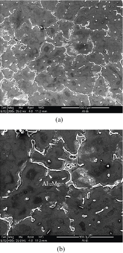
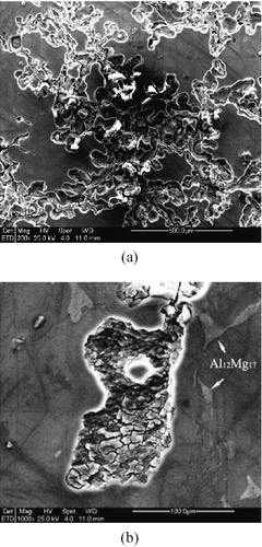
A magnesium AZ91D ingot in the as-cast condition was used in the investigation. Its nominal composition is shown in table 1. Sample plates of 5 mm thickness were machined from the ingot for laser processing. The matrix of AZ91D is α-Mg solid solution, as shown in figure , in which γ-Mg17Al12 intermetallic compounds segregated along grain boundaries, with some eutectics distributed nearby. The alloying material is a commercial Al-12 wt.% Si alloy powder with particle size of 80–180 μm.
Nominal compositions of magnesium alloy AZ91D (wt.%).
Figure 1 Microstructures of as-cast magnesium alloy AZ91D. (a) Matrix α-Mg solid solution with segregated γ-Mg17Al12 IMCs along grain boundaries and (b) grain boundary γ-Mg17Al12 and some eutectics.
A 2500 W Nd:YAG laser (Rofin CW 025) robot system was used for the laser alloying. The laser beam was delivered to the alloying site through an optical fiber (0.6 mm in diameter) fixed on the robot arm, parallel to the normal of the plates. The focal length of the focal lens was 200 mm. Defocused beam was used in the alloying with a beam spot of 4 mm diameter. The ranges of laser powers and translation speeds were 1000–1400 W and 300–550 mm min−1, respectively.
Blown-powder laser surface alloying was applied using a PC-controlled powder feeder. A concentric, double-tube nozzle was used for powder feeding and argon shielding, whose diameters of the inner and outer shield tubes were 4 and 11 mm, respectively. The nozzle was set at 45° relative to and in front of the laser beam, delivering the argon shielded powder at a powder flow rate range of 2.9–3.9 g min−1 and an argon flow rate range of 10–18 l min−1.
Before alloying, the surface of sample plates was sand-blasted in order to enhance the absorption of laser energy. After alloying, the samples were sectioned in the transverse direction, then molded in resin, ground and polished to a mirror finish. Nital is used to reveal the microstructures of interest. Metallographic samples were examined using both an Olympus-SZ61 optical microscope and a Phillips XL-30 SEM equipped with EDS. The hardness of the alloyed specimens was measured using a micro-hardness tester, FUTURE-TECH FM-700, at a load of 50 g and a load time of 30 s. A D8 Advance x-ray diffractometer with CuKα radiation was used to identify phases in the alloyed metal.
The corrosion performance of both the AZ91D matrix and alloyed layers was evaluated by applying anodic polarization test [Citation15]. Corrosion samples were taken from overlapped layers of multiple alloyed passes, whose exposed area is 1 cm2. The samples were mounted in epoxy resin, and then metallographically prepared to a mirror finish. The corrosion medium was 3.5 wt.% NaCl aqueous solution of analytical grade. The constant-potential instrument M273A coupled with the corrosion measurement software M352 were used for the test. The initial temperature of the solution was room temperature (20 °C). The potentiodynamic polarization plots were produced at a scanning rate of 1.0 mV s−1. All potentials were measured with reference to a standard calomel electrode (SCE).
Results and discussion
Microstructure characteristics
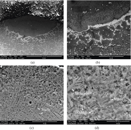
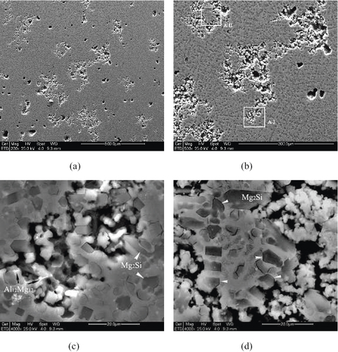
The laser alloying of AZ91D with Al–Si powder was performed using the given laser parameters. The typical morphology of the alloyed layers is shown in figure (a). Note that the interface between the alloyed layer and the base metal exhibits metallurgical bonding. It was further observed that the heat-affected zone of the alloyed layer is narrow, where some IMC γ-Al12Mg17 clearly liquified and resolidified owing to the rapid heating by the laser scanning (figure (b)). In the melt, various alloyed phases featuring dendrites and angular particles were formed (figures (c) and (d)). EDS detection primarily revealed that the dispersed, darker dendritic phase is Mg2Si, whereas the compact, lighter dendritic and angular phases are either Al12Mg17 or Al3Mg2 (figure (d)). It is evident that the microstructure of the alloyed layers markedly differs from that of AZ91D.
Figure 2 Morphology and microstructure of alloyed AZ91D layer: (a) transection view; (b) narrow HAZ and liquified γ-Al12Mg17 IMCs; (c) dendritic and angular IMC phases; (d) upper region of (c) featuring compact structure of phases.
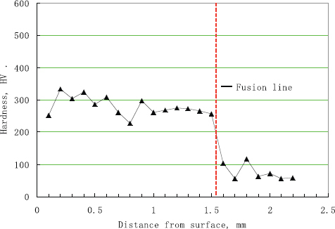
Hardness test was performed on the alloyed layers to verify alloying effects. The results show that the hardness of the Al–Si alloyed layers is much higher than that of the AZ91D base metal. A typical hardness plot in the depth direction of the alloyed layers is shown in figure . It can be seen that the hardness of the alloyed layers varies from 220 to 340 Hv, with a decreasing trend towards the layer depth direction, except for a lower hardness near the surface. This evidently is attributed to the type and distribution density of the IMC phases formed in the alloyed layers, as shown in figure . At the fusion line, hardness drops abruptly. However, there is still certain hardening in the HAZ, which could be due to the combined effect of resolidified interfacial IMCs and the possible element diffusion. The hardness then tends to be stable at a low level in the base metal.
Figure 3 Hardness distributioin of laser-alloyed AZ91D layer with Al–Si.
XRD analysis was conducted to identify the alloyed phases using the specimens prepared from overlapping alloyed layers produced with the 1.1×10⁴ W cm−2 laser power density, 300 mm min−1 translation speed and 40% overlapping rate. The specimens for XRD analysis were ground and polished by conventional metallography.
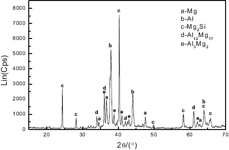
Figure shows the XRD spectrum of the Al–Si alloyed AZ91D layers. Various IMCs such as Mg2Si, Al12Mg17, Al3Mg2 and solid solutions of α-magnesium and aluminum were identified. This clearly shows the laser alloying effect of Al–Si powders on the magnesium alloy. It is also observed that there are multiple diffraction peaks of the respective planes of the phase Mg2Si in the spectrum. The higher intensity of Mg2Si peaks qualitatively signifies a higher concentration of Mg2Si phase in the alloyed layer, which corresponds to the dispersed darker dendritic phase (figure ). Note that the phase Mg2Si takes a dendritic form in the alloyed microstructure rather than a particle form in two-step laser-clad microstructures [Citation7]. Based on the compositions of both AZ91D (table 1) and Al–Si powders, it is not difficult to see that Si comes from the Al–Si powder. Besides, note that there are no diffraction peaks of Si and Zn in the XRD spectrum, and that a slight Bragg peak shift of Al occurred. It can therefore be deduced that Si mainly interacts with Mg to form the Mg2Si phase, and that there might be limited Si, together with Zn, dissolved in the Al lattice inducing lattice distortion. Furthermore, no metastable compounds composed of aluminum and magnesium were detected in such rapidly solidified microstructure generated by laser alloying.
Figure 4 XRD spectrum of laser-alloyed AZ91D layer with Al–Si powder.
Corrosion behaviors
Anodic polarization test was conducted using samples from the overlapped Al–Si alloyed layers and AZ91D, under the previously described experimental conditions. The typical dynamic potential anodic polarization plot achieved is shown in figure . The dynamic polarized corrosion potential (Ecorr) and corrosion current (Icorr) are also shown in the plot based on the calculation of the cross point of the anode and cathode Tafel curves. It is seen that the corrosion potential of the alloyed layers is 435 mV higher and the corrosion current is one order of magnitude less than that of AZ91D. This indicates that Al–Si alloyed layers possess a low corrosion rate and a high polarization resistance[Citation13, Citation15]. It could be assumed that the compactly dispersed Mg2Si, γ-Al12Mg17, β-Al3Mg2 played a role in increasing corrosion resistance on the basis of results of the previous microstructure characterization and XRD analysis. As these IMCs possess higher potentials relative to that of magnesium, it is reasonable to expect increased corrosion potential in the Al–Si alloyed microstructure.
Figure 5 Polarization curve of Al–Si alloyed layers and AZ91D in 3.5 wt.% NaCl solution.

To further identify the corrosion resistance effects of the IMC phases, the corrosion characteristics of the corroded samples was investigated. Figure 6 shows the corrosion features on the surface of the AZ91D base metal, where preferential corrosion is notable (figure (a)). Further observation showed that the corrosion attack preferentially occurred in the matrix of α-magnesium solid solution (figure (b)), where the grain boundary γ-Al12Mg17 shows no liable sites for corrosion. Such a phenomenon could be simply explained by the effect of microgalvanic coupling between the cathodic γ-phase and the anodic α-Mg matrix [Citation10]. In addition, some hollow sites suggest the falling off of the γ-Al12Mg17 phase (on left of figure (a), which indicates the possible relationship between corrosion characteristics and preferential corrosion in the matrix.
Figure 6 Corrosion features of AZ91D base metal in 3.5% NaCl solution: (a) preferential corrosion sites and (b) preferential attack at α-magnesium solid solution leaving grain boundary γ-Al12Mg17 unattacked.
The corrosion features of the Al–Si alloyed layers of AZ91D are shown in figure . It is evident that the corrosion attack selectively occurred on the tested surface. Comparing figure (a) with figure (a) at the shown comparable magnification, it is clear that the alloyed layers exhibit a weak corrosion attack. Figure 7(b) further shows localized features of corrosion, in which the corrosion characteristics at locations A-I and A-II are shown in figures (c) and (d). It is evident that preferential corrosion occurred and propagated in the matrix composed of α-Mg and Al solid solutions, without attacking dense IMC particles. Meanwhile, there are some concaves obviously caused by the falling off of IMC particles, which are similar to the case of AZ91D base metal.
Figure 7 Corrosion features of Al–Si alloyed AZ91D layer in 3.5% NaCl solution. (a) General view; (b) central area of (a); (c) details of A-I showing preferential attack at matrix of α-Mg and Al solid solution; (d) details at A-II showing early interfacial attack at the interface of IMCs (arrows).
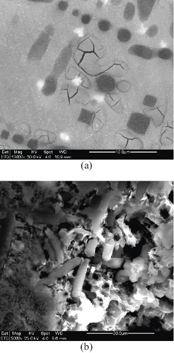
Further observation showed that the early attack proceeded in microgrooves. On one hand, microgrooves occurred at interfaces between IMCs and the matrix (figures (c) and (d)). On the other hand, the corroded microgrooves were also observed in some substructures of the matrix, leaving such IMCs as Mg2Si, γ-Al12Mg17 and Al3Mg2 unattacked (figure (a)). It can be assumed that once the microgrooves interconnect in the matrix, the microstructure would be readily dissolved by leaving concaves. This is evidenced in regions where prominent corrosion occurred, as shown in figure (b). It can be seen that some dendritic IMC phases hanging over corroded concaves as corrosion pervaded in the alloyed microstructure, which suggests the corrosion resistance of IMCs. It can therefore be confirmed that corrosion proceeded as early microgrooves that pervaded the matrix by interconnection formed corroded concaves, causing IMC phases to become unsupported, and hence fallen-off, which finally resulted in an expanded corrosion volume in the microstructure.
Figure 8 Preferential corrosion of Al–Si alloyed AZ91D microstructure. (a) Corroded microgrooves in substructures of matrix (lighter particles are either Al12Mg17 or Al3Mg2). (b) IMC phases hanging over corroded concave matrix.
From the results of the anodic polarized test and microstructure investigation, it can be understood that the IMCs in the Al–Si alloyed layers are important constituents resistant to corrosion attack in Cl− corrosion medium. This result conforms with other observations that Mg2Si [Citation7], γ-Al12Mg17 [Citation4, Citation7], β-Al3Mg2 [Citation10] are corrosion-resistant constituents. It is these dense IMCs in the microstructure that actually constitute a 3D corrosion-resistant barrier network that retards corrosion, by increasing polarized corrosion potential and decreasing corrosion current. However, no minute difference in corrosion resistance between the Mg2Si, γ-Al12Mg17 and Al3Mg2 phases was observed in this experiment. Further work is needed to confirm such difference.
Conclusions
Excellent alloyed layers of metallurgical bonding were achieved in the laser alloying of AZ91D with Al–Si powder. A compactly dispersed dendritic phase of Mg2Si, and dendritic and angular phases of Al12Mg17 or Al3Mg2 were formed in the matrix of mixed α-Mg and Al solid solutions in the Al–Si alloyed layers. | |||||
For the alloy AZ91D base metal, corrosion preferentially occurred at the α-Mg matrix. The grain boundary Al12Mg17 is corrosion-resistant in 3.5% NaCl aqueous solution. AZ91D laser-alloyed Al–Si layers exhibited improved corrosion resistance. The IMCs of Mg2Si, γ-Al12Mg17 and Al3Mg2 in the Al–Si alloyed layers are the constituents contributing to such resistance. | |||||
Corrosion was observed to initiate at the interface between IMCs and the solid solution matrix, and at substructures of the matrix of the Al–Si alloyed layers. The early corroded microgrooves penetrated into the matrix by interconnection, which resulted in corroded concaves, causing compact IMCs to become unsupported and fallen off, hence breaking the corrosion-resistant barrier of IMC phases, yielding an enlarged corrosion volume in the microstructure. | |||||
Acknowledgment
The authors are grateful to Beijing Education Committee for financial support from Foundation of Science and Technology.
References
- RaynorG V 1959 The Physical Metallurgy of Magnesium and its Alloys London Pergamon p 1
- MordikeB LEbertT 2001 Mater. Sci. Eng.A 302 37 http://dx.doi.org/10.1016/S0921-5093(00)01351-4
- GrayJ ELuanB 2002 J. Alloys Compound 336 88 http://dx.doi.org/10.1016/S0925-8388(01)01899-0
- GalunRWeisheitAMordikeB L 1996 J. Laser Appl. 8 299
- SubramanianRSircarSMazumderJ 1991 J. Mater. Sci. 26 951
- WangA ASircarSMazumderJ 1993 J. Mater. Sci. 28 5113 http://dx.doi.org/10.1007/BF00570050
- YueT MWangA HManH C 1999 Scr. Mater. 40 303 http://dx.doi.org/10.1016/S1359-6462(98)00416-3
- YueT MHuQ WMeiZManH C 2001 Mater. Lett. 47 165 http://dx.doi.org/10.1016/S0167-577X(00)00230-5
- YueT MMeiZManH C 2001 J. Mater. Sci. Lett. 20 1479 http://dx.doi.org/10.1023/A:1017966111324
- AungN NZhouW 2002 J. Appl. Electrochem. 32 1397 http://dx.doi.org/10.1023/A:1022698916817
- IgnatSSallamandPGreveyD 2004 Appl. Surf. Sci. 225 124 http://dx.doi.org/10.1016/j.apsusc.2003.09.043
- MeiaZGuoL FYueT M 2005 J. Mater. Process. Technol. 161 462 http://dx.doi.org/10.1016/j.jmatprotec.2004.07.084
- MajumdaraJ DGalunRMordikeB LMannaaI 2003 Mater. Sci. Eng. A 361 119 http://dx.doi.org/10.1016/S0921-5093(03)00519-7
- 1992 Alloy Phase Diagrams, ASM Handbook vol 3 ASM International
- ASTM G3-89 (Reapproved 2004), Standard Practice for Conventions Applicable to Electrochemical Measurements in Corrosion Testing.