Abstract
Microcapsules were prepared by in situ polymerization and microcapsulation. Tetraethyl orthosilicate was used as the core material and phenolic resin was used as the wall material in an emulsion system of polyacrylic and tetraethyl orthosilicate. The obtained microcapsules were slowly heated such that the core material was released by evaporation, leaving hollow-core spheres. The spheres were mixed with a phenolic resin-derived binder and molded to obtain a carbon foam precursor, which was carbonized at 1100 °C under the protection of N2 gas and graphitized at 2300 °C under the protection of Ar gas. Thus, the carbon foam of hollow closed-shelled microspheres with a graphitic structure was prepared. The properties and structure of this foam were discussed.
Introduction
Carbon foam is a new material with excellent properties [Citation1]. It falls into two types in terms of its structure. One is characterized by a cellular structure. With its open-celled structure and ligament carbon fiber structure, it has a high thermal conductivity and is an ideal material for radiator-type devices [Citation2–7]. The other is characterized by a hollow microspheric structure. This material exhibits a low thermal conductivity and a high specific strength. Hence, it can be used for thermal insulation and ablation resistance. As a functional material, it is expected to find a wide range of applications in nuclear energy technology, aerospace industry, automobile and ship industries, and architectural engineering [Citation8–11].
Bruneton et al [Citation12] heated a phenolic resin to convert it into a liquid or viscous product. At a specific heating rate, they transformed the liquid or viscous product into hollow individual spheres, which were bound with the binder fabricated from the phenolic resin and molded. The foam was carbonized to prepare a type of carbon foam. However, the spheres obtained in this manner are open-celled, uneven in wall thickness and poor in sphericity. Therefore, their heat tolerance and thermal resistance should be improved for heat insulation.
Microcapsulation is enwrapping a solid or liquid with a film material to produce microparticles [Citation13, Citation14]. Such microparticles have many unique properties. They are widely used in food and drugs, phase-changing materials, nano science and technology, and other fields [Citation15–17]. In this work, hollow phenolic resin spheres were prepared with a linear thermosetting phenolic resin as the main material using a method involving in situ polymerization and microcapsulation. Microcapsules were bound and molded to get a carbon foam precursor. Then the precursor was carbonized and graphitized to obtain good carbon foam of hollow spheres.
Experimental procedure
Forty milliliters of tetraethyl orthosilicate (TEOS), 90 ml of polyacrylic acid (PAA) and 600 ml of water were placed in a 1000 ml three-mouthed flask equipped with a reflux condensation tube, a stirrer and a thermometer. The mixture was stirred rapidly to form a dispersed emulsion system. The system was then heated to 40 °C in a water bath. Then small amounts of resol prepolymer and resorcinol were added slowly with stirring at a constant rate of 1000 rpm. Moreover, 10 ml of 8 mol L−1 urotropine was added. The pH of the mixture was adjusted to 2–3 by adding 6 mol L−1 HC1, and the mixture was heated to 90 °C. Thus, TEOS-in-phenolic resin spheres were obtained. The spheres were slowly heated so that the TEOS in the core was released by evaporation, leaving the spheres with hollow cores. The spheres were bound with the phenolic resin-derived binder and molded to produce the carbon form precursor, which was then carbonized at 1100 °C under the protection of N2 gas and graphitized at 2300 °C under the protection of Ar gas. The prepared carbon foam was that of hollow closed-shelled microspheres with a graphitic structure. The thermal physical performance of the foam was tested by a laser pulse method.
Results and discussion
Formation mechanism of microcapsules
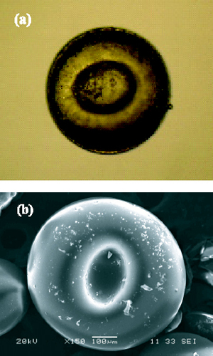
The formation of microcapsules involves three steps. The first step is emulsion dispersion. The oily TEOS is added to the anionic surfactant—PAA-water solution—to obtain a dispersed emulsion. This is a typical surfactant/oil/water (SOW) emulsion with oil emulsified in water with the aid of the surfactant. In this process, PAA is an anionic surfactant with a wide range of molecular chain lengths. PAA aqueous solution with an appropriate polydispersity is selected to make sure that the partition ratio (Kp) of PAA in water and oil is less than 1. The strain direction of the oil–water interfacial membrane turns into the oil phase and a stable water-in-oil (O/W) emulsion is formed. Then, the oleophilic functional group of PAA in the emulsion tends to turn into the oil phase (inside the emulsified drop), while the hydrophilic functional group tends to turn into the water phase (outside the emulsified drop). The hydrophilic functional group of PAA is the carboxyl group with a negative charge, and a linear thermosetting phenolic resin, when added to the emulsion system, can agglomerate around the emulsion drop under eletrostatic interaction to form microcapsules because the chain ends of the linear phenolic resin are positively charged. Additionally, such agglomeration may be related to the viscous linear phenolic resin. Finally, a crosslinking agent (resorcin), a firming agent (hexamethylene tetramine) and resol are added for further in situ aggregation, crosslinking and solidification to convert resol into resitol (reticulation) or resite (body shape), producing microcapsules of TEOS-in-phenolic resin solid particles. Most of the PAA molecules break away from the oil phase of the emulsified drop and gradually enter the water phase during either agglomeration or solidification. The core of the microcapsules has an oil phase component, the majority of which is TEOS. Figures (a) and (b) show the digital photograph and SEM image of the TEOS-in-phenolic resin capsule.
Figure 1 (a) Digital photograph of microcapsule. (b) SEM image of microcapsule.
Formation mechanism of hollow phenolic resin spheres
Microspheres with TEOS wrapped in the phenolic resin are obtained by releasing the core material through evaporation. The spheres are characterized with hollow cores and closed shells. TEOS is a lipoid with a low boiling point (168 °C). The phenolic resin is thermoset. When the microcapsules are heated at a specific rate to 160–240 °C, TEOS is completely evaporated, resulting in the microspheres with hollow cores and closed shells.
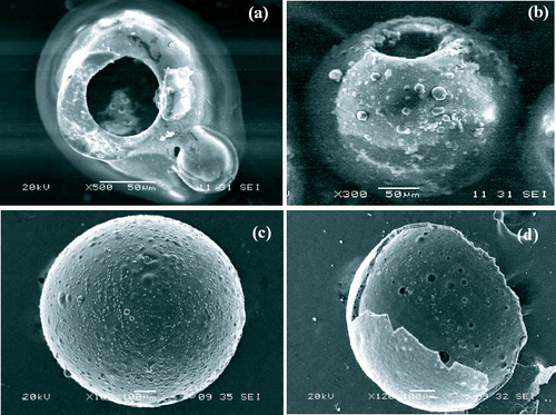
The heat treatment temperature and heating rate are directly related to the formation of the hollow phenolic resin spheres. If both are high, TEOS will leak through the capsule wall rapidly, leaving the hollow spheres. A pore is observed in a hollow sphere with an overturned cover, as shown in figure (a). If the heat treatment temperature remains contant and the heating rate decreases, TEOS will be evaporated slowly, leaving the hollow sphere with a pore, as shown in figure (b). When the temperature is moderately high but the heating rate is very low, the capsule wall, namely, the thermoset phenolic resin, becomes loose and TEOS will leak uniformly through the loose wall. Thus, no overturned cover or open hole is formed. The perfect hollow spheres with closed shells are produced, as shown in figure (c). Figure (d) shows the morphology of a broken sphere with a hollow core and a thick wall.
Figure 2 (a) SEM image of hollow phenolic resin sphere with pore with overturned cover at high temperature and high heating rate. (b) SEM image of hollow pored phenolic resin sphere at moderately high temperature and relatively high heating rate. (c) SEM image of hollow phenolic resin sphere with closed shell at reasonably high temperature and low heating rate. (d) SEM image of broken hollow phenolic resin with thick wall.
Morphology and structure of hollow carbon microspheres with closed shells
The phenolic foam is widely used in the fields of thermal engineering works, ships and automobiles. However, it cannot bear a temperature over 400 °C. When it turns into a material with a graphitic structure, it can resist high temperatures apparently. The direct graphitization of hollow phenolic resin microspheres with closed shells may affect the morphology of the spheres since the phenolic resin contains certain amounts of non-carbon elements, such as H and O. Therefore, the phenolic resin spheres are carbonized at 1100 °C in the case of N2 protection and then graphitized at 2300 °C in the case of Ar protection. Thus, carbon microspheres that consist mainly of graphitic crystals are obtained. The microspheres can bear the heat of 1200 °C and can be used for heat insulation in aerospace.
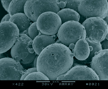
Carbonization is a process in which phenolic resin spheres, the precursor of carbon foam, are converted into carbon spheres. In this process, the decomposition of carbon chains, as well as carbonization, occurs. Only a properly controlled process can produce carbon spheres with a perfect morphology. Figure shows the SEM images of four carbon microspheres obtained under different conditions. If N2 is not sufficiently pure or there is a slight leakage of air in the carbonizing furnace, the surface of the hollow phenolic resin spheres will be oxidized and will become rough, as shown in figure (a). When the heating rate is low but the cooling rate is high, a rapid contraction of the spheres results in the formation of microspheres with a poor shape, as shown in figure (b). When the heating rate is too high, cracks are formed on the surface of the spheres, as shown in figure (c). By slow heating and cooling, perfect carbon spheres can be obtained, as shown in figure (d). The morphology of the final carbon foam consisting of hollow closed-shelled spheres is shown in figure .
Figure 3 (a) SEM image of carbon sphere with oxidized and rough surface due to impure N2 or slight leakage of air in furnace. (b) SEM image of carbon sphere with poor shape at low heating and high cooling rates. (c) SEM image of carbon sphere with cracks on its surface at high heating rate. (d) SEM image of carbon sphere with perfect morphology by slow heating and cooling.
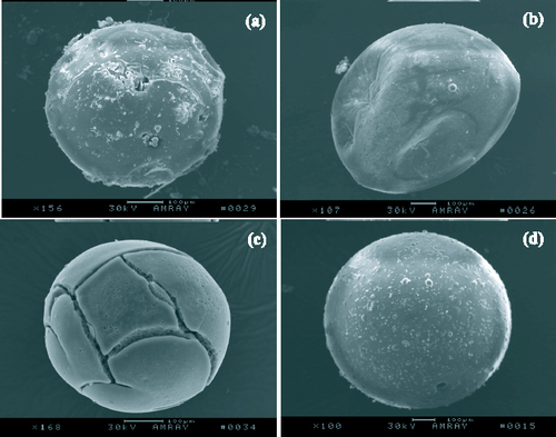
Figure 4 SEM image of carbon foams.
NETZSCH 409C was used for heat analysis. The measurement temperature ranged from room temperature to 1300 °C, the protective gas was air, and the flow rate of the gas was 1 ml min−1. The obtained thermogravity curves of the phenolic resin sphere precursor (-PF-) and the graphitization (-2300-) product are shown in figure . It can be seen in this figure that graphitization apparently improved the oxidation resistance of the carbon foam. It can also be seen that the gravity increases slightly between 400 and 900 °C owing to the marked decrease in the rising force of the gas flow.
Figure 5 TG curves before and after graphitization.
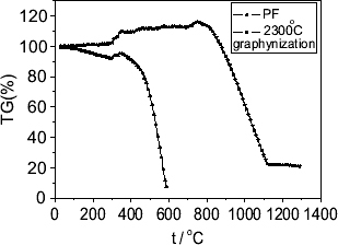
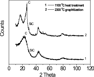
Figure shows the XRD diagrams of the hollow phenolic resin spheres with closed shells carbonized and graphitized at different temperatures. The increasing heat treatment temperature increased the content of the graphitized crystal such that one sharp peak appeared, indicating that the oxidation resistance of the carbon foam was improved. Moreover the weak peak generated by SiC was observed. This is because TEOS was used in the preparation of the carbon foam. After a series of heat treatments, TEOS was converted into SiC, which made a little contribution to the oxidation resistance of the carbon foam.
Figure 6 XRD diagrams of carbon foam treated at different temperatures.
Thermal physical properties of hollow carbon microspheres with closed shells
The core of the sphere is almost vacuum. Each hollow sphere in the carbon foam is a thermally resistant cell. Therefore, the carbon foam made of such spheres has a low thermal conductivity. The thermal properties of carbon materials are tested on a heat determinator (TC-3000, Shimadzu) by a laser pulse method. Results show that the prepared carbon foam has a lower thermal conductivity than the carbon/carbon composites. Therefore, it can be concluded that the carbon foam is an ideal material for thermal insulation and ablation resistance. Table 1 shows the thermal properties of a typical carbon/carbon composite and carbon foams with different densities.
Thermal properties of C/C composite and carbon foams of different densities at various temperatures.
Conclusions
Phenolic resin microcapsules have been prepared by in situ polymerization and microcapsulation. The core material of the microcapsules was slowly released by evaporation, leaving hollow close-shelled spheres of uniform particle size, perfect sphericity and homogeneous wall thickness. The hollow phenolic resin spheres were mixed with a phenolic resin-derived binder and molded to obtain a carbon foam precursor. Then the carbon foam of hollow close-shelled spheres with a graphitic structure was obtained by carbonization and graphitization. The thermal conductivity coefficient of the foam was low.
Acknowledgments
This work was supported by the National ‘973’ project (Grant No 2006CB600908). The cooperation of our partners in the C/C Composites Technology Research Center of NPU in China is acknowledged.
References
- ThomasBKhalidLAhmedE 2005Carbon431055 http://dx.doi.org/10.1016/j.carbon.2004.11.046
- MaruyamaBSpowartJ EHooperD JMullensH MDrumaA MDrumaCAlamM K 2006Scr. Mater.541709 http://dx.doi.org/10.1016/j.scriptamat.2005.12.060
- WangXZhongJWangYYuM 2006Carbon441560 http://dx.doi.org/10.1016/j.carbon.2005.12.025
- KlettJHardyRRomineEWallsCBurchellT 2000Carbon38953 http://dx.doi.org/10.1016/S0008-6223(99)00190-6
- MehtaRAndersonD PHagerJ W 2003Carbon412159 http://dx.doi.org/10.1016/S0008-6223(03)00243-4
- GallegoN CKlettJ W 2003Carbon411461 http://dx.doi.org/10.1016/S0008-6223(03)00091-5
- MaslovKKinraV K 2004Mater. Sci. Eng.A 36789 http://dx.doi.org/10.1016/j.msea.2003.09.088
- FilhoC AZarbinA J 2006Carbon442869 http://dx.doi.org/10.1016/j.carbon.2006.06.002
- StillerA HStansberryP GZondloJ W 1999US Patent5888469
- InagakiMMorishitaTKunoAKitoTHiranoMSuwaTKusakawaK 2004Carbon42497 http://dx.doi.org/10.1016/j.carbon.2003.12.080
- KwonY WYoonS HSistareP J 1997Compos. Struct.38573 http://dx.doi.org/10.1016/S0263-8223(97)00093-7
- BrunetonETallaronCGrass-NaulinNCosculluelaA 2002Carbon401919 http://dx.doi.org/10.1016/S0008-6223(02)00003-9
- HerreroE PValleE MGalánM A 2006Chem. Eng. J.117137 http://dx.doi.org/10.1016/j.cej.2005.12.022
- BrownE NWhiteS RSottosN R 2005Compos. Sci. Technol.652466 http://dx.doi.org/10.1016/j.compscitech.2005.04.020
- HongKParkS 1999Mater. Sci. Eng.A 272418 http://dx.doi.org/10.1016/S0921-5093(99)00509-2
- TeixeiraM IAndradeL RFarinaMRocha-LeãoM H 2004Mater. Sci. Eng.C 24653 http://dx.doi.org/10.1016/j.msec.2004.08.008
- HawladerM NUddinM SKhinM M 2003Appl. Energy74195 http://dx.doi.org/10.1016/S0306-2619(02)00146-0