Abstract
The USS Emmons, a 106m US Navy Gleaves‐class destroyer minesweeper that sank in 40m of water off Okinawa Island, Japan after kamikaze attack in 1945, is used as a case study for examining the history, multivocal significance, and heritage management of a World War II naval battle site. A baseline record of the site was made using an innovative method incorporating precise control points obtained from high‐resolution multibeam echosounding bathymetry to generate 3D models using structure‐from‐motion photogrammetry. The 3D models produced can be used for sharing information about this underwater cultural heritage and for future in situ monitoring of the archaeological remains.
Abstracto
Evaluación e importancia de un sitio de batalla de la Segunda Guerra Mundial: registrando el USS Emmons mediante Modelos Digitales de Elevación (MDE) de alta resolución que combinan batimetría multihaz y fotogrametría de Estructura a partir del Movimiento (SfM)
El USS Emmons, un destructor dragaminas de la clase Glaves de la marina estadounidense (US Navy) que se hundió a 40 m de profundidad en la Isla de Okinawa en Japón, tras un ataque kamikaze en 1945, se utiliza como estudio de caso para examinar la historia, la importancia multivocal y la gestión del patrimonio de un yacimiento de batalla naval de la Segunda Guerra Mundial. Se llevo a cabo un levantamiento con línea base, empleando un método innovador que incorpora puntos de control precisos obtenidos mediante una batimetría elaborada con una ecosonda multihaz de alta resolución, para generar modelos 3D mediante fotogrametría de estructura a partir del movimiento. Los modelos 3D que se elaboraron pueden ser usados para compartir información sobre este patrimonio cultural sumergido y, también, para el futuro monitoreo in situ de los restos arqueológicos.
Palabras Clave: Ecosonda multihaz, fotogrametría de Estructura a partir del Movimiento (SfM), visualización 3D, Okinawa, Islas Ryukyu, US Navy
抽象
第二次世界大戦遺跡の評-と意義: マルチビ-ム測深と多視点ステ-オ写真測量を組み合わせ-作成した
高解像度数値地形モデ-を用いた米国戦艦エモンズの-録
本論-は第二次世界大戦の海戦跡にお-て, 戦史や遺-の多義的な-要性お-び水中文化遺産の管理につ-て検討-た。研究対象は沖縄・古宇利島沖の水深40mに沈む全長106mの米国軍艦エモンズで-る。エモン-は第二次大戦末期の沖縄戦にお-て、日本軍特攻機の攻撃によっ-航行不能と-り, 僚艦によ-て沈めら-た。本研究では, 高精度マルチビーム-響測深から得られ-位置情報を多視点ステ-オ写真測量によ-三次元モ-ル生成に使用すると-う革新的な方法によ-て, きわめ-詳細な遺-の基図を作成した。こ-三次元モデ-は水中文化遺産の情報共有や今後の遺物・遺物の保全に有用で-る。
キーワ-ド: マルチビ-ム測深, 多視点ステ-オ写真測量,三次元可視化, 沖縄, 琉球列島, 米国海軍
摘要
对一处二战遗址的评估及其意义:多波束测深与SfM摄影测量相结合对美国海军埃蒙斯号 (USS Emmons) 的高分辨率DEM记录
埃蒙斯号 (USS Emmons) 是一艘-106米的美国海军格里维斯级鱼雷驱-舰, 1945年遭日本神风特攻队攻击, 沉没于冲绳岛外40米深的海域。该遗址一直作为审视二战海战的历史、多重意义和遗产管理的研究案例。这-遗址基础数据的收集采用了一种革新方法。该方法包括使用高分辨多波束测深获得精确控制点, 并根据运动推断结构摄影测量法生成3D模型。这些制作好的3D模型不仅可用于分享-一水下文化遗产的信息, 未来还可用于对考古遗-进行原地监测。
對一-二戰遺址的評估及其意義:多波束測深與SfM攝影測量相結合對美國海軍埃蒙斯號 (USS Emmons) 的高分辨率DEM-錄
埃蒙斯號 (USS Emmons) 是一艘-106米的美國海軍格裏維斯級魚雷驅-艦, 1945年遭日本神風特攻隊攻擊, 沉沒于沖繩島外40米深的海域。該遺址一直作爲審視二戰海戰的歷史、多重意義和遺産管理的研究案例。這-遺址基礎數據的收集采用了一種革新方法。該方法包括使用高分辨多波束測深獲得精確控制點, 並根據運動推斷結構攝影測量法生成3D模型。這些制作好的3D模型不僅可用于分享-一水下文化遺産的信息, 未來還可用于對考古遺-進行原地監測。
關-詞:多波束測深儀, SfM攝影測量, 3D可視化, 沖繩島, 琉球諸島, 美國海軍
ملخص
While countless witnesses have provided vivid accounts of their World War II (WWII) experiences since it ended more than 70 years ago, documentation of the war through material evidence is increasing in significance. We need to consider the historical significance of the material remains of WWII and determine how to preserve them for posterity. The remains of WWII naval battle sites can be found under water (Monfils et al., Citation2006). Some WWII wrecks have been surveyed at Pearl Harbor, Hawaii (Lenihan et al., Citation1989: 192; Stone, Citation2003: 80), Chuuk Atoll, and the Federated States of Micronesia (Jeffery, Citation2004; Citation2007, Citation2012); however, most have not yet been subject to archaeological investigation. WWII battle sites will be covered by the 2001 Convention on the Protection of the Underwater Cultural Heritage (UNESCO, Citation2002) from 2039, thus it is necessary to formulate policies for their preservation. To assess the level of preservation of wreck‐sites for both management and future archaeological study, it is necessary to create visualizations based on quantifiable data using scientific techniques of the wrecks themselves and their environments.
This study aims to produce precise geographic information for the preservation, long‐term research, and future use of a historically important WWII battle site on the seafloor off the coast of Okinawa, Japan. Then we intend to discuss the different roles of WWII Underwater Cultural Heritage, and the multivocal significance of the site. We first surveyed seafloor bathymetry over a wide area using a multibeam echosounder to observe geomorphological, sedimentological, and oceanographic conditions around the site. Then, to produce an ultra‐high‐resolution bathymetric map of ∼0.05m grid size for the site and remains, we developed a novel methodology that combines structure‐from‐motion (SfM) photogrammetry with multibeam bathymetry.
The locations and shapes of sites on land can be accurately recorded using aerial photography and large‐scale topographic maps. The development of such mapping has benefitted significantly from remarkable improvements in the precision of satellite‐based positioning systems, such as global positioning system (GPS), differential GPS, and real‐time kinematic (RTK) positioning systems. Recent progress in photogrammetric technology due to SfM photogrammetry allows us to capture highly precise and accurate three‐dimensional (3D) shapes (see Ducke et al., Citation2011; Verhoeven et al., Citation2012: 145). Recording technology for 3D objects using photogrammetry is also developing rapidly, as it is becoming increasingly important for conservation technologies (Guidi et al., Citation2014) and aiding in cultural heritage‐related activities such as exhibitions (De Reu et al., Citation2013; Liritzis et al., Citation2015). Surveys using unmanned aerial vehicles (UAVs) combined with SfM photogrammetry enable us to generate accurate and precise digital elevation models (DEMs) that represent 3D surface elevation data (x, y, and z) of topography. By producing DEMs and large‐scale maps of a given area, UAV–SfM mapping can be used to record archaeological sites (Balletti et al., Citation2015).
The construction of 3D SfM models also allows for a detailed and objective description of underwater archaeological sites (Mertes et al., Citation2014; Yamafune et al., Citation2016). Remotely operated vehicles (ROVs) are also used for underwater photogrammetric surveys of wrecks (Nornes et al., Citation2015). Despite advancements in technologies that can be used to generate underwater 3D SfM models, these models are not constructed on geographical coordinate systems because satellite positioning technology cannot be directly used at depth. Mapping by using geographical coordinates is possible only for very shallow seafloors, where satellite positioning at sea level can be used (Henderson, Citation2013).
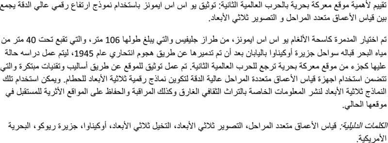
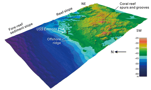
In this study, we report a novel attempt to eliminate the above problem by incorporating precise control points obtained from high‐resolution multibeam echosounding bathymetry to generate underwater 3D models with geographical coordinates (that is an ultra‐high‐resolution bathymetric map with texture information) using SfM photogrammetry. An underwater 3D model was created for USS Emmons, a 106m‐long battleship that now lies at a depth of 40m north‐east of Kouri Island in Okinawa, Japan (Fig. 1).
USS Emmons in the Battle of Okinawa
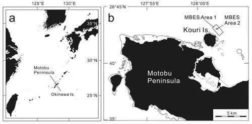
USS Emmons was a Livermore‐class (or Gleaves‐class) destroyer built by the Bath Iron Works Corp. in Bath, Maine in the United States (Mooney, Citation1963). It was laid down on 14 November 1940 and was launched on 23 August 1941. It was commissioned as a DD–475 destroyer on 5 December 1941 (Wilde, Citation2001: 145; Billingsley, Citation2005). Afterward, it was converted into a high‐speed destroyer minesweeper (DMS–22) while docked in Boston in 1944 (Billingsley, Citation2005: 303). The ship (Fig. 2) had a displacement of 1630 tons, was 106.17m long (348 feet 4 inches) and 11m wide (15 feet 8 inches), and had a biaxial motor of 50,000shp (37MW) and a maximum speed of 38 knots (70km/h). Its complement was 208 and 276 in wartime.
Emmons was in company with USS Rodman (DMS21), which at that time, was the senior ship. They approached Okinawa on 23 March 1945, and began sweeping Okinawa on 24 March 1945 (Billingsley, Citation2005: 318). Based on the Action Report of USS Emmons from April 1945 (Griffin, Citation1945), Emmons was on radar picket duty in the north‐west of Okinawa, serving to find and report enemy aircraft. On 6 April, it was at the action station together with Rodman (DMS–21), and was targeted by massive suicide aircraft attacks by kamikaze. At around 15:15 hrs (local time), having observed two Japanese aircraft nearby, one plane crashed into Rodman’s forecastle. When Rodman was attacked, Emmons began circling it and tried to provide fire support to protect it. However, numerous Japanese planes appeared and a dog fight ensued between 50 Japanese planes and the Combat Air Patrol. While supporting Rodman, Emmons also became the target of attack. Though Emmons shot down six planes, it was attacked by five aircraft almost simultaneously. Four other attacks missed Emmons by only a few yards.
The first hit on Emmons was recorded as at 17:32 hrs, and the second and the third at 17:34. All five attacks were well coordinated; the first hit the fantail, the second the starboard side of the pilot house, the third the port side of the Combat Information Center, the fourth the starboard side of the number 3 five‐inch gun, and the fifth near the water line at frame 30 on the starboard side. The aft part of the hull was severely damaged and the port screw became inoperable. The entire bridge was destroyed while the main deck, in the area from frame 67 to gun one, was destroyed by fire (Griffin, Citation1945: 2).
Despite efforts by the crew, the ship was completely disabled. It listed to starboard by about 10 degrees and the stern started to sink perceptibly. At 18:00, it was decided that the ship should be abandoned owing to critical damage, inoperability, and danger of further explosions (Griffin, Citation1945: 3). While the wounded were being transferred to another ship at about 19:30, a serious explosion occurred in the handling room of gun 2. Emmons was abandoned, and the hulk was deliberately sunken by USS Ellyson the following morning to prevent the enemy from capturing the vessel if the ship started to drift toward the beach (Griffin, Citation1945: 4).
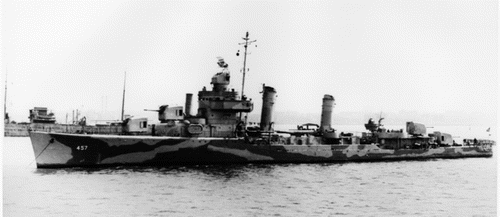
In August 2000, local fishermen in Okinawa found oil floating in the sea in the area north of Motobu Peninsular and reported it to Japan Coast Guard. The wreck of a ship (Fig. 3) was subsequently identified by remote sensing cameras but its name remained unknown. In 2001, diving researchers identified it as belonging to USS Emmons (Ryukyu Shinpo Co. Ltd., Citation2001; Chandler, Citation2005).
Methods
Multibeam echosounder survey
A multibeam echosounder (MBES) survey was conducted using a broadband multibeam echosounder, Sonic 2022 (R2Sonic, LLC), and an accessory system from H. Kan's laboratory (Kan et al., Citation2015; Ono et al., Citation2016). The Sonic 2022 had a variable ultrasonic frequency of 200–400kHz, 256 ultrasonic beams, and a selectable swath of sectors from 10–160°. An ultrasonic frequency of 400kHz was selected for this survey. The typical ultrasonic beam widths parallel and orthogonal to the direction of travel were within one degree of one another at the ultrasonic frequency of 400kHz. To collect backscatter data from the seafloor, Snippet and TruePix options were embedded into the Sonic 2022 system. They act as digital‐sidescan sonars to discriminate bottom material and identify its features. A Position and Orientation System for Marine Vessels (POS/MV) WaveMaster II (Applanix Corp.) combined with a VS111 GPS compass system, with A20 and A30 antennas (Hemisphere Inc.), was used to provide accurate position and orientation (roll, pitch, and heave) data to correct for the effects of vessel motion during survey operations. The sound velocity at sea surface was recorded by a miniSVS sensor (Valeport Ltd) during the MBES survey. We also simultaneously took vertical profiles of sound velocity and water quality using a sound velocity profiler (MicroSVP, AML Oceanographic Ltd) and a logger‐version conductivity temperature depth (CTD) profiler with an optical fast dissolved oxygen (DO) sensor (RINKO–Profiler, JFE Advantech Co., Ltd). HYPACK software was used for the hydrographic survey, and HYPACK and CARIS HIPS & SIPS software were used for data processing. The JGD2000/Japan Plane Rectangular CS XV coordinate system was adopted for Okinawa Island. The Fledermaus (Quality Positioning Services) was used for 3D visualization.
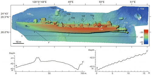
MBES surveys were conducted on August 27, 2014 in a rectangular area spanning 1 × 2km off the north‐east coast of Kouri Island (MBES Area 1 in Fig. 1b) using wide swath sectors ∼120–140°. An overlap of at least ∼20% (typically ∼50%) was implemented throughout the bathymetric survey to ensure 100% coverage of the surveyed area. As complex undulations of reef topography and wreck were known to exist in the surveyed area, we did not use the automatic noise filters provided in HYPACK or CARIS HIPS & SIPS. Instead, we identified noise by determining its geomorphological patterns and continuity, and manually removed it from every beam profile to avoid deleting existing features. The seafloor DEM for this area was created with a grid size of 1m (Fig. 4). The range of depth of Area 1 was 26.6–63.2m.
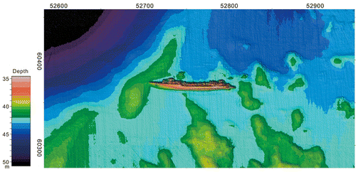
We also conducted an MBES survey in another rectangular area of 400 × 250m (MBES Area 2 in Fig. 1b) to observe the detailed bathymetry around the wreck. We selected narrow swath sectors less than 60° to enhance resolution over small‐scale bottom features because all soundings were concentrated within the swath. To observe the dense dataset, we surveyed the area lengthwise and breadthwise. A detailed DEM of the seafloor with a grid size of 0.2m was created as a base map for the subsequent SfM‐based DEM production. The detailed seafloor DEM over the area of 360 × 185m was improved, as shown in Figure 5, by removing noise with reference to the underwater photos taken for SfM photogrammetry. The depth range of the MBES Area 2 was 34.6–51.7m.
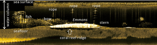
Snippet backscatter data showing the amplitude and reflectivity information of each individual beam were recorded to observe seafloor characterization and classification while surveying the 1 × 2km area. We used the TruePix backscatter data as sidescan waterfall display to record objects in the water column and the seafloor while surveying the 400 × 250m area around the wreck (Fig. 6).
DEM from SfM photogrammetry
In June 2015, scuba‐diving surveys were conducted to document the wreck and survey the geomorphology of the reef around it. It took seven dives to capture images of USS Emmons. For SfM photogrammetry, 1820 images were taken by Kan using a high‐resolution Nikon camera D810 (7360 × 4912 pixels) mounted on Nauticam housing. A frame‐filling fisheye lens (AI AF Fisheye Nikkor, 16 mm, f/2.8D) was used because of the considerable length of the hull, the limited dive time at ∼40m, and to get close to the object under very variable visibility conditions. The images for SfM were taken with natural light and without a strobe light. Fisheye corrections were carried out by Nikon Capture NX–D software for all images and were saved as high‐resolution jpeg files.
Agisoft PhotoScan was used to create the 3D model. The series of 1820 images were imported into PhotoScan and 1716 were used to create the 3D model by deleting low‐quality images as determined by the software. The images were aligned using a high‐quality setting. Following point cloud generation by aligning the images, a dense point cloud was built of the lowest quality with aggressive depth‐filtering parameters to prevent the computer from crashing. Noise was deleted manually: it was carefully divided several times and a mesh was built with the following parameters: arbitrary surface type, sparse cloud source data, low polygon count, and disabled interpolation. The texture of the 3D model was then generated by the build texture operation with generic mapping in mosaic blending mode (Fig. 7a).
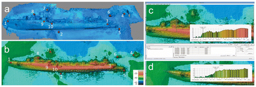
As the original underwater images did not contain GPS location information, we used the preliminary 3D model as a base map to set the ground control points (GCPs) to create a more accurate model by referring to the outcome of the MBES. The outcome of the detailed MBES survey of the 400 × 250m area was used to select the GCPs (Fig. 7b). We first re‐created the DEM (0.1m grid size) using the outcome of the MBES using the WGS84 coordinate system manufactured by QPS Fledermaus. The XYZ (longitude, latitude, and depth) information was then chosen for 10 GCPs using the geo‐picking function of Fledermaus. The accuracy of discriminating objects was higher on the PhotoScan 3D model after texture generation than the MBES 3D model created by XYZ data. Therefore, definite sites/objects on and around the wreck (such as distinct steps in profile or remarkable objects, neighbouring objects of different depths or isolated objects) were carefully selected for GCPs by referring to the plan and profile views of the MBES 3D model using Fledermaus (Fig. 5c–d). All GPCs were set to artificial objects that were easily located in the photographs. The ten GCPs were marked where visible on the 1716 images.
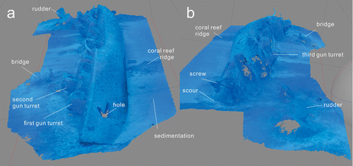
After setting the GCPs, a dense point cloud was built again with the lowest quality and aggressive depth‐filtering parameters. Higher quality procedures were tested to build a dense point cloud, but they were not successful because of the large file size. We observed a satisfactory result for the dense point cloud. Then, we deleted noise from the point cloud. Some noise originated from shoals of fishes around the wreck and some from the bright sea surface reflected in photographs taken from the side. The latter noises appeared as bright areas around objects projecting from the hull. Therefore, we conducted a series of trials to generate a textured 3D model to define these noises in the dense point cloud in order to delete them. Based on the PhotoScan archive file (Fig. 8), the XYZ file was exported as a seafloor DEM with a grid size of 0.0000005 units (degrees), comparable to ∼0.05m. The seafloor model produced by Fledermaus showed the precise shape of the hull and the seafloor over the 120 × 30m area (Fig. 9).
Seafloor geomorphology around the wreck
According to the DEM of the seafloor—at a grid size of 1m—for the north‐east of Kouri Island (spanning 1 × 2km) obtained by our MBES bathymetric survey, a submarine ridge extends east‐north‐east (ENE) from the island (Fig. 4). Numerous spurs and grooves along the ridge are arranged in a NNW–SSE orientation, perpendicular to that of the ridge. Spurs and grooves are the typical geomorphology of a coral reef and consist of elongated narrow ridges and channels that develop along the directions of waves or currents (Kan et al., Citation1997; Duce et al., Citation2016).
Most spurs on the submarine ridge were 30–60m wide. The difference in height between the spurs and the grooves was approximately 5–10m. The spurs had lower undulations at heights of 2–3m at depths greater than 35m. The uniform orientation of the spurs and grooves did not persist below 40m; these depths were instead characterized by reef mounds without long axes, with diameters ranging 15–40m and heights 2–3m. These small reef mounds seldom occurred abundantly below a depth of 42m, where offshore ridges are oriented obliquely with respect to the spurs and grooves. Beyond 42m, gentle slopes formed due to carbonate sediments with slope angles of five degrees between 42 and 52m of depth, and one degree below 52m of depth.
USS Emmons lay along the edge of the coral reef features (Fig. 4). Its bow was located beside an offshore ridge extending ∼2m in height NE–SW. The stern was located beside a reef slope spur extending NNW–SSE. The ship lay between these points, close to the end of the reef‐slope grooves.
Present condition of USS Emmons
The data acquired during this project resulted in high‐resolution plans enabling site assessment and serve as a baseline for future studies. Emmons lay portside up 42–43m deep on the seafloor, oriented in an approximately east–west direction. From the fact that the depth of the seafloor was 42m at the centre of the hull, where the beam was widest, and that the shallowest part of the hull was at a depth of 34m, we estimated that the highest part of the shipwreck protrudes 8m above the seabed, and that approximately 3m of the ship's 11m beam was buried in the seabed or had been vertically compressed.
Emmons was found resting on a coral reef ridge below its forward third (Fig. 9, profile x–x’). The ridge lies north–south, oriented perpendicular to the hull, 1–2m high. Consequently, the hull was bent slightly to the starboard abaft the bridge. The bending of the hull at the coral reef ridge was also observed in the sidescan image Figure 6.
A strong tidal current was dominant around Emmons with directions either from west to east or east to west. The bow‐to‐stern axis of the hull (west to east) matches the direction of the tidal current. This might have contributed to the high stability of the hull. In addition to the direction of the hull, Emmons lay at the lower end of a fore‐reef slope at the flat‐bottomed depression between the lower‐reef slope and the offshore ridge (Fig. 4). Whereas the outer slope of the offshore ridge was ∼6 degrees, there was a gentle slope angle of ∼1 degree between the top of the reef and its lower slope, where the vessel lay. The height of the offshore ridge was only 1–2m, but it acted as a retaining wall for reef sediment moving down from the upper slope. Emmons might also have maintained its location because the offshore ridge prevented it from sliding down to the deeper fore‐reef slope.
The hull of the destroyer had listed as its bottom had turned toward the upper‐reef slope, where the accumulation of sediment was observed on the bottom (south) of the ship. This was owing to reef sediment from the upper‐reef to the lower‐reef slope due to gravity (mass movement of sediment). The ship's hull dammed the sediment along the slope of the reef, which moved offshore, downward from it. Sand ripples at a wavelength of 1.5m and a height of 0.1m were observed beside the bow of the ship (Fig. 9, profile y–y’). The orientation of the ripples coincided with the predominant east–west tidal current. On the other hand, a scour ∼6m long and 1–4m wide was observed at its stern, excavating the seafloor to a depth of ∼0.8m.
We did not observe sediment covering the hull and the deck (south) of the wreck. It showed that the rate of in situ sediment accumulation was extremely slow at a depth of ∼40m on the coral reef slope. Moreover, the fore‐reefs of Ryukyu Islands are very susceptible to massive wave action associated with typhoons (Kan, Citation1995; Kan, Citation2011): however, Emmons seemed not to have experienced damage from major natural events since its sinking in 1945.
The photographs indicated that damage to the ship's hull at the stern and the bridge was considerable. The bridge and the main mast were crushed on the starboard side, and were scattered 6–10m from the hull (Figs 9, 10a–b). The stern had mostly collapsed from its screw bearings (Fig. 10c): a 5.5 × 5.5m part was found overturned approximately 16m north‐east of the starboard side of the hull (Fig. 10d). The rudder (∼3 × 0.5m) was intact on the overturned portion of the wreck in a NNW–SSE orientation, nearly perpendicular to the hull.
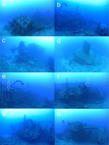
A hole 3 × 2m was observed at the top of the port side of the ship's hold (Figs 8a, 9) between the bow and the first gun turret. Both the first and the second funnels, which had been on top of the quarters for the central crew, had fallen away (Fig. 10e–f), as had the stern mast that had been installed atop the quarters. The first and second gun turrets (5‐inch artillery) were in good condition, with the first facing to port (Fig. 10g) and the second facing forward (Fig. 10h). The 20mm autocannon on the port side of the bridge was in good condition. The mounting for the 40mm autocannon on the port side of the quarters of the stern crew was intact, as was the third gun turret located behind it facing starboard. The fourth gun turret had been lost along with the base of the hull. The remaining gun turrets and autocannons of Emmons were found all pointing at the same angle as the deck. This coincides with evidence that the attack occurred as the planes flew barely above sea level.
To summarize, the hull of Emmons lay on a coral reef ridge and was bent slightly. Since it sank it has not moved much. The orientation of the hull aligns with the direction of the tidal current. This might have contributed to the high stability of the hull in its present position. In addition, an offshore ridge acting as a retaining wall prevented it from sliding down to the deeper fore‐reef slope.
Toward future preservation
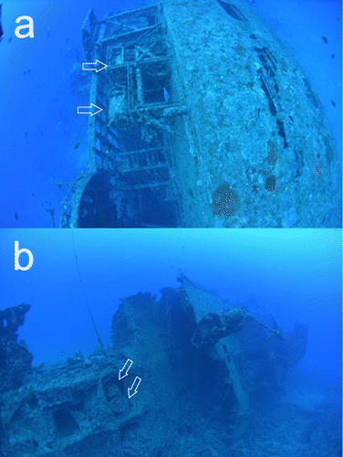
Examination of the photographs suggests that at least four Mark IX depth charges remained. Two were located between the 40mm autocannon mount and the third gun turret at the rear port (Fig. 11a), and two were in the damaged part of the stern (Fig. 11b). We reported the remains of these unexploded bombs to the Japan Coast Guard in January 2017, who decided to set warning buoys over the site (Japan Coast Guard, Citation2017). Discussions regarding the treatment of these unexploded bombs has started only recently (The Okinawa Times, Citation2018). There are concerns over the rights of ownership of the hull or the possible damage to the hull if the bombs were detonated in a controlled manner, and thus, the local government is searching for a solution to resolve the dilemma of safety and preservation. This problem seems to be a major concern for the formulation of policies for preservation of WWII sites, not only in the case of Emmons, but also other WWII underwater sites.
The rate of sedimentation on the slope of the reef was estimated to be extremely low compared to that of a coral reef lagoon (such as the Chuuk Atoll lagoon) or a tropical bay (such as Pearl Harbor). Therefore, the collapsed parts of the deck and stern have avoided massive sedimentation. This has contributed to keeping the deck exposed, making our observations possible even after it lay on the seabed for more than 70 years. Future verification, by comparing regularly repeated 3D SfM models, may reveal spatial changes in the wreck (see CitationMertes et al., 2017).
While the WWII wrecks recorded in Chuuk Lagoon, Micronesia (MacLeod, Citation2016) might be expected to have a lower flux of dissolved oxygen on corroding interfaces, Emmons is subject to a strong tidal current that normally involves an increase in water movement and oxygen flux. According to the vertical dissolved oxygen (DO) profiles off the Emmons’ wreckage (Fig. 12a), DO saturation levels exceeded 89% in the water column and were greater than 94% at the depth of the wreck site (40m). No oxygen deficiency was observed around the wreck affecting marine organisms, such as reported in Miller et al. (Citation2002). Although some stratification of DO was found at 28m, 53m, and 68m at the bottom at 10:54 on August 27, 2014, the stratified water column receded at 15:54. As it is unlikely that vertical mixing at this site due to tidal and/or wind mixing caused this homogenization within the short period of five hours from 10:54 to 15:54, but rather the strong tidal current exchange stratified a water column of 70m with the homogeneous water originating from the outer sea.
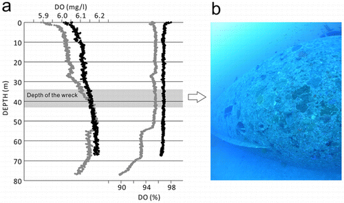
The hull of the wreckage was covered by encrusting corals and coralline algae (Fig. 12b), which are common biota in deep fore‐reef environments in Ryukyu Islands (Sagawa et al., Citation2002). The corrosion rate of steel shipwrecks is also thought to decrease with biofouling (Johnson et al., Citation2006a; Johnson et al., Citation2006b). Many cracks were also observed on the hull of the Emmons during our scuba survey, raising concerns about some deterioration of the metal. The data obtained in this study will contribute to the detailed monitoring of the wreck in the future, as seen in studies of USS Arizona (Foecke et al., Citation2010), for future preservation assessment.
USS Emmons as WWII UCH
The UCH management of USS Arizona, in Hawaii, can provide insights for the future management of USS Emmons. USS Arizona is a symbolic American battleship sunk by the Japanese on 7 December 1941 in Pearl Harbor. After burning for two days, USS Arizona eventually sank. A total of 1177 died on the day out of a crew of 1511, with 334 survivors. The ship is still on the seafloor and was designated an underwater cultural heritage site in 1989. The Arizona Memorial for war victims was constructed at the site as well as an information centre at the port to inform people of the history of the war and convey messages of peace. The area in Hawaii was turned into a WWII memorial park, and one of nine World War II Valor in the Pacific National Monuments (Slackman, Citation2012: 64).
USS Arizona has four major roles: 1) it is an underwater cultural heritage site that has been extensively researched, and continuously monitored and protected by the National Park Service; 2) it greatly contributes to disseminating the history of the war and messages for peace through exhibitions at the information centres including the testimonies of survivors; 3) as a historic park managed by the National Park Service, it is now one of the major visitor destinations with more than 1.8 million visitors a year (http://pearlharbor75thanniversary.com/); 4) it is a memorial for war victims, and a memorial service occurs on particular days every year.
Moreover, USS Arizona serves to remind the public and the ship's surviving crew of the war. From this perspective, it is primarily a memorial and a grave. The surviving crewmembers of Arizona have the choice of being interred together with the ship and their deceased crewmembers after a funeral at the Arizona Memorial. The urns of these veterans are placed in a well at Barbette no. 4. Forty‐one of the 334 survivors have chosen to do so thus far (US National Park Service, Citation2017).
In the case of USS Arizona, preservation in situ seems to be greatly valued. The hull has been neither recovered nor exhibited on land following scientific conservation, but rather remains preserved under water at Pearl Harbor where it was sunk. An association has been organized for the survivors and the bereaved of USS Arizona's crew to meet regularly and commemorate the incident. It is clear that the ship is not going to be removed from its present location, evident in the fact that the memorial monument has been constructed over its sunken hull.
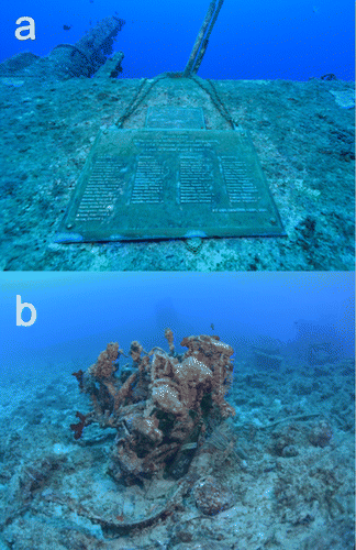
USS Arizona, having been preserved in situ and used hence, provides some indication to assess USS Emmons as an underwater cultural and war heritage site. The case of USS Emmons is similar in several respects, for example a memorial plate for the war victims has been attached to the ship (Fig. 13a). On June 23, Okinawa Memorial Day (the day General Ushijima committed suicide is regarded as the end of the Battle of Okinawa), USS Emmons was featured in the media in commemoration (Asahi Newspaper Company, Citation2011). Since then, local divers have led the memorial rituals. An association has also been organized for the survivors and the bereaved of the crew of the USS Emmons to meet regularly and commemorate the incident (https://www.ussemmons.org/).
USS Emmons is a war heritage site in Japan testifying to historic events: the Battle of Okinawa, a ground battle that led to a loss of 200,000 lives, and the kamikaze attack. It has been more than 70 years since the war ended, and the number of living survivors who experienced it is gradually decreasing. The documentation of the war through material evidence, such as research on USS Emmons, can supplement survivor accounts to be passed down for posterity.
War ruins tell a detailed story, not only from the available physical evidence, but also by calling attention to the people involved and the lives of their bereaved. The tragedy of Emmons can be recounted from many perspectives (Billingsley, Citation2005). There is still an engine on the seafloor thought to be from a Japanese Army kamikaze plane (Fig. 13b), off the damaged stern of the ship. Survivors from kamikaze planes reported that many young men, including university students, left on suicide missions with painful hesitation (Asahi Newspaper Company, Citation2001: 134; Nagasawa, Citation2008; Nagasawa, Citation2013: 46). USS Emmons and kamikaze were both mythologized as instances of valour in war by partisans, but both were victims.
The battlefields in Okinawa had been inhabited by civilians at the time of WWII, and a large number of people suffered during it and in its aftermath. Material evidence of the war, such as the wreck of USS Emmons, serve as vivid reminders, and thus have significant cultural and historical value.
Conclusion
Creating accurate maps and visualizing underwater sites is important for the future preservation, long‐term study, and use of underwater archaeological sites. The underwater site chosen in this research was the WWII wreck of USS Emmons, a 106m‐long battleship that sank 40 deep north‐east of the coast of Okinawa Island in Japan. USS Emmons took part in the Battle of Okinawa in March 1945, and was attacked by five kamikaze aircraft on April 6. It is the only battleship that was sank by kamikaze attacks. It remained undiscovered on the seafloor for 45 years after the war.
In this study, we generated two kinds of high‐resolution bathymetric maps. One had a 1 × 2km rectangular area with a grid size of 1m using multibeam echosounder (MBES) survey to observe geomorphological, sedimentological, and oceanographic conditions around the site. The other was a 120 × 30m map with a grid size of ∼0.05m for the site and its remains. To generate the latter, ultra‐high‐resolution bathymetric map, we developed a novel method combining SfM photogrammetry with high‐resolution MBES surveys, where ground control points (GCPs) were established to create a more accurate model by referring to the outcome of the MBES. Consequently, we successfully obtained an underwater 3D SfM model constructed on geographical coordinate systems. This combination of technologies allowed us to create a seafloor DEM at considerably higher resolution than that generated by multibeam bathymetry. Moreover, the 3D SfM model recorded detailed surface conditions, such as cracks and other damage, and adhering objects and organisms. It is therefore expected that this method can be used to create 3D models superior to those generated by multibeam bathymetric DEM, providing baseline data for the long‐term study and conservation of underwater sites.
Seafloor bathymetry around the site and the 3D model of the ship generated in this study provide the primary record of the current state of the wreck and allow for the investigation of the site formation process, and the establishment of various measures for its future preservation and monitoring. The hull of Emmons lies port side up on a coral reef ridge below its forward one‐third and bent slightly to the starboard abaft the bridge. The axis of the hull (west to east) aligns with the tidal current. This might have contributed to its high stability. Furthermore, an offshore ridge acted as a retaining wall and prevented it from sliding down to the deeper fore‐reef slope. Thus, it has maintained its position since it sank. The accumulation of sediment with sand ripples was observed below (south) of the ship, and a scour was observed at its stern. By referring to the historical descriptions of the sinking, the remains scattered around its hull also seemed to have maintained their positions when it sank.
The 3D data obtained using the above process makes it possible to share the site information of war ruins (shipwrecks) that are difficult to physically move or recover or should remain in situ as war graves. This study may serve as an important case to consider in the context of the preservation of other underwater WWII battle sites, which will become cultural heritage sites by 2045 under the 2001 Convention on the Protection of the Underwater Cultural Heritage.
Acknowledgements
This study was supported by JSPS KAKENHI (S) Grant Number JP16H06309 and (A) Grant Number JP25242026. We thank Ken Toguchi (University of Ryukyus), Yosuke Nakashima (Ariake National College of Technology), Satoshi Okumura, Kouichi Nakano (Tokyo Co. Ltd.), and Captain Shigeki Nakamura for help with the bathymetric survey, Masami Sannoh (Nihon Mikuniya Corporation) for MBES data processing, Kyoko Honda for the scuba‐diving survey, Paul A. Cogan (The US National Archives and Records Administration) for providing historical records, Lisa Crunk (Naval History & Heritage Command) for a picture of USS Emmons. We appreciate Miranda Richardson and two anonymous reviewers who improved our manuscript. We also thank Editage (http://www.editage.jp) for English language editing.
Additional information
Funding
Related Research Data
References
- Asahi Newspaper Company, 2001, Sora‐no Kanata‐ni (Reminiscences of Tome Torihama), 134. Fukuoka: Ashi Publisher.
- Asahi Newspaper Company, 2011, Sea of reunion (Saikai no Umi) USS Emmons sleeping in Okinawa 1–4. The Asahi Shinbun (newspaper), 6–9 June 2011 evening edition, 2.
- Balletti, C., Guerra, F., Scocca, V. and Gottardi, C., 2015, 3D‐integrated methodologies for the documentation and the virtual reconstruction of an archaeological site, The International Archives of the Photogrammetry. Remote Sensing and Spatial Information Sciences XL–5/W4, 215–222.
- Billingsley, E. B. (ed.), 2005, The Emmons Saga: A History of the USS Emmons (DD457–DMS22). New York: iUnivers.
- Chandler, J. W., 2005, Rediscovery of the USS Emmons, in E.B. Billingsley (ed.), The Emmons Saga: A History of the USS Emmons (DD457–DMS22), 438. New York: iUniverse.
- De Reu, J., Plets, G., Verhoeven, G., De Smedt, P., Bats, M., Cherretté, B., De Maeyer, W., Deconynck, J., Herremans, D., Laloo, P., Van Meirvenne, M. and De Clercq, W., 2013, Towards a three‐dimensional cost‐effective registration of the archaeological heritage. Journal of Archaeological Science 40, 1108–1121.
- Duce, S., Vila‐concejo, A., Hamylton, S.M., Webster, J.M., Bruce, E. and Beaman, R.J., 2016, A morphometric assessment and classification of coral reef spur and groove morphology. Geomorphology 265, 68–83.
- Ducke, B., Score, D. and Reeves, J., 2011, Multiview 3D reconstruction of the archaeological site at Weymouth from image series. Computer & Graphics 35, 375–382.
- Foecke, T., Ma, L., Russell, M.A., Collin, D.L. and Murphy, L.E., 2010, Investigating archaeological site formation processes on the battleship USS Arizona using finite element analysis. Journal of Archaeological Science 37, 1090–1101.
- Griffin, J.J. Jr., 1945, Action report and sinking of USS Emmons (DMS22), 6 April 1945. Office of Naval Records and Library 18.
- Guidi, G., Russo, M. and Angheleddu, D., 2014, 3D survey and virtual reconstruction of archeological sites. Digital Applications in Archaeological and Cultural Heritages 1, 55–69.
- Henderson, J., 2013, Mapping submerged archaeological sites using stereo‐vision photogrammetry. IJNA 42.2, 243–256.
- Kan, H., 1995, Typhoon effects on sediment movement on reef edges and reef slopes, in O. Bellwood, H. Choat and N. Saxena (eds), Recent Advances in Marine Science and Technology ’94, 191–201. Townsville: Pacon International and James Cook University.
- Kan, H., 2011, Ryukyu Islands, in D. Hopley (ed.), Encyclopedia of modern coral reefs: Structure, form and process, 940–945. Springer: Encyclopedia of Earth Science Series.
- Kan, H., Hori, H. and Ichikawa, K., 1997, Formation of a coral reef‐front spur. Coral Reefs 16, 3–4.
- Kan, H., Urata, K., Nagao, M., Hori, N., Fujita, K., Yokoyama, Y., Nakashima, Y., Ohashi, T., Goto, K. and Suzuki, A., 2015, Submerged karst landforms observed by multibeam bathymetric survey in Nagura Bay, Ishigaki Island, southwestern Japan. Geomorphology 229, 112–124.
- Japan Coast Guard, 2017, Notices to Mariners and Navigational Warnings, No. 17–181, http://www1.kaiho.mlit.go.jp/TUHO/vpage/visualpage_en.html, last updated 31 October 2017, (accessed 31 October 2017).
- Jeffery, B., 2004, World War II underwater cultural heritage sites in Truk Lagoon: Considering a case for world heritage listing. IJNA 33.1, 106–121.
- Jeffery, B., 2012, The future of Chuuk Lagoon's submerged WWII sites. Bulletin of the Australasian Institute for Maritime Archaeology 36, 15–30.
- Jeffery, W.F., 2007, War graves, munition dumps and pleasure grounds: A post‐colonial perspective of Chuuk Lagoon's submerged WW II sites. Doctoral dissertation, James Cook University, Townsville, http://eprints.jcu.edu.au/2068, last updated 19 January 2009 (accessed 17 August 2017).
- Johnson, D.L., Wilson, B.M., Carr, J.D., Russell, M.A., Murphy, L.E. and Conlin, D.L., 2006a, Corrosion of steel shipwreck in the marine environment: USS Arizona–Part 1. Materials Performance 45.10, 40–44.
- Johnson, D.L., Wilson, B.M., Carr, J.D., Russell, M.A., Murphy, L.E. and Conlin, D.L., 2006b, Corrosion of steel shipwreck in the marine environment: USS Arizona–Part 2. Materials Performance 45.11, 54–57.
- Lenihan, D.J., Delgado, J.P., Dickinson, B., Cummins, G., Henderson, S., Martinez, D.A. and Murphy, L.E., 1989, Submerged cultural resources study: USS Arizona Memorial and Pearl Harbor National Historic Landmark. Southwest Cultural Resources Center Professional Papers 23, 192. Santa Fe, New Mexico.
- Liritzis, I., Al‐otaibi, F.M., Volonakis, P. and Drivaliari, A., 2015, Digital technologies and trends in cultural heritage. Mediterranean Archaeology and Archaeometry 15, 313–332.
- Macleod, I.D., 2016, In‐situ corrosion measurements of WWII shipwrecks in Chuuk Lagoon, quantification of decay mechanisms and rates of deterioration. Frontiers in Marine Science 3, Article 38, 1–10.
- Mertes, J., Thomsen, T. and Gulley, J., 2014, Evaluation of structure‐from‐motion software to create 3D models of late nineteenth century Great Lakes’ shipwrecks using archived diver‐acquired video surveys. Journal of Maritime Archaeology 9, 173–189.
- Mertes, J.R., Zant, C.N., Gulley, J.D. and Thomsen, T.L., 2017, Rapid, quantitative assessment of submerged cultural resource degradation using repeat video surveys and Structure from Motion. Journal of Maritime Archaeology 12, 91–107.
- Miller, D.C., Poucher, S.L. and Coiro, L., 2002, Determination of lethal dissolved oxygen levels for selected marine and estuarine fishes, crustaceans, and a bivalve. Marine Biology 140, 287–296.
- Monfils, R., Gilbert, T. and Nawadra, S., 2006, Sunken WWII shipwrecks of the Pacific and East Asia: The need for regional collaboration to address the potential marine pollution threat. Ocean and Coastal Management 49, 779–788.
- Mooney, J.L., 1963, Dictionary of American Naval Fighting Ships, Vol.II. Washington: Navy Dept., Office of the Chief of Naval Operations, Naval History Division. (https://www.hazegray.org/danfs/destroy/dd457txt.htm)
- Nagasawa, F., 2008, Akatsuki‐no Zuiun: A Letter Arrived over Time. Tokyo: Bungeisha Publisher.
- Nagasawa, F., 2013, Jiyu‐no Tsubasa‐wo Motomete (Looking for wings of freedom): A future story of Akatsuki‐no Zuiun. Self‐published.
- Nornes, S.M., Ludvigsen, M., Ødegård, Ø. and Sørensen, A.J., 2015, Underwater photogrammetric mapping of an intact standing steel wreck with ROV. IFAC Papers OnLine 48.2, 206–211.
- Ono, R., Katagiri, C., Kan, H., Nagao, M., Nakanishi, Y., Yamamoto, Y., Takemura, F. and Sakagami, N., 2016, Discovery of iron grapnel anchors in early modern Ryukyu and management of underwater cultural heritages in Okinawa, Japan. IJNA 45, 75–91.
- Ryukyu Shinpo Co. Ltd., 2001, The wreck of US Navy off Kouri Island. The Ryukyu Shinpo (newspaper), 18 March 2001 morning edition, 24.
- Sagawa, N., Nakamori, T. and Iryu, Y., 2002, Pleistocene reef development in the southwest Ryukyu Islands, Japan. Palaeogeography, Palaeoclimatology, Palaeoecology 175, 303–323.
- Slackman, M., 2012 (10th edn), Remembering Pearl Harbor–The Story of the USS Arizona Memorial. Honolulu: Pacific Historic Parks.
- Stone, S.C.S., 2003 (4th edn), Pearl Harbor: The Way It Was–December 7, 1941. Island Heritage Publishing.
- The Okinawa Times, 2018, Underwater unexploded bombs: searching for processing method. Okinawa Times (newspaper), 27 February 2018 morning edition, 37.
- UNESCO, 2002, Convention on the Protection of the Underwater Cultural Heritage. Records of the General Conference, 31st Session, Paris, 15 October to 3 November 2001, Vol. 1 Resolutions, 50–61.
- US National Park Service, 2017, USS Arizona Interments, https://www.nps.gov/valr/learn/historyculture/ussarizonainterments.htm, last updated 29 March 2017 (accessed 19 August 2017).
- Verhoeven, G., Taelman, D. and Vermeulen, F., 2012, Computer vision‐based orthophoto mapping of complex archeological sites: The ancient quarry of Pitaranha (Portugal–Spain). Archaeometry 54, 1114–1129.
- Wilde, E.A. Jr., 2001, The U.S.S. Emmons (DD–457/DMS–22) in World War II: Document and Photographs (Revised Edition). Needham, Massachusetts.
- Yamafune, K., Torres, R. and Castro, F., 2016, Multi‐image photogrammetry to record and reconstruct underwater shipwreck sites. Journal of Archaeological Method and Theory 24.3, 703–725.