Abstract
Previously the author described how control engineering can be introduced using little mathematics in a first year course, the aim being to make the subject accessible across different degrees. One reaction to this was that it was a good idea, but there was not space to include it in the curriculum where, typically control engineering is not introduced until the second year. This paper describes how the author has used a review of the first year teaching to develop a module in which feedback, control and electronics are integrated coherently. This is beneficial as concepts in control and electronics mutually reinforce each other. This has been achieved during a reduction in the available time for teaching the material. This paper describes the strategy used to successfully develop the module, the integrated module and positive student reaction.
Introduction
A recent survey on the teaching of control theory in the UK (CitationRossiter et al. 2008) noted the commonality of what is taught. Most universities who responded started the teaching of control in the second year of the undergraduate course, with basic material such as calculus, signals, and Laplace having been covered in the first year.
Although control is core to degrees such as Control Engineering, Cybernetics and Robotics, for many other engineering disciplines it is treated as an ‘auxiliary’ course and students can be less motivated to study it. This is regrettable as feedback and control are interdisciplinary.
Another issue is that control can be treated too mathematically, which again can be demotivating. The author listened to a talk recently where the speaker described control as mathematics! Ron CitationLeigh (1992) appreciated this issue: the first three chapters of his book do not include mathematics. His book is a ‘companion and friend’ for students struggling to understand basic concepts ‘despite the multiplicity of available control books at all levels’.
As such, it is the author’s contention that control should be introduced in the first year, in a variety of engineering disciplines, in an accessible manner. When the author showed how control can be introduced ‘using little mathematics’ at UKACC Control 2010 (CitationMitchell 2010), there were positive comments about the approach, tempered with the problem that there was no room to incorporate such an approach in the first year.
During 2010, in Systems Engineering at the University of Reading, a review of Part 1 took place meaning fewer lectures were available for feedback, control and electronics. The result of this is the ‘Cybernetics and Circuits’ module in which these topics are integrated in a coherent manner.
In the module, feedback is still introduced with ‘little mathematics’, and it is shown how the concept can be applied in different disciplines. In addition, topics introduced in electronics are readily applied to other feedback systems, and operational amplifiers are described which are used in feedback configurations.
The association of feedback systems with electronics and other applications means that the students are shown that the analysis is applicable to ‘real systems’. This is one key way in which students are engaged (CitationWilliams & Williams 2011).
Overall the module provides a good introduction to both feedback and electronics, demonstrating that both fit together. This should help in future years to combat the compartmentalisation of the topics, demonstrating for instance that control is an integral part of electronic engineering.
In this paper, the strategies used to reorganise and reduce the relevant material are described, and an introduction is given to the Cybernetics and Circuits module and how it fits into the undergraduate degrees in Systems Engineering at Reading. It is then demonstrated how feedback and control can be introduced in the first year. Finally some observations are made on the approach, based on comments from students.
Reorganising the first year modules at Reading
In the School of Systems Engineering at Reading, students can study Electronic Engineering, Cybernetics, Robotics, Artificial Intelligence, Computer Science or Information Technology. Students take six modules, some being compulsory for each degree. Students are recommended to choose any optional modules such that they take the compulsory modules for more than one degree. In Part 2 they can select any degree for which they have taken the compulsory modules.
In 2010 a review of these degrees and associated modules was instigated. Prior to this review, there were 20 lectures in Part 1 on feedback and control in one module, and 20 lectures on circuit theory, 10 on operational amplifiers and 10 on semi-conductors in another module. A consequence of the reorganisation is that there was only space for 40 lectures for this type of material in Part 1 in a module entitled Cybernetics and Circuits. The semi-conductors lectures were deemed too advanced for Part 1, and so were incorporated in a module in Part 2.
The module is compulsory for students studying Electronic Engineering, Cybernetics, Robotics and Artificial Intelligence. They also take a Mathematics module, covering calculus, differential equations, complex numbers and matrices; the Computer Applications module which introduces digital electronics, computer networking, robotics and artificial intelligence; as well as modules on Programming and Software Engineering. Computer Science students can choose to take the Mathematics and Cybernetics and Circuits modules, so the module needed to be accessible to such students provided they had a suitable background in mathematics and physics.
The key to reducing 50 lectures to 40 was appreciating that the topics were interrelated and so could be covered in one topic and built on another. So for instance, complex numbers are clearly needed in studying alternating current (a.c.) circuits. It is then possible to show how such circuits can be represented in the block diagram format used in control systems. Thence it is logical to demonstrate how to determine the frequency response of a motor controlled using feedback.
It was decided that the 20 lectures on circuits could be reduced to 15, but in so doing there was not time to cover asymptotic approximations in the a.c. circuits lectures. However, it was possible to move that topic into the feedback lectures.
Some students have difficulty relating to the Laplace operator: the revised module helps here. Students are first introduced to the use of jω for differentiation of sinusoids. Here ω has a real interpretation, namely angular frequency. It is then a logical step to introduce s for the analysis of non-sinusoidal signals.
Although the revisions concerned the Cybernetics and Circuits module, it was also sensible to consider the interaction with the mathematics module the students take. Previously a.c. circuits were taught in the spring term, building on complex numbers taught in Maths in the late autumn term. However, step response of feedback systems were introduced in the autumn term, but the associated material on differential equations was given in the spring term.
In the revised module, a.c. circuits are taught at the end of the autumn term, just after complex numbers are taught, helping to mutually reinforce the material. Time domain response of feedback systems is now taught midway through the second term, just after differential equations are covered in mathematics. In fact, the same numerical examples are analysed using the Laplace operator in Cybernetics and Circuits and differential equations in Mathematics.
In the first term the module comprises five lectures on feedback systems, introducing the key concepts ‘with little mathematics’ as before, and 15 lectures on circuit theory. In the spring term, there are 10 lectures on feedback, building on the first term, and another 10 on operational amplifiers.
It has thus been possible to reorganise the material to produce a module which is coherent, and links well with the associated mathematics module. The next section gives more details of the module. After that, the feedback material is described in greater detail.
The cybernetics and circuits module
The module comprises 40 lectures with associated practicals. Between lectures there is an online test to do on the virtual learning environment (VLE), Blackboard, which students can use to determine if they understand the material. There are also tests on Blackboard to help prepare for the practicals (CitationMitchell 2012).
In the circuits course in the autumn term, direct current (d.c.) circuits are introduced and analysed using techniques such as the potential divider, principle of superposition, Kirchhoff’s laws and Thevenin’s theorem. For a.c. circuits, complex impedances are introduced, circuits analysed, filters described and frequency response graphs plotted.
The feedback lectures begin by demonstrating the applicability of feedback to many different systems. Block diagram representation and modelling is performed, where transfer functions are assumed to be constant. The consequences of limits in feedback systems are discussed.
In the spring term electronic circuits are represented as feedback systems and sinusoidal analysis performed, with the output being determined from the system transfer function. This analysis is then applied to other systems such as motors. Bode and polar plots of frequency response are given, including asymptotic plots which were moved from the a.c. circuits lectures.
The exponential response to a step input is argued intuitively for a first-order feedback system. The Laplace operator is introduced, as an extension of jω, and it is shown how the step response can be determined from the associated transfer function. The systems are then simulated using MATLAB. Second-order systems are introduced, simulated, and examples are given of under- and over-damped systems. It is then shown how these responses can also be found simply from the transfer function. The concept of damping ratio is introduced and related to the Q factor used in filters.
In the operational amplifier course, the basic components are described and various configurations shown, including active versions of filters described in a.c. circuits. Block diagram representation of these systems is used for their analysis.
A custom book covering both the Cybernetics and Circuits and Computer Applications modules was developed (CitationMitchell et al. 2011). It contains material from books on Circuit Theory, Operational Amplifiers, Logic, Robotics and Artificial Intelligence, as well as special chapters written by the author for the feedback lectures.
The next section covers the control content of the module in more detail, and how it relates to and benefits the rest of the module.
The feedback course
The feedback course comprises 15 lectures. About half way through most lectures, there is a question which the students are expected to attempt in the lecture theatre. This helps address attention span issues (CitationBunce et al. 2010) by providing a break from the slides and an opportunity for the students to engage with the material by attempting the question, asking for help if they need it.
Introductory lectures
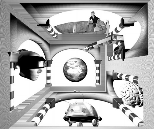
The initial lectures on feedback are aimed at setting the scene, consistent with CitationWiener’s (1948) definition of cybernetics: control and communication in the animal and the machine. The image in , inspired by one of MC Escher’s wood carvings, is used to illustrate applications of feedback. Control is depicted by a steersman (from whence comes the word cybernetics) and a robot manipulator. Artificial intelligence, which is relevant as learning is a feedback process, is depicted by a brain and a mobile robot, which is used for research into learning (CitationMitchell et al. 2010). Virtual reality is depicted, where humans and computers communicate in a feedback loop. The Earth illustrates the Gaia theory which in effect says that life and Earth act in feedback loops. Feedback is thus applicable to many different systems. This introduces the material in the module and relates it to the robotics and artificial intelligence topics in Computer Applications.
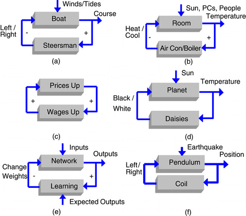
The images in are then used to illustrate systems where two components interact in a feedback loop, often for control.
The first example used, , depicts a steersman ensuring the boat follows a given course despite winds and tides. The + and – reflect the fact that if the boat steers to the right, says, the control action is to steer in the opposite direction: the net sign round the loop is negative, and hence there is control.
It is then shown that the same structure applies to a driver of a car, both in terms of following the road or the correct speed, a robot arm positioning its gripper at the right place, the temperature control of a room, , or the human body.
These systems are contrasted with the simple wage-price economic system in . Here, for instance, if prices rise, higher wages are demanded which if granted increase the costs and so prices rise. Here the net sign round the loop is positive, representing a problematic inflationary spiral.
It is then explained that such ‘positive feedback’ can be advantageous, allowing a system to adjust rapidly, if there is also ‘negative feedback’. This is illustrated by Daisyworld (CitationWatson & Lovelock 1983), in which black or white daisies grow to affect the planet temperature, as shown in . When the planet first becomes warm enough for daisies to grow, black daisies grow absorbing heat, thereby encouraging more black daisies. Rapidly the planet’s temperature rises to the optimum: here the net sign round the loop is positive. Thereafter, the net sign around the loop is negative, with black and white daisies growing in different proportions, heating or cooling as appropriate, thereby controlling the planet temperature.
That feedback applies to learning is illustrated using a neural network adapting the values of its weights. Inputs are provided and the outputs calculated. These outputs are compared with what they should be, and any difference is used to adjust the weights. This is shown in .
Finally, a feedback seismometer is illustrated (CitationUsher et al. 1977). Here a pendulum, encased in a coil, is moved when there is an earthquake, as shown in . Such movements are countered by a force generated by passing a current through the coil. In effect this is a system seeking to control the pendulum’s position. However, the system output is not the controlled pendulum position, but the current in the coil which is proportional to the force generated by the coil, which equals that of the earthquake.
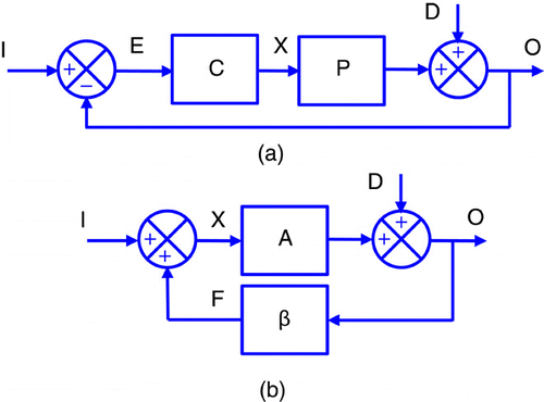
The block diagram in is then introduced and it is shown that this can represent many of the control systems previously described. It is demonstrated that similar block diagrams can represent analogous systems, such as two tanks connected by a pipe, an electronic circuit with a resistor and a capacitor, and a simple motor. In all cases here, the aim is to illustrate principles of feedback and to show that they apply in many types of system.
Block diagram analysis
The next stage is to consider the development of models of systems by dividing them into sub-systems and then combining these together. The basic elements are ‘blocks’ and summing junctions, between which signals of different type pass. The concept of a transfer function is introduced, where here it is a scalar quantity with no dynamics. It is stated that ultimately the transfer function of the whole system is to be determined, by combining those of the sub-systems. This analysis is done on the two configurations shown in .
clearly can be used to represent a control system, where the aim is that the output O equals the input I despite disturbance D. That in is more general and can be used where the aim is for O to be a multiple of I: an electronic amplifier for instance.
The systems in this introductory course have one main loop and sometimes an inner loop as well. Their overall transfer function can be found in terms of ‘forward’ and ‘loop’ transfer functions. ‘Forward’ is that between input and output ignoring other signals coming in: for it is C * P. ‘Loop’ is that when going round a complete loop, ignoring signals entering the loop: for it is –C * P. The overall transfer function is ‘forward over one minus loop’ (or minus both loops where there is an inner loop).
The response of the system is found by relating input I to output O assuming that D is zero, finding how D relates to O assuming I is zero, and combining the two, using the Principle of Superposition (a concept already introduced in the circuits lectures). So for , the relationships between I, D and O are found as follows:
For the system in , the same form of analysis shows that
It is assumed that the component values are constant, and values of O found using the above. The importance is demonstrated of the loop transfer function being large. Then for instance, CP/(1 + CP) is approximately one and 1/(1 + CP) is approximately zero, and hence O equals I, is unaffected by D or by changes in P. For the second system, O equals −I/β, is unaffected by D or by changes in A.
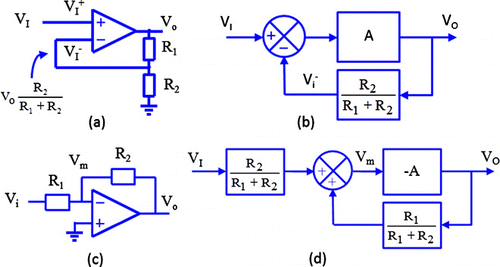
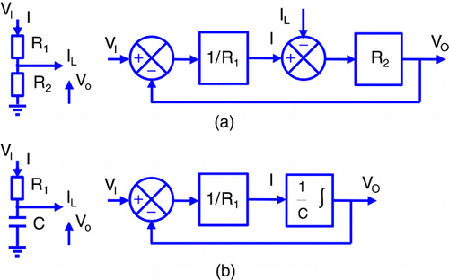
The practicality of the second configuration is demonstrated using the operational amplifier circuits in . The ‘potential divider’ circuit in is represented by a block with transfer function R2/(R1 + R2), and the operational amplifier by a summing junction and a block with gain A; as shown in .
For the virtual earth amplifier in , potential divider analysis and principle of superposition gives an expression for Vm in terms of the input and output voltages. As Vo equals –A * Vm, the block diagram in can be used. The following analysis shows the relationship between the input and output, with the simplification due to the loop gain being large:
The concept of positive and negative feedback is formally introduced, using the definition of CitationBlack (1934). This states that a system has negative feedback if the modulus of the closed loop transfer function is less than that of the open loop system: in effect if | 1 – Aβ | > 1. It is shown that if a feedback system has negative feedback, then the output is affected less by changes in the ‘forward’ transfer function, or by any disturbance, than a system with no feedback.
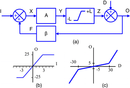
The effect of limits is then considered, using the diagram of , where in effect the output of the ‘A’ block is kept within ±L. This is analysed by considering the response to I and D separately. Where the signals are small enough such that no limiting occurs, the forward over one minus loop rule applies and can be used to find the value of I or D when the signal Y equals L. If this input is then exceeded, Z remains fixed so either O remains constant if the input is I, or O rises linearly. and 6c shows how O varies with I and D when A = 50, β = −0.1 and L = 25.
This completes the initial lectures on feedback. For the rest of the term students are taught a.c. circuits where signals are assumed to be sinusoidal, and complex impedances are introduced for capacitors and inductors. Different circuits are analysed, both first and second order, and Bode plots of the systems introduced. For second-order filters, the resonant frequency and Q factor are introduced.
Frequency response of systems
When the feedback lectures resume, four lectures are used to integrate the circuits material into feedback systems. Initially the circuits and associated block diagrams in are used. The potential divider in with a current load is shown to be like a control system with a disturbance, and ‘forward over one minus loop’ and superposition are used to relate VO to VI and IL. The RC circuit in is then introduced, and the associated block diagram drawn where VO equals 1/C times the integral of the current.
When the input is a sinusoid, then all other signals are sinusoids of the same frequency. For , numerical transfer functions suffice, but for , in addition to the amplitude of the sinusoids, the analysis needs to consider phase shifts so the capacitor is represented by a block with transfer function 1/jωC. The transfer function of the circuit in is found as:
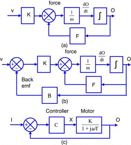
The motors in are then considered. In a force is generated, proportional to the applied voltage: this is opposed by a frictional force, proportional to the motor velocity. The net force divided by the motor mass gives acceleration which is integrated to give the output velocity. shows a multi-loop system, where the current is determined by the difference between the applied voltage and the back emf. shows a motor in a feedback control system.
It is shown that these motors and the RC circuit can be modelled by the first-order transfer function.
Then, if I is sin(ωt), then the modulus and argument of the transfer function can be used to find the output O:
Polar plots and Bode diagrams are used to show what happens when ω is varied, complementing what was taught in a.c. circuits, but inherently showing that the concept applies to non-electronic systems. Asymptotic approximations of the gain and phase plots are also described.
Time domain analysis
The focus then moves to time domain analysis of first-order systems. An intuitive approach is taken initially to allow students to understand the concept using little mathematics. This is achieved by considering how signals change at discrete regular intervals, as if there was computer control, in an approach consistent with CitationCortes and Dunbar (2007).
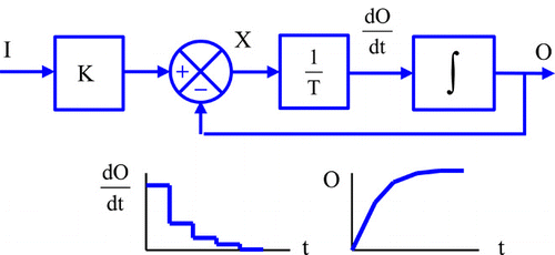
The block diagram of the first-order system in is used, where I is a constant and initially O is zero. Then X and are large so O rises rapidly. At the next instant X and
are less, so O rises by a smaller amount. This continues with O approaching a constant value, as shown in . The concept of steady-state and transient responses is introduced.
It is then shown that, as the interval between updates becomes smaller, so the response becomes smoother, ultimately the output being
It can be seen from the block diagram that , and hence the expression for O is a solution to that differential equation. This is confirmed in the mathematics module.
It is noted that jω has been used to mean differentiation of sinusoids, but for other signals, the Laplace operator s can be used. As such the differential equation is rewritten as sO = (KI – O)/T and rearranged to give the transfer function
This is confirmed by using 1/s to represent the integrator in and using the ‘forward over one minus loop’ rule. It is noted that impedances of electronic components can be represented in terms of s as well as jω.
It is then shown that, just as the steady-state sinusoidal output can be found from the complex transfer function, the steady-state output when the input is a step is found by setting s to zero in the transfer function.
It is then argued that that the time constant of the exponential transient response can also be found from the transfer function: using the ‘root’ of its denominator. It is stated that the transient response also applies when the input is a sinusoid. This ‘informal’ approach provides a gentle introduction to the use of Laplace Transforms.
Simulation
The next stage is to consider how to simulate systems. Rectangular integration is first used, building on the earlier explanation of the time response. It is then shown how MATLAB’s ode45 function gives a more accurate response, using a function written to calculate the differential of O. The simulated responses for step and sinusoidal inputs are found and compared with the theoretical responses.
Second-order systems are introduced, including a motor with an extra integrator whose output is its position, a mass-spring system and an LCR circuit. It is demonstrated how these systems can be represented by first-order differential equations involving two variables (position and velocity of the motor or voltage and current in the LCR circuit). Thence ode45 is used utilising a function which returns a vector containing the differential of those variables. Specific component values are chosen to provide examples of over-damped, critically and under-damped responses.
Second-order systems
It is shown that the steady-state step response of these systems is again determined by setting s to zero in the transfer function, and the transient response is found from the ‘roots’ of its denominator. Examples are given with two real roots giving an over-damped response, and complex roots giving an under-damped response. The parallel mathematics module teaches how differential equations can be solved to produce equivalent responses using the same examples.
The notation associated with undamped natural angular frequency and damping ratio is then described. Damping ratio is related to the Q factor in circuits, and it is shown for instance that a system is under-damped if the damping ratio is less than unity.
Finally
The course is completed by showing how MATLAB can be used to model ‘animal’ systems. This is there to reinforce Wiener’s definition of cybernetics, but also to show that simulation of feedback systems has application in biological domains.
Simple population models are first described. Then interacting systems are considered including the classic fox–rabbit system, an example of predator–prey. Again this is described by two first-order equations.
Course evaluation
One bonus to the reorganised module is that the a.c. circuits material now coincides with the teaching of complex numbers in the mathematics module the students also do, and that the time domain analysis coincides with the teaching of differential equations. The same numerical examples of second-order feedback systems are analysed in feedback and in mathematics.
Another bonus is students are introduced to the representation of integration by 1/jω before 1/s. This is more readily understandable, the author believes, in that ω has a physical ‘meaning’ being the angular frequency of sinusoids. Judging by comments at ACE 2013, this is less useful as regards control for chemical engineers for whom frequency response is not relevant.
The students were surveyed about the lectures. Their responses are shown in .
Table 1 Response to questions.
The self-assessment questions allow the students multiple attempts and feedback is provided when they get the wrong answer. They are also asked to reflect on how confident they are with their answer. This is aimed at helping the students with their learning, and is consistent with the approach described in CitationBenjamin (2013). One student commented on them saying they were “useful when revising midweek [between lectures]. It lets me see if I need to focus more on a topic.”
In past years, the average mark for the electronics module was low and it was hoped that the mark for the new module would be higher. For students for whom the module was compulsory there was a slight improvement, but many students for whom the module was an option struggled or did not engage in the module, attempting only a few of the weekly quizzes. In consequence, students are now advised not to take the module unless they feel confident in mathematics and physics. Also, personal tutors are asked to discuss work, including such quizzes, with their tutees.
Conclusions
The module outlined here integrates the teaching in the first year of feedback, control and electronics in a coherent manner, which could be incorporated in many engineering degrees. The electronics material benefits from the analysis of feedback systems, and the electronics provides some of the examples which demonstrate the relevance of the feedback material. In addition, the concept of feedback and its application is demonstrated using a great variety of systems, showing how it applies in multiple disciplines. The paper has also shown how the design of such an integrated module can help when teaching time is reduced.
References
- Benjamin, C. (2013) Feedback for enhanced student performance: Lessons from simple control theory. Available at http://www.heacademy.ac.uk/assets/documents/subjects/engineering/Engineering_Journal/benjamin_EE_7-2.pdf.
- Black, H.S. (1934) Stabilized feed-back amplifiers. Electrical Engineering 53 (1), 114–120.
- Bunce, D.M., Flens, E.A. and Neiles, K.Y. (2010) How long can students pay attention in class? A study of student attention decline using clickers. Journal of Chemical Research 18 (12), 1438–1443.
- Cortes, J. and Dunbar, W.B. (2007) A high school-level course in feedback control, a MATLAB- based introduction requiring only algebra and trigonometry. IEEE Control Systems Magazine, pp79–89.
- Leigh, J.R. (1992) Control theory a guided tour. IEEE Control Engineering Series 45.
- Mitchell, R.J. (2010) Introducing control using little mathematics. In Proceedings of the UKACC International Conference on Control 2010, 7–10 September, Coventry University, pp728–733.
- Mitchell, R.J. (2012) Available at http://blogs.reading.ac.uk/engage-in-teaching-and-learning/2012/12/19/blackboard-quizzes-to-help-students-to-be-prepared-for-laboratory-practicals-by-dr-richard-mitchell/.
- Mitchell, R.J., Warwick, K., Browne, W.N., Gasson, M. and Wyatt, J. (2010) Engaging robots: Innovative outreach for attracting cybernetics student. IEEE Transactions on Education 53 (1), 105–113.
- Mitchell, R., Harwin, W., Cadenas, O., Guy, G., Gong, A., Potter, B. and Warwick, K. ( eds.) (2011) Cybernetics, Circuits and Computing. Oxford: Pearson.
- Rossiter, J.A., Giaouris, D., Mitchell, R.J. and McKenna, P. (2008) Typical control curricula and using software for teaching/assessment: A UK perspective. In Proceedings of the 17th World Congress, IFAC, Seoul, Korea.
- Usher, M.J., Buckner, I.W. and Burch, R.F. (1977) A miniature wideband horizontal-component feedback seismometer. Journal of Physics E: Scientific Instruments 10, 1253–1260.
- Watson, A.J. and Lovelock, J.E. (1983) Biological homeostasis of the global environment: The parable of Daisyworld. Tellus 35B, 286–289.
- Wiener, N. (1948) Cybernetics or Control and Communication in the Animal and the Machine. Cambridge, MA: MIT Press.
- Williams, K.C. and Williams, C.C. (2011) Five key ingredients for improving student motivation. Research in Higher Education Journal, 121–123.
