Abstract
Advanced control concepts present a teaching challenge, where even at master level students benefit from these concepts being implemented and demonstrated on real hardware, rather than simply modelling the plant, applying control strategy and tuning. This paper describes one of a series of three experiments demonstrating the implementation of different control strategies using adaptive cruise control (ACC) on robot models and real robots. The experiment described here utilises the model predictive control (MPC) strategy implemented in ACC. The algorithm is realised using the graphical programming language (LabVIEW) as the design environment and National Instruments Robotics Starter Kit robot as the target hardware, with the code being deployed on a field programmable gate array (FPGA), included in the robot’s architecture.
Two robotic vehicles, ‘the leader’ and ‘the follower’ are programmed to execute ACC: the velocity of the leader robot and the distance between the robots are augmented into the robot’s state-space equation, to design the controller (MPC), which was then tuned for both velocity and distance tracking modes.
The experiment offers a novel idea on how to deliver this advanced control strategy in an applied and visual manner with laboratory experimentation supporting the theoretical aspects of learning. It brings to life some often stated theoretical qualities of an MPC controller, including quick rise time, minor fluctuation and a small distance tracking error, in line with current scientific papers. Thus, it demonstrates to students a clear correlation between theoretical expectations and real-life system performance whilst challenging their ability to work with real hardware.
Introduction
Recent developments in the field of graphical software and electronic rapid prototyping tools, coupled with increased affordability, offers new opportunities to create experiments for teaching advanced control strategies to engineering students (Gennert & Tryggvason 2009, CitationHwang 2011). In the past, many universities treated research and teaching as two separate parallel entities with little integration of research into teaching, but nowadays there is a strong drive to develop these links. There are different interpretations of the link between teaching and research in universities and how they contribute to the student learning (CitationBrew 2003, CitationSenaratne & Amartunga 2009). Undergraduate research initiatives in Engineering are usually seen as enquiry-based learning. Enquiry tasks can be designed to explore existing knowledge and build new knowledge through analysis and experimentation. However, graduate engineers involved in control design and implementation must be able to apply the concepts learnt at university to solve industrial problems. Thus the learning has to be not only research informed but also needs to address the full industrial design cycle from system identification and modelling to control strategy design, tuning and evaluation. Both enquiry- and problem-based learning may lead to constructing the subject knowledge only (CitationMills & Treagust 2003). Research methods and skills should therefore not only be progressive but a variety of methods and skills should be delivered. One interesting example has been adopted at Herriot-Watt University, where students contribute to the design of laboratory experiments, carry them out, acquire the data, analyse it and compare the results at different levels (CitationJenkins & Zetter 2003, CitationJenkins & Healey 2005). Following that example, a number of our postgraduate students at Kingston University (MSc and PhD levels) were employed to develop research informed teaching materials including hands on experiments and virtual learning to enhance teaching of control-based subjects. The work presented in this paper has been developed by a PhD student and it is informed by his own research (CitationShakouri 2012, CitationShakouri et al. 2012b).
The material is designed for postgraduate students taking the master level module Control Systems with Embedded Implementation, learning how to realise advanced concepts related to sensing methods, robotics and control, using a graphical programming environment with a real-time single board computer. Although primarily designed for the delivery of control systems with embedded implementation concepts, this material can be used for teaching at different levels to students on a range of master level courses, with a different focus, depending on the prior knowledge and the field studied. For example, this material can follow on from the classical control systems and digital electronics, and assumes familiarity with discrete-time linear models and field programmable gate arrays (FPGAs), such as Mechatronic and Embedded Systems courses. Alternatively, it can be taught to Automotive Engineering students, often with limited control and electronics backgrounds, particularly in terms of the state space model and FPGAs. In this case students are provided with the relevant program to run, tune and then analyse system performance.
The teaching experiment described in this paper is one of three in the series aiming to deliver the embedded implementation of different control strategies, in order to appreciate the advantages and disadvantages of each approach. The series uses adaptive cruise control (ACC) with the following three control strategies: classical control (proportional-integral-derivative, PID), fuzzy logic and model predictive control (MPC). All of the experiments introduce students to the implementation of a control method through demonstration of the performance of an ACC algorithm using two real robotic vehicles, which is the subject of a related paper (CitationShakouri et al. 2013). The implementation is based on LabVIEW as the software platform and robotics starter kit from National Instruments (NI) as the control plant in the following scenario: two identical robotic vehicles, ‘the leader’ and ‘the follower’, are programmed to maintain a certain distance from the ‘leader’ using ACC. Graphical programming is beneficial as it does not deter from the main learning goal, demonstrating the performance of an ACC system due to a specific control strategy. This paper describes how to implement MPC based ACC in a robotic vehicle and the evaluation of its performance, starting with a description of the experimental environment and description of the assessment task set for the students in the second section of this paper. The third section starts with system identification result in the form of a transfer function model, followed by the full controller design procedure using switching rules, including reference to the constraint on the controlled input, future set-point trajectory and the resulting tuning parameters. [Students are instructed to use a simplified program based on a single MPC for operation of the ACC in both velocity and distance tracking modes, with the focus on the automated switching between modes of operation, i.e. velocity tracking (CC) and distance tracking (ACC).] The fourth section deals with testing scenarios: students are required to compare and evaluate the results obtained from the simulation and those from running the code on the real robot. An example discussion based on the results of the ACC system simulation controlling a robot model and the results of the deployment on the real robot, implemented in an on-board LabVIEW FPGA module is also provided in this section. The fifth section draws conclusions about the experiment in terms of its content and value for students, helping to appreciate the importance of theory-based simulation, as it offers a good correlation between the theoretical expectations and real-life system performance of the MPC controller used in the ACC system: quick rise time, minor fluctuation and a small distance tracking error, in line with current scientific papers.
The experiment
The software and hardware setup
Graphical programming environment, based on LabVIEW is used for both, simulation and real-life experiment:
During simulation stage, LabVIEW is simply used as the chosen programming language to model the robot, implement the control strategy and to provide stimulus in order to tune simulated performance.
The real-life experiment uses NI Measurement and Automation Explorer to establish the communication link between the host computer (used for programming) and the real-time target, NI starter kit robot (see ) (used for execution). The Project structure within the LabVIEW environment is used to establish the relationship and the hierarchy between all of the hardware and software system components used in the experiment (sensor analogue input, FPGA, motor analogue outputs, control algorithm, etc.). This setup can be run in two modes: as hardware-in-the-loop (HIL) with the NI starter kit robot being the hardware controlled by the host computer, or after download, the robotic vehicle can be used as a stand-alone real-time system, executing the control program independently.
Figure 1 The National Instrument (NI) starter kit robot (CitationNational Instruments 2011).
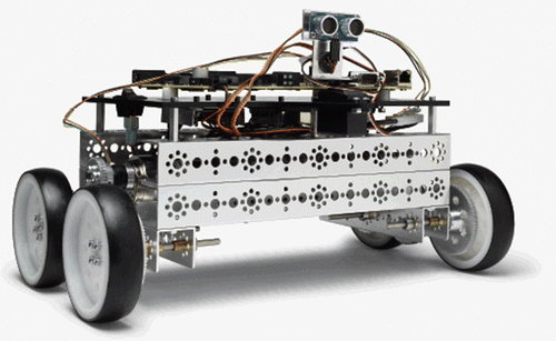
The NI starter kit robot is based on a NI single-board RIO (NI sbRIO-9632), which is used in industry for electronic rapid prototyping and small series systems for embedded control and data acquisition. The board has a Freescale real-time processor, Ethernet connectivity, on-board 2M gates Spartan FPGA, and integrated on-board analogue and digital inputs and outputs. The robot ‘follower’ uses a pre-installed ultrasonic sensor (2 cm to 3 m sensor range) and two 12 V d.c. (direct current) brushed motors, (linear velocity of approximately 0.9 m/s) for velocity and distance tracking of the ‘leader’. The robots can be programmed by using either the high-level LabVIEW robotic starter kit API or by using the LabVIEW FPGA module (CitationNational Instruments 2011).
The curriculum and assessment
Students are given a set of formal lectures and analytical tutorials, covering advanced control and advanced cruise control concepts, the real-time embedded system environment (Compact RIO) and the graphical programming using LabVIEW. (All of the students either participated in the introductory control systems module or have a control background.) The module learning objectives are to specify, design and implement a control strategy to optimise real-time embedded system performance using modern software design techniques. The course is assessed 100% by coursework, with this section, related to the design and implementation of automated speed-dependant electronic control unit (ECU) function for safe distance-keeping of an electric vehicle accounting for 50% of the total marks.
The students’ brief is to design and implement ACC with the slave vehicle model required to maintain a set distance whilst following the master vehicle’s speed profile (pseudo-random) for simulation. The design has then to be implemented and verified using a real robotic vehicle, NI starter robotic kit, following the same pseudo-random speed profile, for comparison purposes. Different teams are instructed to use different control strategies, one of them being MPC. In order to determine the safe distance, they needed to take into consideration the distance between the leader and the follower.
The assessment brief is as follows:
Design an ACC algorithm using LabVIEW, based on the transfer function model of the robot (from system identification).
Obtain an optimized solution using simulation with control strategy of your choice, in order to perform ‘the leader’ and ‘the follower’ action (maintaining a set distance).
Investigate the construction and operation of the real robot (NI robotic starter kit), including the incorporated sensors and actuators.
Investigate a programming method for a real-time embedded FPGA based system.
Apply the ACC strategies developed in 1 and 2 to a real robot.
Compare the system performance to discuss the correlation between the performance of the robot model and a real robot. Discuss the problems and discrepancies introduced by a real system.
Discuss and compare the performance of your robot with the other teams, using different control strategies.
Introduction to the software and hardware is done individually, to ensure that every student gets the chance to learn the software and become equipped to work independently. However, collaborative learning is used for the coursework and teams typically consist of students from different courses, benefiting from the interdisciplinary specialism of group members.
Controller design process
System identification
In order to design a controller, the model describing the dynamic behaviour of the system needs to be identified, i.e. starter kit robot. The system identification process involves acquiring data from a real-world system, then numerically analysing stimulus and response data to estimate the parameters of the plant. LabVIEW System Identification Toolkit is used to estimate the model reflecting the dynamic behaviour of the system based on the acquired data. The robot model transfer function approximated through the model identification process (demonstration), is given to students (due to time constraints) and can be presented as (CitationShakouri 2012, CitationShakouri et al. 2012b):
ACC and CC modes based on MPC-design procedure
Student groups are directed to go through the full design procedure, using lecture and tutorial notes and reference materials listed in this paper.
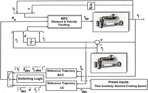
As per brief, the ACC system is designed to operate in two different modes, depending on the situation in front of the follower robot: distance tracking and velocity tracking modes (CitationRajamani & Zhu 2002, CitationShakouri et al. 2012a). If the ultrasonic sensor of the follower robot (ACC equipped) detects a slower moving robot in front, the controller adjusts the follower robot’s velocity to maintain the desired distance. If there is no subject detected by the ultrasonic sensor, it will switch to velocity tracking mode known as cruise control (CC) mode in order to track the desired specified velocity.
The switching logic has to be devised to implement automated switching between the two modes of operation for the ACC system, i.e. velocity tracking (CC) and distance tracking (ACC) modes (CitationRiis 2007, CitationShakouri & Ordys 2011, CitationShakouri et al. 2011, CitationShakouri et al. 2012a). The switching rules for transition between CC and ACC modes are illustrated in .
Table 1 Logical rules for switching between CC and ACC modes.
The desired headway distance d des can be computed using the following equation assuming that the follower and leader robot have the same speed (v f = v l), which is known as Constant-Time Headway policy (CitationZhou & Zhang 2003, Citationvan den Bleek 2007, CitationXiao & Gao 2010):
where l is the robot length, ds is the additional distance between two robots in order to avoid collision, vf is the follower robot’s velocity and Th is the constant-time headway that approximates system reaction time, i.e. 1–2 s. In the simulation, the distance between the follower and leader robots is obtained by Equation 3, while an ultrasonic sensor is used for measuring the distance for real implementation:
In order to design an ACC system utilizing a single MPC which would be capable of carrying out distance and speed tracking control simultaneously (see ), the state-space equation of the overall system is created based on the method proposed in CitationShakouri et al. (2012b). This model is developed by augmenting the robot dynamics model of the ‘follower’ (equipped with an ACC system) and the dynamics due to interaction between the two robots: speed and distance tracking. The state-space equation of the robot in discrete-time form can be obtained by converting from transfer function (Equation 1):
where vsp is the robot’s velocity setpoint as a system input. The states of the system (follower robot) are acceleration and velocity, as . The system output y (robot velocity) can be obtained by having
(the subscript ‘dis’ stands for discrete-time).
The state-space equation of the overall system also includes the velocity of the leader robot and the distance between the robots, i.e. (subscript “augd” stands for the augmented equation in discrete-time form):
The state-space equations and their coefficients integrating the dynamics of the robotic vehicle and the dynamics of tracking can be defined as following equations in discrete-time:
The numerical values used are:
In the ACC system, MPC computes the optimal controlled input such that the output parameters of the system, i.e. , reach the desired set-point determined by the vector Rs. To find the optimal solution for the system with one input and three outputs in MPC context, the output vector y can be decoupled into three separate outputs y1, y2 and y3 as alternated below (CitationShakouri 2012, CitationShakouri et al. 2012b):
The state-space equations of the system can be extended by taking the integral action into consideration to obtain the incremental model as follows (CitationWang 2009, CitationShakouri 2012):
where Δxaugd(t) and Δvsp(t) are respectively the differences of the states and control variable and are given as Δxaugd(t) = xaugd(t) − xaugd(t − 1), and Δvsp(t) = vsp(t) − vsp(t−1). The subscripti = 1, 2, 3 indicates the sequence of elements in output vector (Equation 8). As such, three incremental matrices need to be calculated with respect to the sequence of the elements in the output vector.
Consequently, the optimal control vector ΔVsp i.e. , can be obtained:
Having Δvsp calculated within the control horizon N, the vector containing the absolute values of the control signals can be calculated as the following vector:
The vector Vsp will be calculated at each instance of the time, and the first element of the vector will be sent to the system.
Advanced control concepts (points to address)
Constraint on the controlled input (to be explained during the control design stage)
The ACC has the task to control the longitudinal and forward motion of the robot with a minimum and maximum linear velocity set-point of the robot restricted to within 0 ≤ vsp(t) ≤ 0.9 m/s. The constraint to be imposed on the controlled input is calculated using Hildreth’s Quadratic Programming (CitationWang 2009). The optimization problem is solved by taking into account the constraint on the amplitude of the control variable. Details of how the constraint is incorporated within MPC context are stated in (CitationWang 2009, CitationShakouri 2012, CitationShakouri et al. 2012b).
Future set-point trajectory (to be explained during the optimisation stage)
The reference set-point Rs is required for calculation of the control sequence of the MPC. The reference trajectory is different, depending on the system mode of operation (ACC or CC mode). Based on the output equation of the system given by Equation 8, three outputs are the follower robot’s velocity vf, the distance d and the relative speed vr. When the system is in the CC mode, the only parameter being of concern is the robot speed, while the relative speed and the distance do not need to follow a reference trajectory, i.e. are ‘free’. However, when the system operates in the ACC mode, the relative velocity and the distance are important parameters while robot speed is ‘free’. To perform optimisation numerically, we must make sure that the performance index is not optimised with respect to those variables which do not need to follow a reference. The way of achieving that is by setting the appropriate reference signal equal to the predicted future values of those ‘free’ variables.
The future values of reference signals are generated for each mode: (a) CC mode uses the predicted desired cruising speed , the predicted distance
and the predicted relative velocity
; (b) ACC mode uses predicted robot speed
, predicted desired distance
and predicted desired relative velocity
.
Tuning parameters (to be explained during the tuning stage)
The weighting matrices ,
,
,
and the value of the prediction horizon N for the two modes of operation (CC and ACC) are tuned to achieve the better results. The values for those parameters are given in .
Table 2 The tuning parameters of MPC.
Testing scenarios and results
Testing scenarios
The students are requested to test and collect data for the designed ACC system in both tracking modes:
Distance tracking (ACC) mode: The system operates in the ACC mode, when the robot equipped with ACC approaches the robot travelling slower in front to retain the desired distance between vehicles.
Velocity tracking (CC) mode and switching mode: The system operates in CC mode, when either the distance between the robots is greater than the desired distance or the leader robot speed becomes higher than the desired cruising speed. Depending on the condition occurring in front of the follower robot, the system can switch between ACC and CC modes.
The results (for instructors)
The results obtained from the simulation and those from running the code on the test robot are to be compared and evaluated. Thus, for the purpose of comparison and being consistent for all executed tests, the leader robot has been virtually defined in the software by introducing the sinusoidal signal for the leader robot’s velocity. In this way, the distance between robots can be calculated from Equation 3.
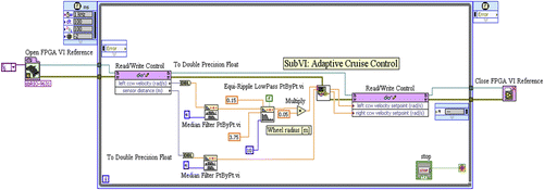
shows an example ACC algorithm utilising MPC, developed and later tested on the real robot, using on-board LabVIEW FPGA module.
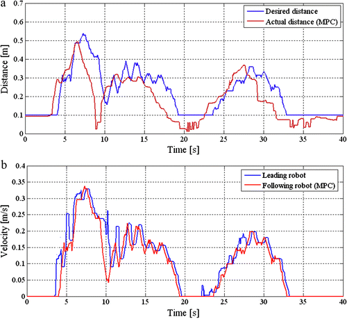
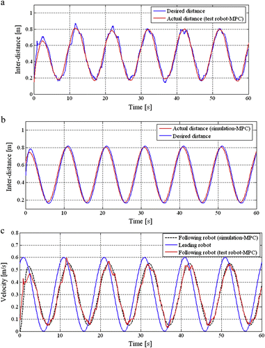
shows the results using the MPC for distance tracking (ACC) mode. Based on the test, the minimum safe distance d0 and time-constant headway Th were chosen to be 0.1 m and 1.3 s, respectively. The tests of the two control applications on the operation of the ACC system have been compared. shows that the results obtained from the test on the starter kit robot are close to those from the simulation. Some slight undulations may be observed on the desired distance curve, which is because the desired distance is a function of the follower robot velocity; and therefore its variation depends on the velocity. However, the ACC system operates very well at distance tracking.
Figure 4 Distance tracking (ACC) mode using MPC: (a) the inter-distance between the robots using test robot; (b) the inter-distance between the robots from simulation implementation; (c) the velocities obtained during distance tracking using test robot and from simulation implementation.
It can be shown that for the robot velocity tracking mode utilising the MPC, robot velocity quickly reaches the desired cruising speed which in turn causes the inter-distance to decrease to the less than desired distance. Because of that, within approximately 0–23 s the system operates in the switching mode (ACC and CC); therefore in some region it tries to track the distance rather than velocity. After 23 s the velocity tracking is fulfilled very well, as per .
Figure 5 Velocity tracking (CC) and switching modes using MPC: (a) the velocities obtained during distance tracking from test robot and simulation implementation; (b) the distance during velocity tracking utilising real robot; (c) the distance during velocity tracking obtained from simulation.
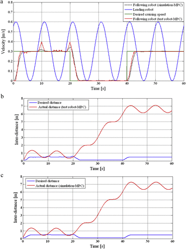
shows the results obtained by utilising two robots corresponding to leader and follower robots. The distance between the robots has been measured through an ultrasonic range finder which uses acoustics to measure the distance, by analysing the time taken when the signal is sent through an emitter, bounces back from the surface and is received back. The ultrasonic sensors are not very accurate when used for reading distance - the measurement can be affected by reflectivity of the different surfaces and environment. In order to mitigate sudden variations of the distance, which in turn degrades the controlling process, a Median Filter was used within the program algorithm, right after the sensor distance port of the Read/Write Control block of the LabVIEW FPGA interface (as shown in ). The distance and velocity tracking were carried out by a single MPC.
Discussion and conclusions
The experiment described in this paper is part of a series of experiments proposed for the delivery of a range of control concepts from PI and PID to fuzzy logic and MPC, using ACC and robotic vehicles. This paper describes the experiment designed to demonstrate advanced control strategy (MPC) in a specified ACC algorithm for modelling, simulation and hardware implementation (robotic starter kit). It includes an assessment brief, design procedure with typical values and a set of experimental results for instructors.
Due to its content and based on student feedback, the experiment gives opportunities for students to develop a wide range of important high level engineering skills, from the ability to use design and simulation tools, and rapid prototyping environment, to gain first-hand experience with HIL testing and tuning. In terms of theoretical knowledge, students are introduced to a range of high-level theory (MPC) whilst related analytical skills (state space calculations) are being developed and tested. The learning can be described as a multi-level process, starting with an appreciation of advanced control theory and analytical implementation, followed by high-level programming for system simulation and tuning, to HIL testing and real-time hardware implementation (including incorporation of real-life issues, such as the need for filtering, for example).
The experiments involving the robotic starter kit were trailed with the master level student groups from Mechatronic Systems, Embedded Systems and Automotive Engineering. Although the students found the experiments challenging, their feedback at the end of the laboratory work was very positive. The evaluation questionnaires were used to quantify the level of perceived personal gain, with scoring done for four question categories (with overall normalised responses given in brackets) evaluating the improvement in: understanding of the underlying theory (80%), interest in industrial technology (83%), transferable skills (78%) and student engagement (75%). The specific comments from many students were related to the value and enjoyment in using the blend of software and hardware in the same experiment. Furthermore they felt that it brought to life control theory. A significant number of students however felt that they could have done with more time to do the experiment, due to the complexity of both underlying theory and implementation hardware. They enjoyed the approach that covered a full design cycle, which will be demonstrated and examined in the assessment for this module, tasking the students to provide a solution to a real-life problem.
Overall, students recognised the fact that this experiment gives them an opportunity to design, tune and test the performance of an advanced controller and to observe the differences between simulated and real-life experiments, whilst identifying additional effects that must be taken into account as these simply do not exist when a system is simulated. Despite the additional challenges and pressures on the educational system associated with this type of curriculum delivery (such as a significant increase of the preparation workload and the teaching time required) there is a significant gain in terms of improved learning and student engagement. Furthermore, the connection between institutional research and real-life, industry-ready knowledge is a strong driver for a wide implementation of this type of instructional method.
References
- Brew, A. (2003) Teaching and research: New relationships and their implications for inquiry-based teaching and learning in higher education. Higher Education Research and Development 22 (1), 3–18.
- Gennert, M.A. and Tryggvason, G. (2009) Robotics engineering: A discipline whose time has come. IEEE Robotics & Automation Magazine 16, 18–20.
- Hwang, H.S. (2011) Rapid prototyping platform for robotics applications. IEEE Transactions on Education 54 (20), 236–264.
- Jenkins, A. and Healey, M. (2005) Institutional Strategies to Link Teaching and Research. York: Higher Education Academy.
- Jenkins, A. and Zetter, R. (2003) Linking Teaching and Research in Departments. York: Learning and Teaching Support Network Generic Centre.
- Kouvariatkis, B., Canon, M. and Rossiter, J.A. (1999) Nonlinear model based predictive control. International Journal of Control 72, 919–928.
- Mills, J.E. and Treagust, D.F. (2003) Engineering education – is problem-based or project-based learning the answer? Australasian Journal of Engineering Education 11, 2–16. Available at http://www.aaee.com.au/journal/online.htm.
- National Instrument (2011) Available at http://zone.ni.com/devzone/cda/tut/p/id/10464 (accessed 15 September 2011).
- Rajamani, R. and Zhu, C. (2002) Semi autonomous adaptive cruise control systems. IEEE Transaction on Vehicular Technology 51 (5), 1186–1192.
- Riis, P. (2007) Adaptive Cruise Controller Simulation as an Embedded Distributed System. MSc Thesis, Linkoping University.
- Senaratne, S. and Amartunga, A. (2009) Principles of integrating research into teaching in Higher Education: Built Environment Perspective. International Journal of Construction Education and Research 5 (3), 220–232.
- Shakouri, P. (2012) Designing of the Adaptive Cruise Control System – Switching Controller. PhD Thesis, Kingston University London.
- Shakouri, P. and Ordys, A. (2011) Application of the state-dependent nonlinear model predictive control in adaptive cruise control system. In Proceedings of the 14th International IEEE Conference on Intelligent Transportation Systems – ITSC 2011, 5–7 October 2011, The George Washington University, Washington, DC.
- Shakouri, P., Ordys, A., Laila, D.S. and Askari, M.R. (2011) Adaptive cruise control system: Comparing gain-scheduling PI and LQ controllers. In Proceedings of the 18th IFAC World Congress, Milan.
- Shakouri, P., Collier, G. and Ordys, A. (2012a) Teaching control using NI starter kit robot. In Proceedings of the UKACC International Control Conference, 3–5 September 2012, Cardiff.
- Shakouri, P., Ordys, A. and Askari, M.R. (2012b) Adaptive cruise control with stop & go function using the state-dependent nonlinear model predictive control approach. ISA Transaction 51 (5), 622–631.
- Shakouri, P., Ordys, A. and Collier, G. (2013) Robotic implementation of the adaptive cruise control: comparison of three control methods. In Proceedings of the Mechatronics 2013: International Conference, October, Brno, Czech Republic ( eds. T.Brezina and R.Jablonski), pp633–640. Berlin: Springer.
- van den Bleek, R.A.P.M. (2007) Design of a Hybrid Adaptive Cruise Control Stop-&-Go System. Master’s Thesis, TNO Science & Industry, Technische Universiteit Eindhoven.
- Wang, L. (2009) Model Predictive Control System Design and Implementation Using Matlab, 2nd. Berlin: Springer.
- Xiao, Lingyun and Gao, Feng. (2010) A comprehensive review of the development of adaptive cruise control system. Vehicle System Dynamics 48, 1167–1192.
- Youssef, A.M., Ordys, A.W. and Grimble, M.J. (2004) Nonlinear predictive control for fast constrained systems. In Proceedings of the IEEE Conference on Methods and Models in Automation and Robotics, August, Miedzyzdroje, Poland.
- Zhou, W. and Zhang, S. (2003) Analysis of distance headways. In Proceedings of the Eastern Asia Society for Transportation Studies 4, 556–561.
