
Abstract
Transient liquid phase (TLP) brazing of Mg–AZ31 alloy and Ti–6Al–4V alloy was performed using double Ni and Cu sandwich foils. Two configurations were tested; first, Mg–AZ31/Cu–Ni/Ti–6Al–4V and second, Mg–AZ31/Ni–Cu/Ti–6Al–4V. The effect of set-up configuration of the foils on microstructural developments, mechanical properties and mechanism of joint formation was examined. The results showed that different reaction layers formed inside the joint region depending on the configuration chosen. The formation of ϵ phase (Mg), ρ (CuMg2), δ (Mg2Ni) and Mg3AlNi2 was observed in both configurations. Maximum shear strength obtained was 57 MPa for Mg–AZ31/Ni–Cu/Ti–6Al–4V configuration and in both configurations, the increase in bonding time resulted in a decrease in joint strength to 13 MPa. The mechanism of joint formation includes three stages; solid state diffusion, dissolution and widening of the joint, and isothermal solidification.
Introduction
Transient liquid phase (TLP) brazing has been used as a preferred joining technique to bond various advanced metals and dissimilar alloys.Citation1–Citation7 The ability to join a titanium alloy (Ti–6Al–4V) to a magnesium alloy (Mg–AZ31) can open up new avenues for product development. The Ti–6Al–4V alloy has been an attractive alloy for aerospace, marine, and chemical industries. Furthermore, it has high strength to weight ratio, low thermal conductivity, and good corrosion resistance.Citation8,Citation9 The Mg–AZ31 alloy has also received increased attention for use in the electrical and automotive industries, because of the Mg–AZ31 having high strength to weight ratio and good conductivity.Citation10–Citation12 The literature showed that various single metallic foils have been used and applied to enhance joint formation in TLP brazing.Citation2,Citation3,Citation10–Citation14 Furthermore, it showed that copper and its alloys have been used as eutectic forming interlayers in diffusion and TLP brazing of titanium, magnesium and dissimilar alloys systems.Citation2,Citation15–Citation20 In prior work, Ni foils were tested as a eutectic forming interlayer to enhance joint formation between Ti–6Al–4V and Mg–AZ31.Citation21–Citation23 On the other hand, the copper foil produced a eutectic liquid at a temperature lower than the eutectic temperature for Ni–Mg (TE Mg–Cu = 485°C and TE Mg–Ni = 512°C).Citation24,Citation25 The formation of hard intermetallic phases between the magnesium alloy Mg–AZ31 and nickel foil can detrimentally affect the joint shear strengths and compositional homogeneity. Therefore, it was considered that a combination of Cu and Ni foils could result in fewer intermetallics forming inside joint region, bonding could be performed at a lower temperature and this combination of parameters would enhance the joint shear strength. Therefore, an alternative technique of double sandwich Ni and Cu foils was considered to bond the Ti–6Al–4V and Mg–AZ31 alloys.
In this study, the novel aspects of TLP brazing of Mg–AZ31 and Ti–6Al–4V were studied using two configurations; first, Mg–AZ31/Cu–Ni/Ti–6Al–4V and second, Mg–AZ31/Ni–Cu/Ti–6Al–4V. The relationship between microstructure, compositional analysis and mechanical properties on the mechanism of joint formation was established.
Experimental Procedure
Commercially available titanium alloy (Ti–6Al–4V) and magnesium alloy (Mg–AZ31) were used in this study. The chemical composition of Ti–6Al–4V alloy was 6Al–4V–90Ti (wt-%). The Ti–6Al–4V and Mg–AZ31 alloys were obtained from Goodfellow (Cambridge, UK) in the form of extruded rod of 10 mm diameter. The chemical composition of Mg–AZ31 was 3Al–1Zn–96Mg (wt-%). Before TLP brazing, 5 mm thick samples of Ti–6Al–4V and Mg–AZ31 alloys were cut and surfaces prepared by grinding and polishing down to 1000 grit SiC paper and then cleaned with ethanol. Thin foils (20 μm) of pure nickel and Cu were used as interlayers. The Ti–6Al–4V samples were pickled in diluted HCl solution of (20%HCl–80% distilled water) for 3 min, the Ni and Cu foils were pickled for 1 min to remove surface oxides and degreased in methanol. Two configurations were tested in this study, namely, Mg–AZ31/Cu–Ni/Ti–6Al–4V and Mg–AZ31/Ni–Cu/Ti–6Al–4V at a range of bonding time from 5 to 60 min. Transient liquid phase bonding was carried out using induction heating with a rate of 50°C min−1. Furthermore, a vacuum chamber with a pressure of 4×10⁻⁴ Torr (0·053 Pa) was used. The bonding temperature was set as 515°C; bonding pressure of 0·35 MPa was used to hold the bonded samples and to provide surface to surface contact between the foils, Ti–6Al–4V and Mg–AZ31 alloys, and three samples were bonded for each bonding condition. Transversely cross-sections through bond region were prepared by using standard metallurgical techniques with a final surface polish using a 1 μm SiC suspension (prepared according to the ASTM standard E3-01). The microstructure of the bonded samples was observed using electron microprobe analyser SEM (JEOL JXA 8200) equipped with wavelength dispersive X-ray spectroscopy and energy dispersive X-ray spectroscopy (EDS) for composition analysis. A Vickers microhardness test was carried out using a Shimadzu miniload microhardness tester. A microhardness traverse was established with 600 μm on each side and 50 g of load, and nine microhardness readings were measured. The shear strength measurements were carried out using a 25 kN load cell tensile testing machine (Tinius Olsen H25KS) at a crosshead speed of 0·5 mm min−1. X-ray diffraction (XRD) was performed to study the phase composition and intermetallic compounds formed inside joint region at both alloys Mg–AZ31 and Ti–6Al–4V fractured surface. A Rigaku Multiflex Cu K radiation source with a step size 0·1° and step time 5 s is used at 40 kW and 20 mA over a scanning range of 10–90° 2Φ.
Results and discussion
Microstructural development
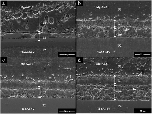
The SEM micrograph of joint interface for Mg–AZ31/Cu–Ni/Ti–6Al–4V made at 515°C for different bonding times is shown in . At bonding times less than 10 min all bonds failed to produce a joint and failure was seen at the Ni and Ti–6Al–4V interface. Furthermore, at short bonding times, less diffusion of Cu and Mg to the Ni/Ti–6Al–4V interface was observed. At a bonding time of 10 min, the Cu–Mg eutectic formed and reacted with the Ni interlayer. This reaction resulted in the dissolution of the Ni foil to form two reaction layers L1 and L2 inside the joint region. A maximum liquid width of 132 μm was observed ( and ). Increasing the bonding time to 20 min resulted in a decrease in the joint width to 75 μm ( and ). This was attributed to the increase in the outward diffusion of Mg which resulted in partial solidification of liquid within the joint. Further increase in the concentration of Mg resulted in a new liquid eutectic of Ni–Mg forming in the joint. The chemical composition 43 wt-%Ni, 25 wt-%Mg, 13 wt-%Al and 5 wt-%Cu was noticed within the L2 reaction layer (). The reaction layer L2 contains a partial zone L2’ with a chemical composition of 51 wt-%Ni, 31 wt-%Mg, 12 wt-%Al and 2 wt-%Cu as shown in and . Further increase in bonding time to 30 min resulted in slight decrease in joint width to 71 μm. The reaction layers L1 and L2 were observed in the joint ( and ). The increase in the width of L1 can be attributed to the dissolution of parent alloy P1 (Mg–AZ31) and the formation of liquid eutectic. When the bonding time reached 60 min, the joint width increased to 101 μm ( and ). This was attributed to the formation of eutectic Ni–Mg as indicated in the EDS analysis in .
1. Image (SEM) of Mg–AZ31/Cu–Ni/Ti–6Al–4V joint interface after bonding at 515°C and 0·35 MPa for a 10 min; b 20 min; c 30 min; d 60 min. P1: Parent alloy Mg–AZ31, P2: Parent alloy Ti–6Al–4V, L1: Reaction layer 1, L2: Reaction layer 2
2. Effect of bonding time change in Mg–AZ31/Cu–Ni/Ti–6Al–4V configuration on joint width at 515°C, 0·35 MPa
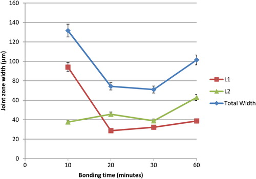
Table 1. EDS analysis for reaction layers indicated in
Table 2. EDS analysis for reaction layers indicated in
The Mg content in reaction layer L1 increased to 80 wt-% and the Ni concentration decreased to 11 wt-%. Furthermore, the composition of L2’ showed an increase in Mg concentration to 57 and 25 wt-%Ni. This composition was comparable to the eutectic composition and is responsible for the increase in joint width.
The starting foil thickness for the single Cu foil was 20 μm, and the double Cu–Ni had an initial thickness of 40 μm. However, during the TLP bonding process the results showed that the double foil resulted in a smaller eutectic joint width. This was attributed to partial solidification of the joint during the bonding process and the change in joint composition resulted in a smaller value of eutectic forming and less dissolution of the parent alloy Mg–AZ31 during the bonding process. The application of double sandwich foils (Cu and Ni) compared to single Ni foilCitation23 resulted in a smaller joint width, as a result shorter diffusion distances within the joint.
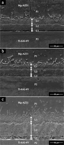
The SEM micrograph of joint interface for Mg–AZ31/Ni–Cu/Ti–6Al–4V made at 515°C for different bonding times is shown in . At bonding times less than 20 min (i.e. 5 and 10 min) all bonds failed to join, and the failure was seen at the Cu foil and between the Ni–Cu interlayer and Cu/Ti–6Al–4V interface. This was attributed to the short bonding time in which the Ni eutectic liquid was unable to completely wet the Cu foil. However, three reaction layers formed and these were labelled L1, L2 and L3. For a bonding time of 20 min, the joint width was 64 μm ( and ). As the bonding time increased from 20 to 30 min the width of the reaction layers L1 and L2 was 66 μm ( and ). Furthermore, the increase in bonding time to 60 min resulted in a joint width similar to the one seen for the Mg–AZ31/Cu–Ni/Ti–6Al–4V with joint width of 111 μm ( and ). This increase in joint width as a result of bonding time was attributed to the increase in Ni–Mg and Cu–Mg eutectic liquid where the increase in Mg concentration was not enough to onset the isothermal solidification of the joint.
3. Image (SEM) of Mg–AZ31/Ni–Cu/Ti–6Al–4V joint interface after bonding at 515°C and 0·35 MPa for a 20 min; b 30 min; c 60 min. P1: Parent alloy Mg–AZ31, P2: Parent alloy Ti–6Al–4V, L1: Reaction layer 1, L2: Reaction layer 2, L3: Reaction layer 3
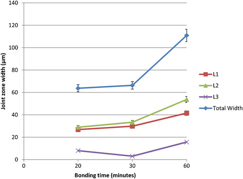
4. Effect of bonding time changes in Mg–AZ31/Ni–Cu/Ti–6Al–4V configuration on joint width at 515°C and 0·35 MPa
shows the EDS analysis of the reaction layers seen in . Reaction layer L1 showed a chemical analysis similar to the one seen when using single Ni foils;Citation20 a high concentration of Mg grains and high Ni concentration at the grain boundary. The reaction layer L2 showed a chemical composition similar to the eutectic concentration as indicated in the Ni–Mg phase diagram. However, the formation of the L3 reaction layer indicated that solid state diffusion between Ni and Ti had occurred at the Ni/Ti–6Al–4V interface, and the presence of concentrations of Ti in L3 confirmed solid state diffusion between Ti and Ni.
Table 3. EDS analysis for reaction layers indicated in
shows the chemical composition of the joint region for bonds made for 60 min. When comparing the bonds made for 20 min with the one made for 60 min, the analysis indicated that the reaction layers L1 and L2 have more Mg and Cu content, while concentration of Ni and Al decreased in the layers. Also L3 showed more Ti diffusion into the joint region, and this observation suggested the continuous solid state diffusion at the Ti alloy interface. The continuous increase in joint width suggested that no isothermal solidification occurred even for a 60 min bonding time. It can be noticed that Mg also diffused into the Ti–6Al–4V alloy (P2) and this was attributed to the higher diffusivity of Mg in Ti than Ti in Mg.
Table 4. EDS analysis for reaction layers indicated in
Solid state diffusion is an important stage required for the formation of a solid/liquid interface during the TLP bonding process. During the heating stage, solid state diffusion is required in order to cause the concentration of Mg, Ni and Cu to reach a suitable value between the liquidus lines in the Mg–Cu and Mg–Ni phase systems. This concentration triggers the TLP bonding process. It is expected that a lack of time to allow an increase in the concentration of Mg at the Cu–Mg/Ni interface caused the two alloys not to bond for the Mg–AZ31/Cu–Ni/Ti–6Al–4V configuration when the bonding time was less than 10 min. The same was observed for the Mg–AZ31/Ni–Cu/Ti–6Al–4V configuration for a bonding time of less than 20 min. The differences in the minimum time required between those two systems (10 min for Mg–AZ31/Cu–Ni/Ti–6Al–4V, and 20 min for Mg–AZ31/Ni–Cu/Ti–6Al–4V) can be attributed to the differences in eutectic forming temperatures in Mg–Cu (483°C) and Mg–Ni (512°C).Citation24,Citation26
However, in both configurations tested in this work the systems are more complex where two steps liquid formation are expected, one at Mg–Ni and the other at Mg–Cu. For the Cu–Ni it is not expected to produce any liquid as suggested by Miettinen for Cu–Ni phase diagram where the minimum temperature for liquid to form is about 1085°C which is above the bonding temperature and the melting temperature of Mg.Citation27
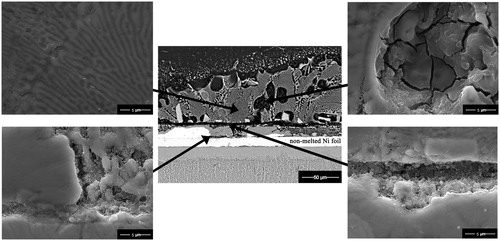
The experimental results showed that the mechanism of joint formation using double foil interlayers involves both solid state diffusion and eutectic formation mechanism occurring simultaneously. shows the SEM for different bond zones inside the joint region of the Mg–AZ31/Cu–Ni/Ti–6Al–4V joint interface after bonding at 515°C and 0·35 MPa for 10 min. The lamellar structure at Mg–AZ31/Cu interface suggested the formation of liquid eutectic between Mg and Cu. On the other hand, the secondary SEM micrograph shows the non-melted Ni foil which suggests the solid state diffusion is taking place.
5. Images (BSE–SEM) of Mg–AZ31/Cu–Ni/Ti–6Al–4V joint interface after bonding at 515°C and 0·35 MPa for10 min
shows the SEM for different bond zones inside joint region of Mg–AZ31/Ni–Cu/Ti–6Al–4V after bonding at 515°C and 0·35 MPa for 20 min. In earlier work by Gupta, he showed only four intermediate phases are possible in the three binary systems of Cu–Mg–Ni. Furthermore, no ternary phases are known to form in this system.Citation28 shows the phase designations with associated composition in Cu–Mg–Ni system.
6. Images (BSE–SEM) of Mg–AZ31/Ni–Cu/Ti–6Al–4V joint interface after bonding at 515°C and 0·35 MPa for 20 min
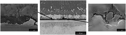
Table 5. Phase designation and composition in Cu–Mg–Ni ternary systemCitation28
Based on the previous work by Gupta, it is expected that two reactions will be dominant on Cu–Mg–Ni system, namelyCitation28
The microstructural observations showed that during the bonding process, the phases CuMg2, Mg2Ni, and Mg3AlNi2 formed as a result of initial solid state diffusion between the foils and Mg alloy. However, at the eutectic reaction temperature of 483°C for Cu/Mg–AZ31 and 512°C for Ni/Mg–AZ31 the formation of these phases would be accelerated. It can be suggested once the Mg phase (ϵ) concentration increased inside joint region, the reaction with Cu and Ni (γ) can be broken down to CuMg2 (ρ) and Mg2Ni (δ) phases within the liquid. Furthermore, Raghavan suggested the formation of Mg3AlNi2 ternary phase between Al, Mg and Ni at a temperature as low as 427°C.Citation29
The solid state diffusion process is dominant at the Cu/Ti–6Al–4V and Ni/Ti–6Al–4V interfaces at all stages of TLP bonding. Bormann suggested a eutectic reaction between Ni and Ti may occur at a temperature higher than 940°C. However, TiNi3, TiNi and Ti2Ni intermetallics can form even at low temperatures.Citation30 Turchanin et al. suggested that the minimum eutectic reaction temperature between Cu and Ti to occur was 883°C. However, Cu4Ti, Cu3Ti2, Cu4Ti3 and CuTi2 intermetallics can also form at a lower temperature of 200°C.Citation31 Hence it can be concluded that solid state diffusion is possible between the Cu or Ni foils at the Ti–6Al–4V interface at a bonding temperature of 515°C.
In the Mg–AZ31/Cu–Ni/Ti–6Al–4V joint configuration it was observed that the dissolution width of the joint region increased from 40 to 132 μm, and then decreased to a width of 71 μm. However, further increase in bonding time resulted in an increase in joint width to 101 μm. This observation suggested that the bonding mechanism for this system at this stage occurred in two steps, first the dissolution of the Cu foil due to the reaction between Mg and Cu which resulted in eutectic liquid formation. A widening of the joint region followed, where the increase in bonding time resulted in an increase in Mg concentration at the joint centre which leads to temporary solidification. The second step involves the reaction between Mg and Ni interlayer which reacted to form a new liquid phase of Mg–Ni eutectic.
On the other hand, in the Mg–AZ31/Ni–Cu/Ti–6Al–4V joint configuration the dissolution and widening of the joint region was continuous up to 60 min. This observation suggested that a continuous reaction progresses between Mg–Ni and Mg–Cu, when a temperature of 515°C is used. This temperature is above the eutectic temperature of Mg–Cu (480°C) and this ensures a continuous increase in joint width until the concentration of Mg changes and result in a reduction of joint width because of isothermal solidification.
The isothermal solidification was seen only in Mg–AZ31/Cu–Ni/Ti–6Al–4V between 10 to 30 min. However, the observation of the microstructure for Mg–AZ31/Ni–Cu/Ti–6Al–4V showed that the joint width continuously increased even for a prolonged bonding time of 60 min. As a result of continuous formation of eutectic liquid no isothermal solidification was observed for Mg–AZ31/Ni–Cu/Ti–6Al–4V system.
Microhardness evaluation
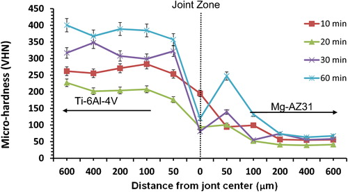
Microhardness profiles for joint interface as a function of time are shown in and . The variation in hardness across the joint gives a good indication to the compositional homogeneity of the joint and distribution of phases forming in the joint. For the Mg–AZ31/Cu–Ni/Ti–6Al–4V configuration, as the bonding time increased the microhardness profile increased inside the Ti–6Al–4V alloy adjacent to the joint interface (). At bonding time of 10 min a transition between the two parent alloys was noticed from 250 to 60 VHN. Inside the joint region, the same observations were seen before when using a single Ni foil. An increase in microhardness at 50 μm from the joint centre towards the Mg–AZ31 alloy, gave a maximum hardness value of 357 VHN for bonds made at a 60 min bond. The microhardness value tends to be similar to the parent alloy Mg–AZ31 value after 200 μm with a range from 50 to 70 VHN for a bonding time of 10 min. The highest microhardness inside the joint region (195 VHN) was achieved at 10 min bond time.
7. Microhardness profile across joint with Mg–AZ31/Cu–Ni/Ti–6Al–4V configuration made at 515°C, 0·35 MPa for different bonding times
8. Microhardness profile across joint with Mg–AZ31/Ni–Cu/Ti–6Al–4V configuration made at 515°C, 0·35 MPa for different bonding times
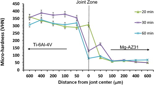
For Mg–AZ31/Ni–Cu/Ti–6Al–4V configuration, as the bonding time increased from 20 to 30 min the microhardness profile increased inside Ti–6Al–4V, then decreased when the bonding time increased from 30 to 60 min (). The maximum value obtained at the joint centre was 308 VHN of bonds made for 20 min. The decrease in microhardness profile resulted at 60 min bonding time can be attributed to the continuous formation of eutectic. This observation is also consistent with the continuous increase in joint width with increasing bonding time. In comparison to the other configuration where Cu foil is next to Mg–AZ31 the microhardness profile shows different behaviour, such that the increase in bonding times did not result in an increase in microhardness values at the joint. For Mg–AZ31/Ni–Cu/Ti–6Al–4V configuration, the microhardness values tend to be similar to that of the Mg–AZ31 parent alloy value at a distance of 100 μm towards the magnesium alloy with a 50–70 VHN range.
Shear strength evaluation
The joint shear strength as function of bonding time is shown in . For Mg–AZ31/Cu–Ni/Ti–6Al–4V configuration, the maximum shear strength obtained was 27 MPa. This value was double the value obtained when bonds were made using a single Ni foil of (11 MPa).Citation23 As the bonding time increased to 20 min the shear strength value reduced to 18 MPa. However, this value was still higher than the joint strengths obtained for a single Ni foil bonded at 515°C, and 0·2–0·7 MPa. This decrease in shear strength was attributed to the change in Cu–Mg concentration before the reaction with Ni. Further increase in bonding times to 30 min resulted in an increase in the shear strength value to 23 MPa which corresponds to a 5 times increase compared to a value of 3·5 MPa obtained by using single Ni foils.Citation23 This increase was attributed to the formation of Ni–Mg eutectic at the joint centre. However, when the bonding time was increased to 60 min, a decrease in joint shear strength to a value of 13 MPa was seen for the Mg–AZ31/Cu–Ni/Ti–6Al–4V configuration. This decrease was anticipated due to the formation of hard intermetallics seen at 50 μm from the joint centre towards the Mg–AZ31. The difference in shear strength values can be attributed to changes in joint microstructure where the formation of softer phases within the liquid eutectic and the partial solidification of the joint interface will result in a decrease in the joint strength. The formation of a more homogenised microstructure is expected to reduce the difference in shear strength.
9. Joint interface shear strength as function of bonding time
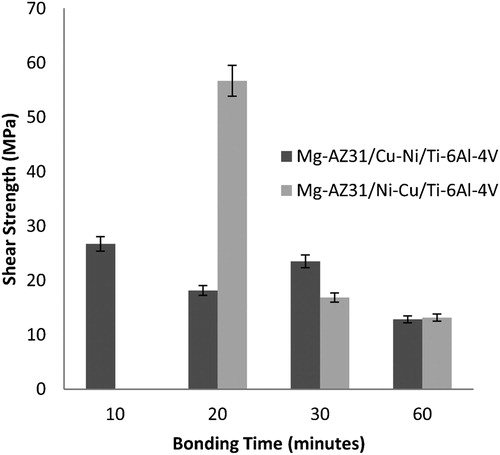
For the Mg–AZ31/Ni–Cu/Ti–6Al–4V configuration, a maximum shear strength value of 57 MPa was obtained. This value was five times the value obtained for joints made using a single Ni foil (11 MPa),Citation23 and three times the shear strength value of 18 MPa for Mg–AZ31/Cu–Ni/Ti–6Al–4V configuration. However, as the bonding time increased to 30 min, the shear strength value decreased to 17 MPa. This can be attributed to the increase in intermetallic phases formed inside the joint region, as shown in the microhardness profiles in . Further increase in bonding time to 60 min resulted in similar value seen before for Mg–AZ31/Cu–Ni/Ti–6Al–4V configuration, and a value of 13 MPa was reported. Over all, the use of two double Ni–Cu foils resulted in an increase in joint shear strength, which might be related to the smaller joint width (64 μm) compared to joint width produced (197 μm) when using the single Ni foil.Citation21–Citation23 It was also observed that the joint configuration in which Ni foil was in contact with Mg–AZ31 gave higher joint strengths than when Cu was placed in contact with Mg–AZ31.
Fractography and XRD analysis
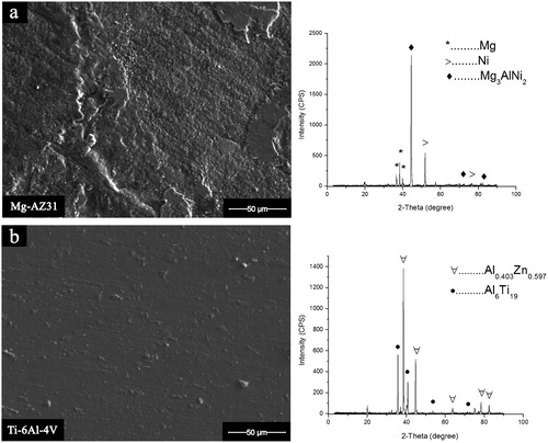
The SEM micrograph and XRD spectra achieved from the fractured surface of the bonded samples Mg–AZ31 and Ti–6Al–4V are shown in and . The complexity of the system makes it not easy to identify the formed phases and intermetallics inside the joint region where several elements are responsible in the reactions which lead to bond formation. However, the application of XRD spectra with wavelength dispersive X-ray spectroscopy and EDS makes it possible to predict and expect the formed phases even some XRD peaks could not be identified, yet it allow one to determine if the material system is behaving in a manner consistent with the theory. For Mg–AZ31/Cu–Ni/Ti–6Al–4V configuration, at a bonding time of 20 min, it resulted in brittle fracture mode and Mg3AlNi2 was observed on the Mg–AZ31 fracture surface. Furthermore, Al6Ti19 was detected on the Ti–6Al–4V fracture surface. This suggested that the fracture path was between the reaction layer L2 and Ti–6Al–4V alloy surface which also explains the lower shear strength value seen at this bonding time.
10. a Mg–AZ31 side; b Ti–6Al–4V side
Image (SEM) and XRD spectra for Mg–AZ31/Cu–Ni/Ti–6Al–4V of fractured surface for bond made 515°C, 0·35 MPa, and 20 min
11. a Mg–AZ31 side; b Ti–6Al–4V side
Image (SEM) and XRD spectra for Mg–AZ31/Ni–Cu/Ti–6Al–4V of fractured surface for bond made 515°C, 0·35 MPa, and 20 min
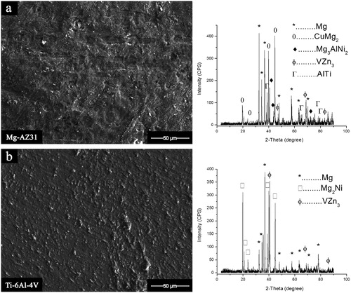
For Mg–AZ31/Ni–Cu/Ti–6Al–4V configuration, eight intermetallic compounds were detected on the fracture surface of the parent alloys for bonds made for a 20 min hold time. Only Mg and VZn3 were common on the Ti and Mg alloy fractured surfaces. The CuMg2 and Mg3AlNi2 were detected on the fracture surface of the Mg–AZ31, and a brittle failure mode was observed. On the other side, the eutectic phase of Mg2Ni was detected on the Ti–6Al–4V fracture surface. These two observations suggest that the fracture path took place between the reaction layers L1 and L2.
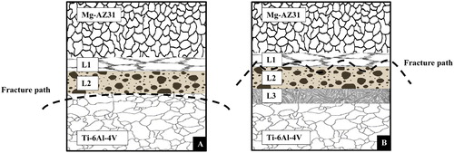
shows a schematic illustrating the fracture path observed for the Mg–AZ31/Cu–Ni/Ti–6Al–4V and Mg–AZ31/Ni–Cu/Ti–6Al–4V configurations for bonds made at 515°C for 20 min. It was observed that the fracture took different paths for each configuration at the same bonding time and bonding temperature of 20 min and 515°C; the weakest path for Mg–AZ31/Cu–Ni/Ti–6Al–4V configuration was between L2 reaction layer and the Ti–6Al–4V alloy interface. However for Mg–AZ31/Ni–Cu/Ti–6Al–4V configuration, the fracture path fluctuated between L1 and L2 reaction layers.
12. Schematic of fracture path observed for a Mg–AZ31/Cu–Ni/Ti–6Al–4V; b Mg–AZ31/Ni–Cu/Ti–6Al–4V configurations made at 515°C, 0·35 MPa for 20 min
Conclusions
Transient liquid phase (TLP) brazing of Mg–AZ31 and Ti–6Al–4V was carried out using sandwich copper and nickel foils (20 μm each) as eutectic forming interlayers. Two interlayer configurations were used; Mg–AZ31/Cu–Ni/Ti–6Al–4V and Mg–AZ31/Ni–Cu/Ti–6Al–4V. The results showed that a minimum bonding time of 10 min for Mg–AZ31/Cu–Ni/Ti–6Al–4V and 20 min for Mg–AZ31/Ni–Cu/Ti–6Al–4V was required to achieve a joint, and a time less than these values cause the two alloys not to bond. The observed mechanism of joint formation was in good agreement with the published literature and includes three stages; solid state diffusion, dissolution and widening of the joint, followed by isothermal solidification in case of the Mg–AZ31/Cu–Ni/Ti–6Al–4V. The formation of ϵ phase (Mg) and Mg3AlNi2 were observed at the fracture surface of the two configurations Mg–AZ31/Cu–Ni/Ti–6Al–4V and Mg–AZ31/Ni–Cu/Ti–6Al–4V. However, the formation of ρ (CuMg2) and δ (Mg2Ni) phases were observed at the fracture surface of configuration Mg–AZ31/Ni–Cu/Ti–6Al–4V. The XRD results were in good agreement with the literature for the evaluation of Cu–Mg–Ni ternary system. The maximum shear strength obtained was 57 MPa for bonds using the Mg–AZ31/Ni–Cu/Ti–6Al–4V joint configuration using the bonding conditions of 515°C, 0·35 MPa for 20 min.
Acknowledgements
The authors would like to acknowledge The German Jordanian University (GJU), and NSERC Canada for the financial support for this research.
Related Research Data
References
- Gale W. and Butts D.: ‘Overview transient liquid phase bonding’, Sci. Technol. Weld. Join., 2004, 9, 283–300.
- Sun D., Liu W. and Gu X.: ‘Transient liquid phase bonding of magnesium alloy (Mg-3Al-1Zn) using copper interlayer’, Mater. Sci. Technol., 2004, 20, 1595–1598.
- Sun D., Gu X. and Liu W.: ‘Transient liquid phase bonding of magnesium alloy (Mg-3Al-1Zn) using aluminum interlayer’, Mater. Sci. Eng. A, 2005, A391, 29–33.
- Cooke K. O., Khan T. I., and Oliver G. D.: ‘Transient liquid phase diffusion bonding Al-6061 using nano-dispersed Ni coatings’, Mater. Des., 2012, 33, 469–475.
- Wierzbicka-Miernik A., Wojewoda-Budka J., Litynska-Dobrzynska L., Kodentsov A., and Zieba P., ‘Morphology and chemical composition of Cu/Sn/Cu and Cu(5 at-%Ni)/Sn/Cu(5 at-%Ni) interconnections’, Sci. Technol. Weld. Join., 2012, 17, 32–35.
- Lee E., Quintana O., Indacochea J. E., Wojarski L., Pfeiffer J. and Tillmann W.: ‘Joining of aluminium sheets by combined solid state and TLP bonding processes’, Sci. Technol. Weld. Join., 2013, 18, 98–102.
- Cooke K., Khan T. and Oliver G.: ‘Effect of Ni-Al2O3 nanocomposite coating thickness on transient liquid phase bonding of Al 6061 MMC’, Sci. Technol. Weld. Join., 2012, 17, 22–31.
- Gurrapa I.: ‘Characterization of titanium alloy Ti-6Al-4V for chemical, marine and industrial applications’, Mater. Charact., 2003, 51, 131–139.
- Lütjering G. and Williams J. C.: ‘Titanium’; 2007, Berlin, Heidelberg, Springer.
- Friedrich H. E. and Mordike B. L.: ‘Magnesium technology metallurgy, design data, and applications’; 2006, Berlin, Heidelberg, Springer.
- Kulekci M. K.: ‘Magnesium and its alloys applications in automotive industry’, Int. J. Adv. Manuf. Technol., 2007, 39, 851–865.
- Mordike B. L. and Ebert T.: ‘Magnesium properties, applications, potential’, Mater. Sci. Eng. A, 2001, A302, 37–45.
- Elthalabawy W. and Khan T.: ‘Eutectic bonding of austenitic stainless steel 316L to magnesium alloy AZ31 using copper interlayer’, Int. J. Adv. Manuf. Technol., 2011, 55, 235–241.
- Elthalabawy W. and Khan T.: ‘Microstructural development of diffusion-brazed austenitic stainless steel to magnesium alloy using a nickel interlayer’, Mater. Charact., 2010, 61, 703–712.
- Jin Y. J. and Khan T. I.: ‘Effect of bonding time on microstructure and mechanical properties of transient liquid phase bonded magnesium AZ31 alloy’, Mater. Des., 2012, 38, 32–37.
- Rahman A. H. M. E. and Cavalli M. N.: ‘Diffusion bonding of commercially pure Ni using Cu interlayer’, Mater. Charact., 2012, 69, 90–96.
- Wang J., Li K., Li H., Li W., Li Z. and Guo L.: ‘Partial transient liquid phase bonding of carbon/carbon composites using Ti–Ni–Al2O3–Si compound as interlayer’, J. Alloys Compd, 2013, 550, 57–62.
- Kundu S. and Chatterjee S.: ‘Effect of temperature on formation of reaction products and strength properties of titanium and stainless steel joints using copper interlayer’, Mater. Sci. Technol., 2007, 23, 368–373.
- Gu X. Y., Sun D. Q., Liu L. and Duan Z. Z.: ‘Microstructure and mechanical properties of transient liquid phase bonded TiCP/AZ91D joints using copper interlayer’, J. Alloys Compd, 2009, 476, 492–499.
- Kundu S., Ghosh M., Laik A., Bhanumurthy K., Kale G. B., and Chatterjee S.: ‘Diffusion bonding of commercially pure titanium to 304 stainless steel using copper interlayer’, Mater. Sci. Eng. A, 2005, A407, 154–160.
- Atieh A. M., Elbatanouny M. and Khan T. I.: ‘Diffusion bonding of Ti-6Al-4V and Mg-AZ31 using Ni foil’, Proc. Mater. Sci. & Technol., (JASM XIV), Pittsburgh, PA, USA, October 2012, MS&T, 324–331.
- Atieh A. M. and Khan T. I.: ‘Transient liquid phase bonding of Ti-6Al-4V and Mg-AZ31 using eutectic forming interlayers’, Proc. 24th Canadian Cong. Appl. Mech. (CANCAM), Saskatoon, SK, Canada, June 2013, University of Saskatchewan, MS84–MS87.
- Atieh A. M. and Khan T. I.: ‘Effect of process parameters on semi-solid TLP bonding of Ti–6Al–4V to Mg–AZ31’, J. Mater. Sci., 2013, 48, 6737–6745.
- Zuo Y. and Chang A.: ‘Thermodynamic calculation of the Mg-Cu phase diagram’, Z. Met., 1993, 84, 662–667.
- Okamoto H.: ‘Mg-Ni (Magnesium-Nickel) Supplemental Literature Review: Section III’, J. Phase Equilib. Diffus., 2007, 28, 303–303.
- Miettinen J.: ‘Thermodynamic description of Cu-Mg-Ni and Cu-Mg-Zn systems’, CALPHAD: Comput. Coupling Phase Diagr. Thermochem., 2008, 32, 389–398.
- Miettinen J.: ‘Thermodynamic description of the Cu-Al-Ni system at the Cu-Ni side, Cu-Ni Phase Diagram’, CALPHAD: Comput. Coupling Phase Diagr. Thermochem., 2005, 29, 40–48.
- Gupta K. P.: ‘The Cu-Mg-Ni (copper-magnesium-nickel) system’, J. Phase Equilib. Diffus., 2004, 25, 471–478.
- Raghavan V.: ‘Al-Mg-Ni (aluminum-magnesium-nickel)’, J. Phase Equilib. Diffus., 2009, 30, 274–275.
- Bormann R. and Zöltzer K.: ‘Determination of the thermodynamic functions and calculation of phase diagrams for metastable phases’, Phys. Status Solidi A, 1992, 131A, 691–705.
- Turchanin M. A., Agraval P. G. and Abdulov A. R.: ‘Thermodynamic assessment of the Cu-Ti-Zr system. I. Cu-Ti system’, Powder Met. Met. Ceram., 2008, 47, 344–360.