
Abstract
The effect of Mo additions on the development of bainitic ferrite in hot rolled low carbon (0·05 wt-%C) Nb containing steel strips has been studied. The steel strips were fabricated by a combined process of controlled rolling and accelerated cooling. Microstructural characterisation and mechanical testing for the corresponding strips were investigated. The results indicated that a small amount of Mo addition (0·1–0·3 wt-%) causes the production of a high volume fraction of bainite, which undergoes significant secondary hardening after tempering treatment at 600°C for 1 h. It is noticeable that the secondary hardening effect provides an additional way to significantly increase the strength of low carbon Nb–Mo containing bainitic steels.
Introduction
The structure of steel can be influenced by processing and alloying in many different ways. The conventional microstructure of Nb containing high strength low alloy steels is a mixture of allotriomorphic ferrite and pearlite. Through the suitable addition of microalloying elements and an accelerated cooling process, it is possible to produce a high quantity of bainitic structures in low carbon steels. The development of low carbon bainitic steels originates from the idea that an extremely low carbon concentration can reduce or eliminate the interplate cementite in the bainitic ferrite matrix, thereby further improving the steel’s toughness.Citation1 With higher amounts of bainite, higher strengths can be achieved due to the fine size of bainitic ferrite subunit platelets and their high dislocation density. Ideally, a low carbon bainitic structure offers an excellent combination of toughness, strength and weldability.
The typical microstructure of low carbon bainitic steels is a fine substructured bainitic ferrite matrix with certain amounts of uniformly distributed carbon rich second phases.Citation2–Citation7 These second phases, located among the sheaves of bainitic ferrite, consist basically of martensite/austenite constituents. As a result of the low angle of the boundaries of bainitic ferrite subunits within the sheaf structure, little or no evidence of ferrite boundaries can be detected by optical microscopy. The first investigation of low carbon bainite dates back to 1956, when Habraken and Economopolus examined the optical microstructure of continuously cooled low carbon steels.Citation8 They revealed that the microstructure consisted of coarse plates with tiny islands of retained austenite and martensite, and that the coarse plate appeared to have an almost entirely granular aspect, a structure they termed granular bainite.Citation8 Since then, the term has become popular in steel research, as many conclusions from microstructural characterisation have been generated from observations with optical microscopy. The purposes of the present study are to gain further insight into the details of the low carbon bainite substructure and to evaluate its mechanical properties. The synergistic effect of Nb–Mo addition on the formation of low carbon bainite is also assessed.
In the steel industry, the final stage of making strips is coiling. During the coiling process, which is typically performed between 450 and 650°C, the strips are tempered. In the present work, the tempering behaviour of low carbon bainitic steels was investigated in order to exploit the potential for secondary hardening. Secondary hardening has been known to occur in tempered martensite in steels containing strong carbide forming elements such as Mo, Nb, V and Cr. In the early stage, tempering martensite decreases the hardness as cementite particles precipitate in solid solution, but the hardness begins to increase as these alloy carbides form. Secondary hardening involves the replacement of metastable cementite with the alloy carbides.Citation9 The formation of these alloy carbides requires the long range diffusion of the corresponding substitutional atoms, but their precipitation is rather sluggish. Coarsening of alloy carbides eventually leads to a decrease in hardness at long tempering times such that a secondary hardening peak occurs in the curve for hardness versus tempering time.
It is generally recognised that secondary hardening reactions in alloy steels with a bainitic microstructure are slower than in alloy steels with martensite because the coarser cementite particles take a longer time to dissolve in the tempered bainite before alloy carbides form.Citation9 However, in the present work, the experimental steels were prepared with an extremely low carbon concentration (0·05 wt-%C) in order to reduce or eliminate the interplate cementite in the bainitic ferrite matrix so as to avoid interference from the cementite during tempering. In the present study, the focus was on tempered bainite, which was studied through high resolution TEM (HR-TEM) examination and Vickers hardness measurements for the purpose of investigating secondary hardening in low carbon bainite.
Experimental
The main aim of the present work was to investigate the effect of adding Mo on the development of the microstructure in hot rolled low carbon Nb containing bainitic steels. The investigation involved three different steels. These three experimental steels were prepared by vacuum melting and then cast into 100 kg slabs with a thickness of 160 mm. The chemical compositions of the steels are listed in . The three steels had the same base composition, 0·05C–1·7Mn–0·08Nb (wt-%). One had no Mo addition (reference steel), and the other two contained 0·1 and 0·3 wt-%Mo respectively. Reference steel was designated as steel Nb, and the 0·1 and 0·3 wt-%Mo containing steels as steel Nb–Mo and steel Nb–3Mo respectively. The steels were alloyed with 0·016 wt-%Ti in order to fix nitrogen by producing stable TN. It is assumed that the titanium concentration (wt-%) should be ∼3·4 times that of nitrogen in order to fix nitrogen.Citation1
Table 1. Compositions of three hot rolled strips/wt-%
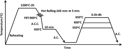
The steel strips were fabricated from the slabs by a combined process of controlled rolling and accelerated cooling; a schematic diagram of the whole process is presented in . The slabs were heated at 1200°C for 2 h before rough rolling, which began at 1050°C. During the course of rolling, the temperatures were measured by an optical pyrometer. The rolling reduction per pass was ∼20%, and the finish rolling thickness was 5 mm. After the finish rolling at 900°C, the strips (5 mm in thickness) were treated by accelerated cooling to 450°C and held at that temperature for 10 min, after which they were finally cooled to room temperature by air cooling. The three different strips were labelled as strips Nb, Nb–Mo and Nb–3Mo accordingly. The strips were then tempered at 550, 600 and 650°C for different time periods (0·5, 1, 2, 4 and 8 h) in order to investigate the tempering of bainite.
1. Schematic diagram of thermomechanical process with tempering treatments for strips Nb, Nb–Mo and Nb–3Mo
The specimens for optical metallography (OM) and scanning electron microscopy (SEM), which were prepared from the strips, were mechanically polished and then etched in 3% nital solution. The Vickers hardness test was performed with a load of 10 g on OM samples. Transmission electron microscopy specimens were prepared by cutting discs from the strips, thinning the discs mechanically to 0·06 mm and then twin jet electropolishing them to perforation using a mixture of 5% perchloric acid, 20% glycerol and 75% ethanol at −2°C and a potential of 35 V. The specimens were examined on a Tecnai F30 field emission gun scanning transmission electron microscope equipped with an energy dispersive X-ray (EDX) spectrometer. The specimens for the Tecnai Nova 450 SEM electron backscatter diffraction (EBSD) were prepared by the same method as the TEM thin foils, but without perforation. Orientation mapping for the EBSD data was performed on an observation area (100×100 μm) of each sample with a 0·2 μm step size. Bruker-CrystAlign software was used for orientation measurement and analysis.
Results and discussion
Evolution of microstructure
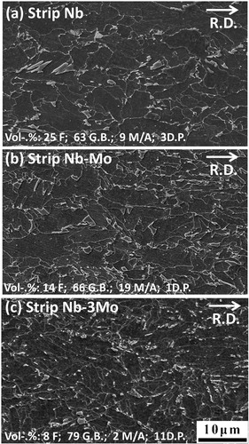
Images (SEM) of strips Nb, Nb–Mo and Nb–3Mo are presented in . They show that the second phase particles were dispersed among coarse ferrite plates, which appear to have a granular morphology (i.e. conventionally called granular bainite). Under SEM observation, a striking feature of strip Nb–3Mo () is that the prior austenite grain boundaries were approximately aligned along the rolling direction and became straight markings. This occurred because the finish rolling leaves the final austenite in an unrecrystallised, pancake shape. However, parts of the prior austenite grain boundaries become unclear because they were decorated by the fine grains of allotriomorphic ferrite, as shown in Fig. S1 in Supplementary Material 1 http://dx.doi.org/10.1179/1743284714Y.0000000536.S1. The structures of the strips were also studied in detail by TEM. Representative TEM images for allotriomorphic ferrite and granular bainite are presented in . shows that the allotriomorphic ferrite possessed an equiaxed morphology, which did not contain any subgrained structure; the strain induced Nb carbides, which first formed in prior austenite, were observed in allotriomorphic ferrite grains. displays the typical substructural feature of granular bainite, clearly showing that the coarse ferrite plates, referred to as granular bainite, did not really exist. In fact, the coarse plates of granular bainite were composed of parallel fine elongated platelets with a thickness of ∼0·5 μm. The TEM result is very similar to those reported elsewhere.Citation2–Citation7 The fine elongated platelet shape was directly related to the displacive transformation. The parallel fine elongated platelets had a similar orientation and formed a sheaf morphology, which was not different from that of ordinary bainite. The peculiar feature of granular bainite is the lack of the austenite thin films and carbides within the bainitic ferrite because of the low carbon content. The formation of second phases resulted from the carbon that was partitioned from bainitic ferrite, stabilising the residual austenite, so that the final microstructure contained some martensite/austenite constituents. The microstructures of second phases depend on the degree of carbon enrichment. It is absolutely vital to know the quantitative volume fractions of granular bainite, martensite/austenite constituents, etc., so that the structure–property relationship can be evaluated. Quantitative metallography using SEM-EBSD was utilised in the present work; the related analysis is presented later in this section. The volume percentages (vol.-%) of the different phases in the three hot rolled strips are listed in .
2. Scanning electron micrographs showing as received microstructures in a strip Nb, b strip Nb–Mo and c strip Nb–3Mo (R.D., rolling direction)
3. Typical TEM images showing a ferrite with interior strain induced Nb carbides and b granular bainite in strip Nb–3Mo
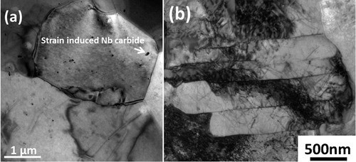
Table 2. Volume percentage of phases in three hot rolled strips*
In the present work, TEM was used to observe the morphology of granular bainite and determine subunit ferrite platelet boundaries; however, it was problematic to assess the volume fraction of granular bainite in the steel strips due to the limited size of the TEM observation area. With the traditional SEM, the substructure of granular bainite could not be discerned. To overcome this problem, the SEM-EBSD technique was employed and the density distribution of the misorientation angle between adjacent ferrite regions (by a step size of 0·2 μm) in a given granular shaped ferrite was investigated. The orientation relationship between a pair of crystals with identical structure, the crystallographic bases of which are defined from a common origin, can be presented using a rotation matrix. From the rotation matrix, a corresponding axis/angle pair can be derived. This infers that, if one of the crystals is rigidly rotated about the specified axis that passes through the original, through a right handed angle of rotation, its orientation coincides with that of the other. For each pair of ferrite [body centred cubic (bcc)] crystals, there are 24 crystallographically equivalent descriptions in terms of axis angle pairs or rotation matrices.Citation10 In the present work for SEM-EBSD, the equivalent axis angle pair with the smallest angle of rotation was chosen for each pair of adjacent ferrite regions in order to interpret the data clearly.
The orientation micrograph in was obtained from EBSD imaging for the granular bainite in strip Nb; the distribution of colours in the overall microstructure depends on the crystal orientation. The image is associated with the contrasts in brightness for corresponding Kikuchi patterns generated from all points on the analysed sample. The image quality of granular bainite is a matter of concern because the high dislocation densities in bainite could influence the quality of Kikuchi patterns and cause misleading representations of the misorientation angle. In order to make clear this issue, the regions marked with A and B were examined. The corresponding Kikuchi patterns for points A and B in are clearly shown with an image quality of >0·6, which indicates that the dislocation density in granular bainite did not have a serious effect on the EBSD imaging in the present work. In the present study, the detection of the misorientation angle is significant for microstructural characterisation. The misorientation angle profile versus the scanned distance (as shown in ) was obtained by CrystAlign software from Bruker Corp.; it shows the accumulated point to origin orientation differences. It indicates that point A (A matrix) has a relative 2·99° misorientation angle to point B (B matrix). The Euler angles of points A and B were detected to be (324° 21° 12°) and (320° 19° 14°) separately, relative to the coordination of the sample (S). They can be derived to the following rotation matrixes relative to the coordination of the sample.
4. a electron backscatter diffraction map of strip Nb, b gradient of misorientation from point A to B in purple region, c gradient of misorientation from point C to point D in green region and d, e corresponding simulated Kikuchi patterns at points A and B in a
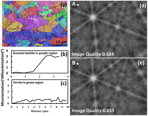
The detailed notation of coordinate transformation matrix can be referred to the related work example.Citation10 From coordinate transformation matrix (A J B), 24 equivalent axis angle pairs can be obtained as shown in . The axis angle pair with the smallest angle of rotation, [0·9971–0·2312 0·7082]/2·99°, is listed in the first row in . It is noted that the smallest angle has been chosen for the general interpretation on the misorientation of the adjacent structures in the EBSD image. In , the coarse plate region (marked by A–B) is identified as granular bainite because a significant misorientation gradient (∼3°/4 μm) exists within the coarse plate region; the accumulated point to origin orientation differences is shown in . The shape deformation accompanying the transformation of bainite induces plastic strain in the adjacent austenite and causes minor rotation of the orientation during the subsequent formation of bainite subunits.Citation11,Citation12 As a result, the orientation gradient occurs across the individual granular shape area of bainite. The observed orientation gradient is consistent with a previous investigationCitation13 (an orientation gradient of 3–6°/10 μm). On the other hand, the region marked by C–D in is recognised as allotriomorphic ferrite structure because the detected orientation gradient is very small, ∼1°/10 μm, and can be negligible (as shown in ). EBSD measurements have been carried out to provide information regarding the density distribution for the misorientation of the boundaries in the microstructure for strips Nb, Nb–Mo and Nb–3Mo. The density distributions of grain boundary misorientation angle for these strips (with the scanned area 100 μm×100 μm each sample) are displayed in ; it is clearly demonstrated that two peaks (with highest frequency) are located around 0–10° and large misorientations of between 50 and 60°. The result is consistent with that reported in the previous work for a high quantity of bainitic structure.Citation14 It is expected that the misorientations between Kurdjumov–Sachs crystallographic variants within a given austenite grain can be large (50–60°).
5. Misorientation angle profiles for strips Nb, Nb-Mo and Nb-3Mo
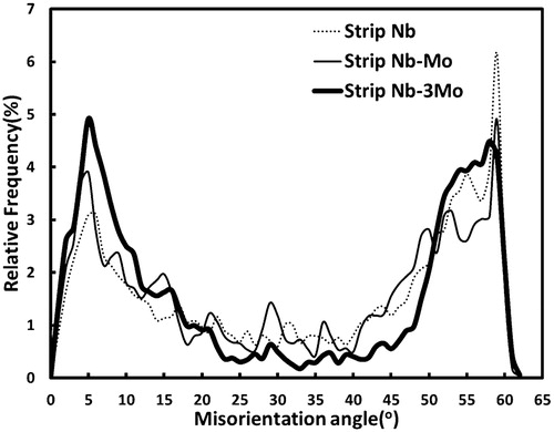
Table 3. List of 24 axis angle pairs for adjacent grains A and B
In the present work, the volume percentages of allotriomorphic ferrite and granular bainite were measured from EBSD images of all strips as shown in Supplementary Material 2 http://dx.doi.org/10.1179/1743284714Y.0000000536.S2, and the volume percentages of martensite/austenite phases and degenerated pearlite in second phases were estimated from SEM images. The combined data from SEM and EBSD images were used to estimate the volume percentages of phases, and the results are shown in . The result shows that the addition of 0·1 wt-%Mo obviously retarded the formation of allotriomorphic ferrite but slightly promoted the formation of granular bainite. It is also indicated that the addition of 0·3 wt-%Mo greatly suppressed the formation of allotriomorphic ferrite but significantly promoted the transformation of granular bainite and refined the whole microstructure.
As to the second phases in the strips, the formation of second phases (martensite/austenite constituents) resulted from the carbon, which was partitioned from the bainitic ferrite and allotriomorphic ferrite into the residual austenite, bringing about that the final microstructure contained both retained austenite and some high carbon martensite. However, in the Nb–3Mo strip, most of the second phases were resolved as the degenerated pearlite. The possible reason can be explained as follows. The size of the second phase in Nb–3Mo strip was refined by promoting the formation of granular bainite (as shown in ). The carbon concentration in the untransformed austenite increased with the decrease in its size after the transformation of allotriomorphic ferrite and bainite. A previous studyCitation15 noted that the thermal stability of residual austenite was affected by its size, and that the refined form, with a higher carbon concentration, had the high probability to induce cementite precipitation. It is suggested that the carbon atoms, which are rejected from bainite and allotriomorphic ferrite into fine residual austenite, accumulate to exceed the extrapolated Acm in the Fe–C diagram (as shown in Supplementary Fig. S3 in Supplementary Material 3 http://dx.doi.org/10.1179/1743284714Y.0000000536.S3), and trigger pearlitic reaction, forming the degenerated pearlite structure in the second phases.
Secondary hardening of granular bainite
In a related study of low carbon high Nb bearing steels,Citation16 it was found that dense dislocation lines in acicular ferrite caused significant secondary hardening after aging. Related researchCitation17,Citation18 has confirmed that the dislocation line is the most advantageous nucleation site for heterogeneous precipitation of Nb carbides in a bcc matrix. In the present work, extensive TEM investigation has been performed. A representative TEM in presents that the same variant of nanometre sized Nb carbides precipitated on the dislocation line in the region with a dashed rectangle in . Moiré fringes of the carbides as presented in can be seen around the given dislocation line; the corresponding fast Fourier transform (FFT) image as presented in shows that the carbides contained Baker–Nutting orientation relationship with a bainitic matrix. This result strongly indicates that the dislocation lines are advantageous nucleation sites for the nanometre sized Nb carbides at the bainitic matrix during tempering. Therefore, it is reasonable to conclude that the dislocation density is profoundly connected with the secondary hardening during the tempering of bainite. In measurement of dislocation density, a detailed procedure in the previous workCitation19 was adopted. Ten TEM images taken from three to four foils under magnifications of 60,000–100,000 were utilised to determine the average dislocation density for the granular bainite in each specimen. The dislocation densities of the granular bainite in strips Nb, Nb–Mo and Nb–3Mo have been estimated to be (5·3±1·2)×1014 m−2, (5·4±0·9)×1014 m−2 and (5·3±0·9)×1014 m−2 respectively (as presented in ). The high dislocation density in granular bainite should be associated with a significant secondary hardening effect during tempering treatment.
6. a substructure of tempered granular bainite in strips Nb with tempering at 600°C for 1 h, b distribution of nanometre sized carbides located at given dislocation lines in enlarged region of a with dashed white frame, c Moiré fringes of nanometre sized carbides, indicated by arrows in enlarged region of b with dashed white frame and d corresponding FFT image of carbides and bainitic matrix in c
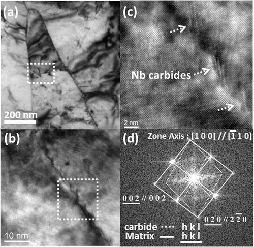
Table 4. Dislocation density of granular bainite after tempering at 600°C for different time intervals
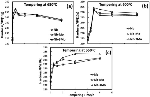
The secondary hardening effect of granular bainite can be estimated from the change in hardness. Vickers hardness measurement of the granular bainite was performed under a load of 10 g to indent only the granular bainite. Each data point of Vickers hardness (with a standard deviation of about 5–8 HV) was obtained from 30 measurements on granular bainite. As shown in , the hardness of the granular bainite in all strips rose to a maximum value (253 HV) at 650°C after 30 min and slightly decreased to 243 HV after 8 h tempering. In contrast, with tempering treatments at 550°C, the hardness increased sluggishly and did not achieve a value higher than 240 HV for all strips even after 8 h tempering. With a tempering treatment at 600°C for 1 h, the peak hardness reached 255 HV, the same as the maximum value for the tempering at 650°C for 30 min, but this value could maintain in the former case for 8 h tempering (as shown in ). Comparing all tempering treatments, a temperature of 600°C can ensure remarkable secondary hardening of the granular bainite and maintain the hardening effect for a long time. However, the additions of 0·1 and 0·3 wt-%Mo did not bring about a significant improvement of the secondary hardening effect of granular bainite for strips Nb–Mo and Nb–3Mo during 600°C tempering, as compared to that for strip Nb. In order to elucidate this phenomenon, the evolution of alloy carbides and dislocation structures in bainite during tempering need to be further investigated.
7. Hardness of granular bainite versus tempering time at a 650°C, b 600°C and c 550°C
As the secondary hardening is associated with the alloy carbide formation, it is important to reveal the details of the evolution of the nanometre sized carbides in low carbon bainite during the course of tempering. Imaging by HR-TEM with corresponding FFT diffractograms provides a unique way to investigate the orientation of nanosized carbide/ferrite.Citation20 In the present work, it was confirmed that during tempering, extremely tiny nanosized carbides formed, and these carbides satisfied the B–N orientation relationship with the bainitic ferrite matrix, and
. In the habit plane of carbides on
, the lattice mismatch was extremely small:
, whereas perpendicular to the habit plane, the lattice mismatch was relatively large:
. Such lattice mismatches favour the formation of thin platelets. It is presumable that carbides nucleated as disc particles to maintain the minimum interface energy with the ferrite matrix in the early stage, and then it grew rapidly in the best matched direction as plate-like forms during tempering, as shown in . When zone axis
was chosen for HR-TEM observation, the habit plane
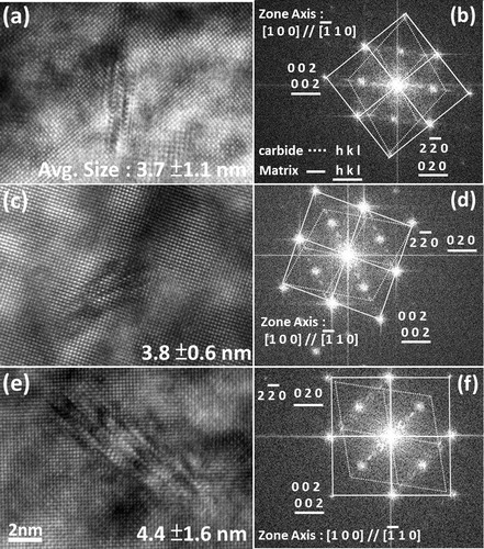
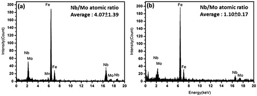
presented an edge on configuration to the incident beam direction, as shown in . The effect of Mo addition on the size of Nb carbides can be assessed by measuring the variations in the length of carbides with tempering. In addition, the degree of incorporated Mo atoms in Nb carbides can be simultaneously evaluated from the average Mo/Nb atomic ratio obtained from the nanoprobe EDX spectroscopy. Each data point of the average length of carbides and their Nb/Mo atomic ratio were respectively obtained from 50 measurements of nanometre sized carbides for each sample condition. For the samples tempered at 600°C for 1 h, the average lengths of carbides in strips Nb, Nb–Mo and Nb–3Mo were 3·7±1·1, 3·8±0·6 and 4·4±1·6 nm respectively (). The ultrafine nanometre sized carbides in tempered bainite are assured a vital source of secondary hardening for all the strips during tempering in comparison to rather coarse strain induced Nb carbides (57 nm in average size) formed in prior austenite. The spectrum in shows EDX data of (NbxMo1−x) carbides that precipitated at bainitic matrix in strips Nb–Mo and Nb–3Mo after tempering at 600°C for 1 h. The result indicates that the Nb/Mo atomic ratio in carbides is revealed to be 4·1 in strip Nb–Mo (with an original level of 0·1 wt-%Mo), which obviously decreased to 1·1 in strip Nb–3Mo (with an original level of 0·3 wt-%Mo). Although Mo becomes a more effective carbide forming element in (NbxMo1−x)C carbides with increasing Mo addition, which is consistent with thermodynamic calculations in previous research,Citation21 it has no significant effect on the thermal stability (i.e. size) of carbides in the tempered bainite.
8. Images (HR-TEM) illustrating Moiré fringes of nanometre sized carbides at bainitic matrix in a strip Nb, c strip Nb–Mo and e strip Nb–3Mo and b, d, f corresponding FFT images for strips tempered at 600°C for 1 h
9. Energy dispersive X-ray spectrum of (NbxMo1−x) carbides precipitated at bainitic matrix, being individually examined at a strip Nb–Mo and b strip Nb–3Mo after tempering at 600°C for 1 h
The data for the measured dislocation densities of granular bainite in the strips before and after tempering are presented in . Before tempering, the dislocation densities of granular bainite in strips Nb, Nb–Mo and Nb–3Mo were (5·3±1·2)×1014 m−2, (5·4±0·9)×1014 m−2 and (5·3±0·9)×1014 m−2 respectively; for tempering at 600°C for 1 h, the dislocation densities were (4·6±0·8)×1014 m−2, (4·8±1·2)×1014 m−2 and (5·1±0·8)×1014 m−2; for tempering at 600°C for 8 h, the dislocation densities were (3·9±1·3)×1014 m−2, (3·8±1·2)×1014 m−2 and (4·2±1·1)×1014 m−2. The decrease in the dislocation density for granular bainite in all strips after tempering at 600°C for 1 and 8 h is extremely small, less than the standard deviation, which indicates that the dislocation density does not change significantly during tempering at 600°C. It is revealed that the nanometre sized carbides at tempered granular bainite can effectively suppress the recovery of dislocation during tempering. In the present work, the addition of Nb (0·08 wt-%) provided an advantageous effect to maintain the dislocation density in tempered granular bainite by producing nanometre sized Nb carbides, whereas the addition of Mo had no additional beneficial effect on the thermal stability of nanometre sized Nb carbides.
The secondary hardening usually occurs during tempering of martensite.Citation22 In the initial stage of tempering, high supersaturated carbon atoms precipitated as cementite particles in tempered martensite. The dislocation density of martensite was extremely reduced during tempering. The strength of tempered martensite fell sharply with the precipitation of cementite and the decrease in dislocation density. When the transition of alloy carbides occurred at tempered martensite, there was an accompanied effect, i.e. secondary hardening. In order to obtain strength higher than that of original martensite, it usually needs a considerable addition of alloy to achieve the extra-high strength performance due to tempering. In contrast, in the present work, no precipitated cementite particle and no recovered dislocation structure occurred in the tempered granular bainite. Thereby, the strength of the low carbon Nb containing bainitic strips could maintain during the early stage of tempering. After a short period holding for tempering, the nanometre sized Nb carbides directly precipitated in the granular bainite matrix (supersaturated with a level of ∼0·04 wt-%Nb); the nanometre sized Nb carbides not only provided significant precipitation strengthening but also stabilised the dislocation structure during tempering, achieving an increased strength after tempering treatment. In terms of secondary hardening effect, Nb containing low carbon bainitic strips are advantageous because the strips are strengthened without loss of the original strength during tempering. However, from SEM-EBSD microstructure characterisation (as shown in ), it indicates that the strip without Mo addition (strip Nb) did not contain a high quantity of granular bainite.
In the present work, the mechanical properties for the strips investigated have been obtained from tensile tests (as presented in and ). It has been found that after tempering at 600°C for 1 h, the mechanical properties for all the strips could be further improved. For the strip with the addition of 0·3 wt-%Mo (strip Nb–3Mo), its tensile strength increased from 679 to 718 MPa: the increment was 39 MPa. In the strip without Mo addition (strip Nb), the increment in tensile strength was 22 MPa, from 630 to 652 MPa. The results are consistent with the quantitative metallography data from SEM-EBSD and provide a strong evidence to suggest that the addition of 0·3 wt-%Mo (strip Nb–3Mo) had the advantage of producing a high volume fraction of granular bainite, which gained a significant benefit from precipitation hardening after tempering.
Table 5. Yield/tensile strength (MPa) of as rolled strips after tempering at 600°C for different time intervals
Table 6. Elongation (%) of as rolled strips after tempering at 600°C for different time intervals
Conclusions
In the present work, three Nb containing low carbon steel strips with different Mo contents (0, 0·1 and 0·3 wt-%) were produced in a controlled rolling and accelerated cooling process. The findings can be summarised as follows.
| 1. | All the strips contained large amounts of granular bainite. The substructure of granular bainite has been revealed by TEM; granular bainite is composed of parallel fine elongated platelets with a thickness of ∼0·5 μm. The parallel fine elongated ferrite platelets have a similar orientation and form a sheaf morphology, which is no different from that of ordinary bainite. | ||||
| 2. | To obtain quantitative metallography data of the steel strips, SEM-EBSD has been utilised. The results clearly indicate that the addition of Mo promotes the formation of granular bainite. | ||||
| 3. | The strip with 0·3 wt-%Mo addition has the advantage of producing a high volume fraction of granular bainite, which gains significant benefits from secondary hardening. | ||||
Acknowledgements
The present work was carried out with financial support from Companhia Brasileira de Metalurgia e Mineração (CBMM) Corporation. The authors also thank China Steel Corporation for providing the alloy steel strips.
Notes
This paper is part of a special issue on Adventures in the Physical Metallurgy of Steels
Related Research Data
References
- Bhadeshia HKDH: ‘Production and metallurgy of advanced bainitic steels’, in ‘Steel technology international’, (ed. Scholes P H), 289–294; 1989, London, Sterling Publication.
- Wang SC and Yang JR: ‘Effect of chemical composition, rolling and cooling conditions on the amount of martensite/austenite (M/A) constituent formation in low carbon bainitic steels’, Mater. Sci. Eng. A, 1992, A154, 43–49.
- Wang SC, Hsieh RI and Yang JR: ‘Effect of rolling processes on the microstructure and mechanical properties of ultralow carbon bainitic steels’, Mater. Sci. Eng. A, 1992, A157, 29–36.
- Yang JR, Huang CY and Wang SC: ‘The development of ultra-low-carbon bainitic steels’, Mater. Des., 1992, 13, 335–338.
- Huang CY, Yang JR and Wang SC: ‘Effect of compressive deformation on the transformation behavior of an ultra-low-carbon bainitic steel’, Mater. Trans. JIM, 1993, 34, 658–668.
- Yang JR, Huang CY, Huang CS and Chiou CS: ‘The influence of plastic deformation and cooling rates on the microstructural constituents of an ultra-low carbon bainitic steel’, ISIJ Int., 1995, 35, 1013–1019.
- Chiou CS, Yang JR and Huang CY: ‘The effect of prior compressive deformation of austenite on toughness property in an ultra-low carbon bainitic steel’, Mater. Chem. Phys., 2001, 69, 113–124.
- Habraken LJ and Economopolus M: ‘Bainitic microstructures in low-carbon alloy steels and their mechanical properties’, in ‘Transformation and hardenability in steels’, 69; 1967, Ann Arbor, MI, Climax Molybdenum.
- Bhadeshia HKDH: ‘Bainite in steels’, 2nd edn, Vol. 1, 91–98; 2001, London, Iom Communications.
- Bhadeshia HKDH: ‘Worked examples in the geometry of crystals’; 1987, London, Institute of Metals.
- Bhadeshia HKDH: ‘Development in martensitic and bainitic steels: role of the shape deformation’, Mater. Sci. Eng. A, 2004, A378, 34–39.
- Pak JH, Bhadeshia HKDH and Karlsson L: ‘Mechanism of misorientation development within coalesced martensite’, Mater. Sci. Technol., 2012, 28, 918–924.
- Keeham E, Karlsson L, Bhadeshia HKDH and Thuvander M: ‘Electron backerscattering diffraction study of coalesced bainite in high strength steel weld metals’, Mater. Sci. Technol., 2008, 24, 1183–1189.
- Zhu KY, Bouaziz O, Oberbilling C and Huang MX: ‘An approach to define the effective lath size controlling yield strength of bainite’, Mater. Sci. Eng. A, 2010, A527, 6614–6619.
- Hulme-Smith CN, Lonardelli I, Peet MJ, Dippel AC, Bhadeshia HKDH: ‘Enhanced thermal stability in nanostructured bainitic steel’, Scr. Mater., 2013, 69, 191–194.
- Kestenbach H.-J: ‘Dispersion hardening by niobium crbonitride precipitation in ferrite’, Mater. Sci. Technol., 1997, 13, 731–739.
- Perrard F, Deschamps A and Maugis P: ‘Modelling the precipitation of NbC on dislocation in α-Fe’, Acta Metall., 2007, 55, 1255–1266.
- Perrard F, Donnadieu P, Deschamps A and Barges P: ‘TEM study of NbC heterogeneous precipitation in ferrite’, Philos. Mag., 2006, 27, 4271–4284.
- Yang JR and Bhadeshia HKDH: ‘The dislocation density of acicular ferrite in steel welds’, Weld. J., 1990, 69, 305–307.
- Yen HW, Chen CY, Wang TY, Huang CY and Yang JR: ‘Orientation relationship transition of nanometer sized interphase precipitated TiC carbides in Ti bearing steel’, Mater. Sci. Technol., 2010, 26, 421–430.
- Enloe CM, Findley KO, Parish CM, Miller MK, De Cooman BC and Speer JG: ‘Compositional evolution of microalloy carbonitrides in a Mo-bearing microalloyed steel’, Scr. Mater., 2013, 68, 55–58.
- Irvine KJ and Pickering FB: ‘The tempering characteristics of low-carbon low-alloy steels’, J. Iron Steel Inst., 1960, 194, 137–153.