
Abstract
Nitriding of Fe–2 at-%Mn alloy at 650°C employing a nitriding potential of 0·05 atm− 1/2 resulted in a highly complex microstructural development as a function of depth below the specimen surface: a surface adjacent layer exhibiting an austenite–martensite duplex microstructure, followed by an intermediate region showing a ferrite–austenite duplex microstructure, and at even larger depths a region where an austenite layer covers the grain boundaries of the ferrite matrix grains. Development of this complex microstructure is attributed to the strong austenite stabilising effects of Mn and N. This work demonstrates the power of a relatively simple nitriding treatment to realise a highly complex microstructure known to be associated with strongly enhanced mechanical properties.
Introduction
Enhancement of surface properties of engineering components by thermochemical surface treatments is common practice in industry.Citation1,Citation2 Gaseous nitriding likely is the most widely employed thermochemical surface treatment by which tremendous improvement of the wear, fatigue and/or corrosion resistances of steel components can be realised.Citation1,Citation3 Prediction and optimisation of the developing microstructures, and thus the resulting properties, of steel components upon nitriding require fundamental knowledge on (i) the interaction of inwardly diffusing interstitial nitrogen and the substitutionally dissolved alloying elements of the steel substrate and (ii) the effect of dissolved alloying elements and/or the already developed alloying element nitride particles in the ferrite matrix on the nucleation and growth of iron nitrides and iron–nitrogen austenite.
Fundamental nitriding studies have been carried out on relatively simple model binary and ternary iron based ferritic alloys, which led to the understanding of the basics of the thermodynamics and kinetics of the development of alloying element nitrides in ferrite.Citation3–Citation8 In addition, the influence of alloying elements on the developing iron nitride layers on ferritic steel substrates has been investigated extensively.Citation9–Citation12 The growth of iron–nitrogen (expanded) austenite layers on austenitic steel substrates has been studied.Citation1,Citation13–Citation16 However, the role of alloying elements in the steel matrix as potentially influencing the resulting nitrided microstructure, in a dramatic way, by a change of the crystal structure of the nitrided matrix, has not received distinct attention until now.
It will be shown in the present paper that the alloying element Mn, dissolved in the originally ferritic matrix, upon nitriding can give rise to the development of austenite–ferrite and austenite–martensite duplex microstructures. Such duplex microstructures are known to exhibit a desirable combination of properties.Citation17–Citation19 An Fe–2 at-%Mn alloy was chosen as model system, also in view of the usage of Mn as an austenite stabiliser in many commercial steels. Controlled gaseous nitriding experiments, i.e. at fixed chemical potential of nitrogen, were carried out. The resulting microstructures were characterised by light microscopy (LM), scanning electron microscopy, transmission electron microscopy, X-ray and electron backscatter diffraction (EBSD) and electron probe microanalysis (EPMA). A discussion based on interpretation of the obtained results is presented.
Experimental
Specimen preparation and nitriding
Fe–2 at-%Mn alloy was prepared from elemental Fe with a purity of 99·98 wt-%, and elemental Mn with a purity of 99·999 wt-% by melting in an inductive furnace under protective argon atmosphere. The alloy melts were cast into rectangular moulds of dimensions 80 × 12 × 13 mm3. The ingots were cut into two pieces and encapsulated in a quartz tube filled with argon gas. Such encapsulated cast pieces were annealed at 1000°C for 1 h to archive chemical homogeneity. The annealed cast pieces were then cold rolled to sheets of ∼1·0 mm thickness. From these sheets, rectangular specimens (20 mm × 15 mm) were cut. After grinding and polishing (finishing with 1 μm diamond paste) of the surfaces of the specimens, the specimens were encapsulated in a quartz tube filled with argon and recrystallised at 700°C for 1 h. Results of chemical analysis of the cast material are presented in ; metal contents were determined by inductively coupled plasma optical emission spectroscopy, light element contents (N and O) were determined by carrier gas hot extraction and the C content was determined by a combustion method.
Table 1 Composition of the cast Fe–2 at.%Mn alloy (balance Fe)
The specimens were nitrided in a laboratory scale, vertical quartz tube furnace having an inner diameter of 28 mm, equipped with a facility to suspend the specimen in the middle of the furnace and a water quenching flask, to quench the specimens after completion of the nitriding treatment. For the nitriding treatment, high purity ammonia (purity: 99·99 vol.-%) and hydrogen (purity: 99·999 vol.-%) gases were used. Before starting the nitriding treatment, the furnace was purged with nitrogen gas to remove all oxygen and other gases adsorbed at the furnace walls. The flowrates of the ammonia (25 mL min− 1) and hydrogen (475 mL min− 1) gases were set by MKS mass flow controllers to establish a nitriding potential rN of 0·05 atm− 1/2.3 The total gas flowrate of 500 mL min− 1 corresponds with a linear gas velocity of 13·5 mms− 1, at room temperature. The specimen was suspended in the uniform temperature (650°C) zone of the furnace with the help of a quartz fibre. At the applied temperature and nitriding potential surface, iron nitrides and Fe–N austenite cannot form upon nitriding pure iron.Citation20,Citation21 After completing the nitriding treatment, the specimens were quenched by breaking the quartz fibre, which caused the specimen to fall into the water filled quenching flask.
Characterisation of nitrided specimens
For metallographic investigation of the nitrided regions, cross-sectional specimens were cut, embedded, ground and polished (final step with 1 μm diamond paste). Then, the specimens were etched using 1 vol.-% nital and investigated using LM and scanning electron microscopy (SEM). For SEM, a Zeiss Leo 1530 VP microscope equipped with a field emission gun and employing an accelerating voltage of 3 kV was used.
Electron backscatter diffraction analysis was performed on the same cross-sections of the specimens used for the LM and SEM investigations with an additional final polishing step (0·05 μm oxide particle suspension). A Zeiss Leo 438 VP scanning electron microscope equipped with an EDAX TSL EBSD measurement system with the software OIM version 5 was used for the analysis (parameters employed for EBSD measurements are step size of 0·2 μm, voltage of 20 kV, current of 2·5 nA and background subtraction followed by intensity normalisation as filters for the Kikuchi patterns).
Elemental concentration–depth profiles were measured by performing EPMA employing a Cameca SX100 microprobe with an accelerating voltage of 15 kV and a current of 100 nA. The intensities of the measured characteristic X-ray emission peaks (Fe Kβ, Mn Kα and N Kα) from the specimens and corresponding intensities measured on standard specimens, pure Fe, Mn and γ'-Fe4N (for N Kα), were used to obtain the elemental contents at the measured location applying the Φ(ρz) approach.Citation22
X-ray diffraction measurements, using Co Kα radiation, were performed on the surface of the nitrided specimens employing a Phillips PANalytical X'pert multipurpose diffractometer having Bragg–Brentano geometry and a graphite monochromator in the diffracted beam. During the measurements, the specimens were rotated on a spinner around an axis perpendicular to its surface to improve the crystallite statistics. X-ray diffraction measurements were performed in the diffraction angle (2θ) range of 20–120°, with a step size of 0·02° (2θ) and with a counting time of 200 s per step.
Transmission electron microscopy (TEM) was carried out for characterisation of the nanosized nitride precipitates. To obtain electron transparent foils, nitrided specimens were ground from both sides (faces) until the desired location of the nitrided region (i.e. depth in the nitrided zone and parallel to the surface of the specimen). Then, discs of 3 mm diameter were punched out mechanically and subsequently thinned by ion milling applying the PIPS (Gatan precision ion polishing system) at an accelerating voltage of 3–4 kV, a current of 10–12 μA, an incidence angle of 8° and a milling time of 4–10 h. The TEM analysis was performed using a Philips CM 200 transmission electron microscope operated at 200 kV. Bright field (BF) images, dark field images and selected area diffraction patterns (SADPs) were recorded using a Gatan charge coupled device camera.
Results
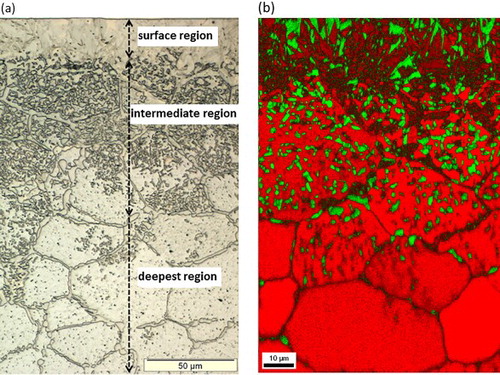
The LM images, EBSD phase maps and EPMA elemental (Mn and N) concentration–depth profiles recorded from the cross-section of a nitrided (650°C, 20 h, rN = 0·05 atm− 1/2) Fe–2 at-%Mn alloy specimen reveal the following distinct microstructures as a function of depth ():
(i) Surface adjacent region; austenite (γ)–martensite (α′) duplex microstructure: This region, appearing as a layer in the LM image (), actually consists of a mixture of strained body-centred cubic (BCC) phase ( = martensite; see caption of ) and face-centred cubic (FCC) phase, as demonstrated by the EBSD analysis (). Both phases in this region contain a nearly constant and same amount of Mn (∼1·8 at-%). The nitrogen content is ∼6·5 at-% at the surface and decreases to ∼6 at-% at the bottom of this surface adjacent layer (). As the nitrogen solubility in BCC iron can attain a value of maximally ∼0·4 at-%,Citation21 the strained BCC phase must have been FCC (Fe–N–Mn) austenite (γ) at the nitriding temperature and at the applied nitriding potential, which, upon water quenching of the specimen, from nitriding temperature to room temperature, must have transformed to BCT (Fe–N–Mn) martensite. The X-ray diffraction pattern recorded from the surface of the nitrided specimen confirmed the existence of austenite and martensite phases in the surface adjacent region (see ). Hence, the surface adjacent region consists of an austenite–martensite duplex microstructure. | |||||
(ii) Intermediate region; austenite (γ)–ferrite (α) duplex microstructure: This region shows a microstructure composed of particles of FCC crystal structure embedded in a BCC matrix (). The FCC (second phase) particles are enriched with Mn and N as compared to the surrounding BCC matrix (), which contains less Mn than the unreacted substrate. Hence, the intermediate region consists of a ferrite–austenite duplex microstructure. | |||||
(iii) Deepest nitrided region; austenite (γ) grain boundary phase: This region exhibits a layer of second phase at the grain boundaries of the ferrite matrix (), which, according to the EBSD analysis, is of FCC crystal structure () and, according to the EPMA analysis (), enriched with Mn and N. Hence, this deepest nitrided region consists of ferrite matrix grains enveloped by thin layers of austenite along the grain boundaries. | |||||
1 a light microscopy image and b EBSD phase map recorded from cross-section of Fe–2 at-%Mn alloy specimen nitrided at 650°C for 20 h using a nitriding potential of 0·05 atm− 1/2. Electron backscatter diffraction phase map reveals austenite (green), ferrite (red) and martensite (darker red regions, with plate-like morphology in surface adjacent region). Small differences in Kikuchi patterns of BCC ferrite and BCT martensite makes it difficult to distinguish between these phases. However, presence of defects in martensite results in relatively poor quality Kikuchi patterns as compared to defect poor ferrite in intermediate and deepest regions. This difference in quality of Kikuchi patterns was utilised to discern martensite and ferrite phases by overlaying fit quality of measured Kikuchi patterns on phase map. Note difference in magnification for a and b.
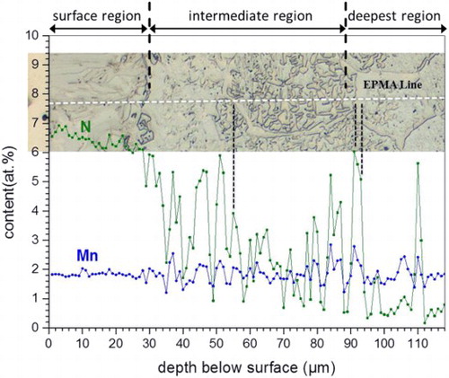
2 Elemental (Mn and N) concentration–depth profiles as determined by EPMA of Fe–2 at-%Mn alloy specimen nitrided at 650°C for 20 h using nitriding potential of 0·05 atm− 1/2. Corresponding LM image given on top shows microstructure of nitrided zone at location where EPMA measurements were made (EPMA linescan has been indicated with white dashed line). Surface adjacent region exhibits uniform Mn content, and N content, which varies from ∼6·5 at-% at surface to ∼6 at-% at bottom of surface layer. Enrichment of both Mn and N as compared to ferrite phase occurs at locations of austenite in intermediate and deepest nitrided regions
3 X-ray diffraction pattern (Co Kα) recorded from surface of Fe–2 at-%Mn alloy specimen nitrided at 650°C for 20 h using nitriding potential of 0·05 atm− 1/2. Surface adjacent region contains austenite and martensite phases
High magnification SEM images recorded from the intermediate region () and deepest nitrided regions () reveal the presence of fine platelet type and globular type second phase particles in the ferrite matrix. The TEM analysis revealed that the thin platelet type nitrides are of FCC Mn4N typeCitation23 with their broad faces parallel to {001} lattice planes of the ferrite matrix and exhibiting a Baker-NuttingCitation24 orientation relationship between the FCC type Mn4N platelets and the BCC ferrite matrix (). The TEM analysis of the globular type nitrides showed these to be of orthorhombic Mn2N0·86 typeCitation25 (; note that the orthorhombic crystal structure for this nitride can be a consequence from cooling below 0°C during ion milling for TEM foil preparation, as it has been reported that a hexagonal → orthorhombic transformation can occur upon cooling to subzero temperatureCitation25). The austenite regions in the duplex austenite+martensite and austenite+ferrite microstructures and the martensite regions in the duplex austenite+martensite microstructure do not contain Mn nitride precipitates.
4 Images (SEM) of etched cross-sections of Fe–2 at-%Mn specimen nitrided at 650°C for 20 h using nitriding potential of 0·05 atm− 1/2. a intermediate region [austenite (γ) + ferrite (α) duplex microstructure]: platelet type and globular type precipitates are present in ferrite (α) matrix. b deepest nitrided region: high density of platelet type and globular type precipitates is present in ferrite matrix grains. In both a and b, austenite is free from precipitates
![4 Images (SEM) of etched cross-sections of Fe–2 at-%Mn specimen nitrided at 650°C for 20 h using nitriding potential of 0·05 atm− 1/2. a intermediate region [austenite (γ) + ferrite (α) duplex microstructure]: platelet type and globular type precipitates are present in ferrite (α) matrix. b deepest nitrided region: high density of platelet type and globular type precipitates is present in ferrite matrix grains. In both a and b, austenite is free from precipitates](/cms/asset/f84685b3-864d-4140-9ccf-136422f7c76c/ymst_a_1098866_f0004_b.gif)
5 a TEM BF image showing the Mn nitride platelets oriented with their broad faces parallel to the 001 lattice planes of the ferrite matrix. TEM foil was prepared from ∼75 μm below the surface (i.e. intermediate region) of Fe–2 at-%Mn specimen nitrided at 650°C for 20 h using a nitriding potential of 0·05 atm− 1/2. (b) The SADP corresponding to BF image (a) showing the weak extra diffractions spots of Mn4N type platelets in addition to the intense ferrite matrix diffraction spots. (c) Calculated SADP for [001]-α-Fe zone/electron beam axis superimposed with the calculated SADP for [110]-Mn4N zone axis satisfying the Baker-Nutting (B-N) orientation relationship (OR) between the FCC Mn4N type-nitrides and the BCC ferrite matrix ((100)BCC // (001)FCC and [001]BCC // [110]FCC).
![5 a TEM BF image showing the Mn nitride platelets oriented with their broad faces parallel to the 001 lattice planes of the ferrite matrix. TEM foil was prepared from ∼75 μm below the surface (i.e. intermediate region) of Fe–2 at-%Mn specimen nitrided at 650°C for 20 h using a nitriding potential of 0·05 atm− 1/2. (b) The SADP corresponding to BF image (a) showing the weak extra diffractions spots of Mn4N type platelets in addition to the intense ferrite matrix diffraction spots. (c) Calculated SADP for [001]-α-Fe zone/electron beam axis superimposed with the calculated SADP for [110]-Mn4N zone axis satisfying the Baker-Nutting (B-N) orientation relationship (OR) between the FCC Mn4N type-nitrides and the BCC ferrite matrix ((100)BCC // (001)FCC and [001]BCC // [110]FCC).](/cms/asset/136e0bad-9ea1-4217-a0d2-8e8a3c293d44/ymst_a_1098866_f0005_b.gif)
6 a transmission electron microscopy BF image showing globular Mn nitride particle in ferrite matrix and corresponding SADP b. 132 and 241 diffraction spots of orthorhombic Mn2N0·86 could be identified.Citation25 Transmission electron microscopy foil was prepared from specimen at depth of ∼400 μm below surface (i.e. deepest nitrided region; cf. ) of Fe–2 at-%Mn specimen nitrided at 650°C for 20 h using a nitriding potential of 0·05 atm− 1/2. c dark field image formed using 132 diffraction spot of Mn2N0·86, illuminating globular Mn2N0·86 particle
Discussion
Upon nitriding a pure iron specimen at the same nitriding conditions as used in this present work for Fe–2 at-%Mn alloy (T = 650°C and rN = 0·05 atm− 1/2), only an Fe–N ferrite (solid solution) develops.Citation20,Citation26 Indeed, the employed nitriding conditions of rN = 0·05 atm− 1/2 and T = 650°C are within the α-Fe region of the Lehrer diagram,Citation20,Citation21 but they are near to the α-Fe/γ-Fe phase boundary, suggesting that the occurrence of austenite in nitrided Fe–Mn alloy can be caused by a slight shift of the α-Fe/γ-Fe phase boundary towards lower nitriding potentials and/or temperatures due to the presence of (austenite stabilising) Mn. Even a nitriding experiment performed in this present work with the same Fe–Mn alloy specimen at a much reduced nitriding potential of 0·02 atm− 1/2 at the same temperature (650°C) did already result in the formation of austenite, in particular along the ferrite grain boundaries. This finding indicates the strong promotion of austenite stability by dissolved Mn.
The interesting variation of the (duplex) microstructure that developed as a function of depth is compatible with the corresponding isothermal section of the ternary Fe–Mn–N phase diagram at 650°C and at 1 atm as predicted employing the CALPHAD approachCitation27 (). Upon introducing nitrogen at 650°C into the initially ferritic (α) Fe–2 at-%Mn alloy, the following phase sequence is expected to develop as a function of increasing nitrogen content; two phase (α + Mn6N5) → three phase (α+γ + Mn6N5) → two phase (α+γ) → single phase γ (see ; dashed line). In reverse order, this sequence shows the predicted phases as a function of depth. This prediction largely agrees with the experimental findings of this study. The occurrence of the (for these conditions) metastable Mn4N typeCitation23 and Mn2N0·86 typeCitation25 nitrides can be a consequence of small differences in the Gibbs energies of formation of these nitrides (per mole Mn; an extensive series of Mn nitrides, with some of which showing polymorphic transformation, has been reportedCitation25,Citation28–Citation32), so that kinetic reasons may favour the development of metastable nitrides.
7 Iron rich corner of isothermal section of Fe–Mn–N phase diagram at 650°C and at 1 atm.Citation27 Dashed line indicates increasing N content for Fe–Mn–N alloy and allows to predict which stable phases are expected to develop going from the unnitrided core (i.e. Fe–2at-%Mn alloy) to surface where highest N content occurs
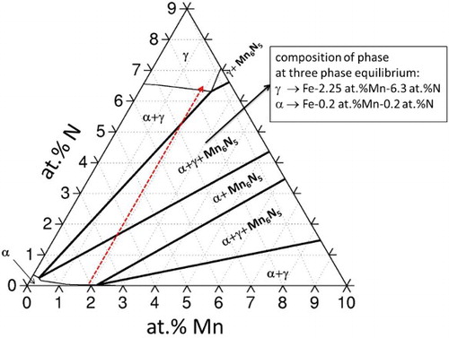
At the three phase equilibrium (α+γ + Mn6N5), the predicted Mn content of the α and γ phases is 0·2 at-% and 2·25 at-% respectively, which indicates that during nitriding, a redistribution (between ferrite and austenite) of Mn must occur to nucleate and grow the austenite in ferrite (the initial Mn content of the binary, ferritic Fe–Mn alloy is 2 at-%). Therefore, it is predicted that during the ferrite → austenite transformation upon (continued) nitriding, the Mn nitrides, which had initially developed in the ferrite matrix, dissociate into Mn and N, which get dissolved in the developing austenite, which is in agreement with the experimental observation of this study (cf. end of section 3).
Apparently, upon increasing N content, the first austenite to develop nucleates at the ferrite grain boundaries [see region (iii)]. Nucleation barriers are smaller at grain boundaries, as grain boundary energy gets released upon nucleation.Citation33 Moreover, segregation at grain boundaries of possibly Mn may promote first development of austenite there too (Mn is an austenite stabilising elementCitation34). As a next stage, and accompanied by a continuous increase in the N content, austenite develops also within the ferrite matrix grains [region (ii)], in association with dissolution of the Mn nitrides, developed before, leading to a completely austenitic region [at the nitriding temperature; region (i)].
The martensite start temperature Ms of pure iron–nitrogen austenite decreases with increasing content of dissolved N; for the amount of dissolved N larger than 8·5 at-%, the Ms temperature is beneath room temperature.Citation35–Citation37 Hence, an austenite–martensite duplex microstructure can develop, upon quenching from the nitriding temperature to room temperature, if the maximal amount of dissolved N in the austenitic surface adjacent region of a nitrided pure iron specimen is smaller than 8·5 at-%Citation38; the local amount of retained austenite then depends on the local N content that controls the local Ms temperature (note that the martensite finish temperature Mf for pure iron–nitrogen austenite is already below room temperature for dissolved N contents >2·7 at-%Citation35). The additional presence of dissolved Mn in the austenitic nitrided surface adjacent region is an additional component, but much less effective than N,Citation34 reducing the Ms temperature. Evidently, the presence of about 6–6·5 at-% dissolved N and ∼2 at-% dissolved Mn corresponds with an Ms temperature well above room temperature (cf. ), so that the duplex austenite–martensite microstructure can develop upon quenching after nitriding.
The austenite in the austenite+ferrite region (ii) apparently does not experience a martensitic transformation upon quenching of the specimen from the nitriding temperature (cf. ), although its N content is lower than that of the austenite present, at the nitriding temperature, in region (i), which by itself would cause an (even) higher Ms temperature for the austenite in region (ii) than for the austenite in region (i) (cf. above discussion). The stabilisation of austenite in region (ii) may be a consequence of an effective cooling rate naturally lower in the deeper region (ii) as compared to that experienced by the surface adjacent region (i), in combination with slow decomposition kinetics of this austenite with respect to that experienced cooling rate (note that the substitutionally dissolved Mn, as compared to the interstitially dissolved N, diffuses relatively slowly). Further, the ferrite matrix surrounding the austenite in region (ii) is strengthened by the precipitated Mn nitrides and thereby can hinder accommodation of the volume expansion that is associated with the austenite to martensite transformation.
The austenite–ferrite and austenite–martensite duplex microstructures as developed in this present work are separately known to significantly improve the mechanical properties of engineering components.Citation17,Citation18 Thereby, this work demonstrates that a relatively simple gaseous nitriding treatment allows realising such a technologically promising microstructure, which may lead to future, new applications of the nitriding process.
Conclusions
Nitriding of Fe–2 at-%Mn alloy at 650°C and at a nitriding potential of 0·05 atm− 1/2 generates a complex microstructure as a function of depth:
(i) surface region: austenite–martensite duplex microstructure | |||||
(ii) intermediate region: austenite–ferrite duplex microstructure | |||||
(iii) deepest nitrided region: ferrite matrix grains enveloped by austenite phase layer at the grain boundaries. | |||||
The sequence of phases developing as a function of depth is largely compatible with the ternary Fe–Mn–N phase diagram.
The generated duplex microstructures suggest a new field of application of the nitriding process.
Acknowledgements
We are grateful to Mr P. Kress and Mr W. Engelhardt for assistance with the nitriding experiments, to Mrs. S. Haug for performing EPMA measurements and to Professor Dr P. van Aken for providing access to the electron microscopy facilities at our institute (all with MPI-IS).
References
- E. J. Mittemeijer, M. A. J. Somers and (eds): ‘Thermochemical surface engineering of steels’, 62; 2015, Woodhead Publishing Series in Metals and Surface Engineering.
- F. Hoffmann, H. Klümper-Westkamp and (eds.): ‘Proc. European Conf. on Heat treatment 2010 - nitriding and nitrocarburising’, 2010, Aachen, AWT-Bremen.
- E. J. Mittemeijer: ‘Fundamentals of nitriding and nitrocarburizing’, in ‘ASM handbook 4A: steel heat treating fundamentals and processes’, (ed. J. Dossett et al.., 619–646; 2013, ASM International.
- S. R. Meka, E. Bischoff, S. S. Hosmani and E. J. Mittemeijer: ‘Interrelationships of defects, nitride modification and excess nitrogen in nitrided Fe-4·75 at.% Al alloy’, Int. J. Mater. Res., 2014, 105, (11), 1057–1066. doi: 10.3139/146.111127
- D. H. Jack and K. H. Jack: ‘Invited review - carbides and nitrides in steel’, Mater. Sci. Eng., 1973, 11, (1), 1–27. doi: 10.1016/0025-5416(73)90055-4
- G. Miyamoto, Y. Tomio, H. Aota, K. Oh-ishi, K. Hono and T. Furuhara: ‘Precipitation of nanosized nitrides in plasma nitrided Fe-M (M = Al, Cr, Ti, V) alloys’, Mater. Sci. Technol., 2011, 27, (4), 742–746. doi: 10.1179/1743284710Y.0000000014
- G. Miyamoto, A. Yonemoto, Y. Tanaka, T. Furuhara and T. Maki: ‘Microstructure in a plasma-nitrided Fe-18 mass% Cr alloy’, Acta Mater., 2006, 54, (18), 4771–4779. doi: 10.1016/j.actamat.2006.06.006
- M. M. Yang and A. D. Krawitz: ‘Resistometric study of Fe-V and Fe-Mo nitrided by constant activity aging’, Metall. Trans. A, 1984, 15A, (8), 1545–1554. doi: 10.1007/BF02657793
- S. R. Meka, E. Bischoff, R. E. Schacherl and E. J. Mittemeijer: ‘Unusual nucleation and growth of gamma ’ iron nitride upon nitriding Fe-4·75 at.% Al alloy’, Philos. Mag., 2012, 92, (9), 1083–1105. doi: 10.1080/14786435.2011.640295
- H. Selg, E. Bischoff, I. Bernstein, T. Woehrle, S. R. Meka, R. E. Schacherl, T. Waldenmaier and E. J. Mittemeijer: ‘Defect-dependent nitride surface layer development upon nitriding of Fe-1 at.% Mo alloy’, Philos. Mag., 2013, 93, (17), 2133–2160. doi: 10.1080/14786435.2013.765983
- S. R. Meka and E. J. Mittemeijer: ‘Abnormal nitride morphologies upon nitriding iron-based substrates’, JOM, 2013, 65, (6), 769–775. doi: 10.1007/s11837-013-0603-6
- T. Bendo, A. M. Maliska, J. J. S. Acuna, C. Binder, K. B. Demetrio and A. N. Klein: ‘Nitriding of surface Mo-enriched sintered iron: Structure and morphology of compound layer’, Surf. Coat. Technol., 2014, 258, 368–373. doi: 10.1016/j.surfcoat.2014.08.072
- T. L. Christiansen, T. S. Hummelshoj and M. A. J. Somers: ‘Expanded austenite, crystallography and residual stress’, Surf. Eng., 2010, 26, (4), 242–247. doi: 10.1179/026708410X12506870724316
- H. Dong: ‘S-phase surface engineering of Fe-Cr, Co-Cr and Ni-Cr alloys’, Int. Mater. Rev., 2010, 55, (2), 65–98. doi: 10.1179/095066009X12572530170589
- A. Martinavicius, R. Danoix, M. Drouet, C. Templier, B. Hannoyer and F. Danoix: ‘Atom probe tomography characterization of nitrogen induced decomposition in low temperature plasma nitrided 304L austenitic stainless steel’, Mater. Lett., 2015, 139, 153–156. doi: 10.1016/j.matlet.2014.09.093
- J. C. Stinville, J. Cormier, C. Templier and P. Villechaise: ‘Modeling of the lattice rotations induced by plasma nitriding of 316L polycrystalline stainless steel’, Acta Mater., 2015, 83, 10–16. doi: 10.1016/j.actamat.2014.09.052
- O. Bouaziz, S. Allain, C. P. Scott, P. Cugy and D. Barbier: ‘High manganese austenitic twinning induced plasticity steels: A review of the microstructure properties relationships’, Curr. Opin. Solid State Mater. Sci., 2011, 15, (4), 141–168. doi: 10.1016/j.cossms.2011.04.002
- J. O. Nilsson: ‘Super duplex stainless-steels’, Mater. Sci. Technol., 1992, 8, (8), 685–700. doi: 10.1179/mst.1992.8.8.685
- H. K. D. H. Bhadeshia and R. W. K. Honeycombe: ‘Steels: microstructure and properties’, 2006, Amsterdam, Butterworth-Heinemann.
- E. Lehrer: ‘Iron-hydrogen-ammoniac balance’, Z. Elektrochem., 1930, 36, 383–392.
- J. Stein, R. E. Schacherl, M. S. Jung, S. Meka, B. Rheingans and E. J. Mittemeijer: ‘Solubility of nitrogen in ferrite; the Fe-N phase diagram’, Int. J. Mater. Res., 2013, 104, (11), 1053–1065. doi: 10.3139/146.110968
- J. L. Pouchou and F. Pichoir: ‘A new model for quantitative x-ray-microanalysis .1. application to the analysis of homogeneous samples’, Rech Aerospatiale, 1984, (3), 167–192.
- G. Hagg: ‘X-radiation tests on the nitride of manganese’, Z. Phys. Chem. B, 1929, 4B, (5), 346–370.
- R. G. Baker and J. Nutting: ‘The tempering of a Cr-Mo-V-W and a Mo-V steel’ ‘Special report 64’, 1–22; 1959, London, Iron and Steel Institute.
- E. F. Nasreddine and E. F. Bertaut: ‘Crystallographic and magnetic-structure of Mn2n0·86 at low-temperatur’, Solid State Commun, 1977, 23, (3), 147–150. doi: 10.1016/0038-1098(77)90097-7
- E. J. Mittemeijer and J. T. Slycke: ‘Chemical potentials and activities of nitrogen and carbon imposed by gaseous nitriding and carburising atmospheres’, Surf. Eng., 1996, 12, (2), 152–162. doi: 10.1179/sur.1996.12.2.152
- Thermo-Calc Software TCFE7 Steels/Fe-alloys database version 7.
- J. D. Baird: ‘Precipitation of nitrides in iron-manganese-nitrogen alloys’, J. Iron. Steel Inst., 1966, 204, 1122–1130.
- P. Ferguson and K. H. Jack: ‘A lattice imaging study of nitrogen precipitation in alpha-iron and Fe-2·17 at percent-Mn’, Philos. Mag. A, 1984, 50A, (2), 221–232.
- J. F. Enrietto: ‘Solubility and precipitation of nitrides in alpha-iron containing manganese’, Trans. Metall. Soc. AIME, 1962, 224, (1), 43–48.
- M. Goune, T. Belmonte, A. Redjaimia, P. Weisbecker, J. M. Fiorani and H. Michel: ‘Thermodynamic and structural studies on nitrided Fe-1·62%Mn and Fe-0·56%V alloys’, Mater. Sci. Eng. A, 2003, A351, (1-2), 23–30. doi: 10.1016/S0921-5093(02)00277-0
- M. Goune, A. Redjaimia, T. Belmonte and H. Michel: ‘Identification and characterization of a novel Mn-N nitride formed in Fe-Mn-N alloy’, J. Appl. Crystallogr., 2003, 36, 103–108. doi: 10.1107/S0021889802020101
- E. J. Mittemeijer: ‘Fundamentals of materials science’, 2010, Berlin, Springer-Verlag.
- K. W. Andrews: ‘Empirical formulae for calculation of some transformation temperatures’, J. Iron Steel Inst., 1965, 203, 721–727.
- T. Bell: ‘Martensite transformation start temperature in iron-nitrogen alloys’, J. Iron Steel Inst., 1968, 206, 1017–1021.
- T. Bell and W. S. Owen: ‘Martensite in iron-nitrogen alloys’, J. Iron Steel Inst., 1967, 205, 428–434.
- T. Bell and W. S. Owen: ‘Thermodynamics of martensite transformation in iron-carbon and iron-nitrogen’, Trans. Metall. Soc. AIME, 1967, 239, (12), 1940–1949.
- B. Schwarz, H. Gohring, S. R. Meka, R. E. Schacherl and E. J. Mittemeijer: ‘Pore formation upon nitriding iron and iron-based alloys: the role of alloying elements and grain boundaries’, Metall. Mater. Trans. A, 2014, 45A, (13), 6173–6186. doi: 10.1007/s11661-014-2581-x