
Abstract
Prior to 1900 the railways were mainly built by manual labour. Masonry arch, timber and cast-iron bridges were constructed piecemeal. Long spans over waterways were floated out on pontoons and raised using hydraulic presses. As bridges of timber and cast iron became unsuitable they were replaced by wrought iron and later by steel or concrete. Speed of construction was vital once railways came into use demanding that works were carried out in track possessions and this influenced construction methods thenceforth. Steam breakdown cranes appeared from 1875 and were soon being used in bridge construction. As crane capacities increased bridges were erected in larger elements. The adoption of welding to replace riveting and wider use of concrete in superstructures after 1945 was assisted by the introduction of road mobile cranes whose capacities reached 1000 tons by the 1990s. ‘Rolling-in’ of spans preassembled alongside the tracks was developed to reduce possession periods. From the 1980s Transporters were introduced to install complete spans, so eliminating temporary works. Substructures beneath live tracks had been traditionally constructed in cofferdams spanned by waybeams, but from the 1960s pipe-jacking techniques were adapted to form such substructures. Piled foundations on each side of the railway have increasingly been adopted and from the 1970s integral portal frame bridges or boxes have been installed by sliding-in, with transporters, by jacking or pulling in open cut.
Introduction
Until the 1960s the British main line railways contained approximately 60,000 bridges, since reduced through line closures to around 40,000.Citation1 This paper includes the author’s own experiences in a number of examples and mainly covers underbridges which form about 60% of the total.
The history of construction methods may be categorized thus:
| • | 1825 to 1900Pre-mechanized age | ||||
| • | From 1875Railway cranes | ||||
| • | From 1950sRoad mobile cranes | ||||
| • | From 1980sRolling-in, sliding, launching, transporters | ||||
| • | From 1960sSubstructure developments | ||||
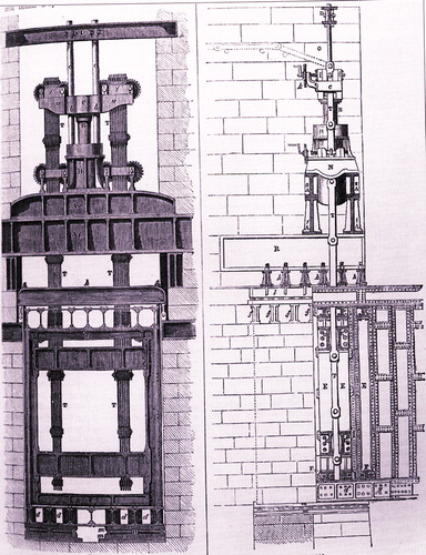
Early bridges were constructed from piecemeal components. The running rails were often fixed directly whereas ballasted track was later preferred. The legacy of shallow construction depth restricted the options when bridges were reconstructed as train weights increased.Citation2 Methods for reconstruction or for new bridges increasingly had to minimize disruption to trains, but many principles of the early techniques still apply. For example the vertical hoisting into place of the Conway and Britannia Bridges in 1849 used the same technique as in modern strand jacking. shows the lifting gear for the Conway Bridge.
FIGURE 1. Lifting gear for Conway Bridge 1849. Courtesy of the Institution of Civil Engineers
Materials and bridge types
Brick or masonry arches predominated for new-build railways and have proved to be durable, late examples of 1910 being two brick viaducts at Souldern on the Great Western and Great Central Joint Railway.Citation3 Timber bridges had beam or trussed superstructures with trestle supports often with timber pile foundations. There were thirty-four Brunel timber viaducts between Plymouth and Truro alone, all reconstructed by 1908.Citation4 In Wales a number of timber spans survive although subject to traffic restrictions. Cast-iron beams, usually supporting timber floors and longitudinal timbers, were prohibited for new construction following the failure at Inverythan in 1882Citation5 and were steadily replaced after the Norwood Junction collapse of 1891.Citation6 For spans beyond the practical limits of casting, typically 40 ft,Citation7 cast-iron beams had been built up from three lengths bolted together and reinforced by inclined wrought-iron bars as a form of prestressing. Such ‘compound cast-iron beams’ were unsafe as demonstrated by the collapse of Robert Stephenson’s Dee Bridge with spans of 98 ft in 1847, leading to an InquiryCitation8 and Board of Trade Rules.Citation9 Cast iron survived in arches and columns where stresses were mainly compressive.
The first wrought-iron railway bridge was built near Glasgow in 1841Citation10 followed by the half-through box girders at Torksey and Gainsborough of 1849, and the Conway and Britannia through-box bridges completed in 1850. The opening of Torksey Bridge had been delayed for four months due to an argument with the Board of Trade arising from the introduction of continuity on the two main spans.Citation11 Plate girders or trusses later predominated until British Railways reintroduced box girders in the 1950s. The Newark Dyke Bridge of 1850 was the first warren-truss underbridge, the compression members being of cast iron and the remainder wrought iron.Citation12 In 1859 and 1877 respectively the Board of Trade accepted the use of wrought iron and steel. The cantilever Forth Bridge in 1890 was the first major bridge to employ steel throughout, but for some years after bridges might contain a mix of wrought iron and steel. Fabrication was by riveting but welding was introduced for repair work from the 1930s.Citation13 The first all-welded bridge in the UK was the Billingham Branch portal frame overbridge in 1934Citation14 followed by a bridge at Ladbroke Grove in 1938 and seven flood washout replacements north of Berwick in 1948.Citation15 The Reading West bridge of 1950 employed the ‘Fusarc’ automatic welding processCitation16 where the site joints used ‘Torshear’ high strength friction grip bolts (which were reincarnated in the 1980s as Tension Control Bolts) for which the installation procedures were developed by British Railways and adopted nationally.Citation17 A range of standard half-through steel bridge designs were introduced from 1960, types A to E, using plate main girders, rolled section cross girders and concrete floors. The Type A decks up to 50 ft span facilitating piecemeal reconstruction of multiple tracks were widely used, later supplanted by the Zed-girder type offering easier maintenance, and the single element Cass Hayward U-deck from 1997.Citation18 The Zed, U-deck, D and E designs, along with the ‘Western Region Box Girders’ were developed into Network Rail standard designs from 2000. Deck-type composite construction was introduced in the Bushey and Lancaster River Lune bridges, where sufficient construction depth was available.Citation19
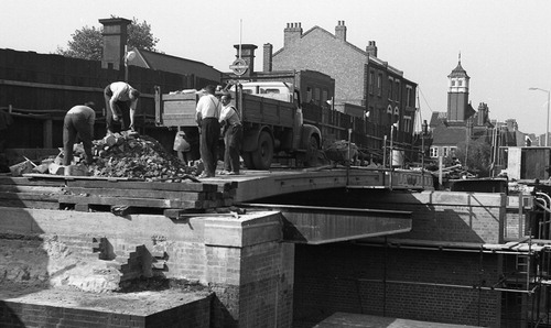
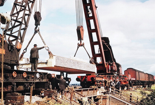
Mass concrete as a main structural material was first used in arch bridges including the Glenfinnan Viaduct of 1899.Citation20 For the Cannington Viaduct near Lyme Regis in 1903 all materials were placed using an aerial ropeway.Citation21 Reinforced concrete was apparently first used for an underbridge in 1907–08Citation22 and by the Great Central Railway in 1915Citation23 but developed slowly in mainland Britain.Citation24 A 5ft span precast concrete underbridge had been built in Northern Ireland in 1910 followed by other slab and beam bridges.Citation25 Several Irish engineers then moved to England including W. K. Wallace and W. F. Beatty (who eventually became Chief Engineer of the LMS and Chief Civil Engineer of British Railways [LM Region] respectively). A precast beam bridge with three spans of 37 ft followed at Northampton in 1937.Citation26 On London Transport in 1934 a 42 ft span over South Harrow Station concourse was cast alongside the tracks and rolled inCitation27 and in the same year a precast beam bridge was built at Stockton. Shortages of steel and timber during the Second World War encouraged the use of precast concreteCitation28 and in 1943 the LMS Railway manufactured 200 prestressed beams for the Ministry of War for emergency construction.Citation29 shows an overbridge at Queen’s Park Station being widened in 1962 using wartime stored prestressed beams.
FIGURE 2. Widening of overbridge at Queens Park Station in 1962 using wartime stored prestressed beams. Collection of Martin Welch.
In 1947 the first prestressed concrete underbridge was built, namely the Adam Viaduct near Wigan.Citation30 Precast slabs then became widely used for spans up to 30 ft span, either prestressed, reinforced, or having embedded steel joists. Such bridges were formed of either two, four or six units beneath each track as limited by crane capacity, generally without structural interconnection. Second-hand flat bottom rails infilled with concrete were used for spans up to 12 ft. Bullhead rails placed side by side and bolted together without concrete had previously been used for short spans. Dr Paul Abeles of the LNER developed inverted tee beams with in situ concrete infill for overbridges, tested from 1944 and first used in 1949,Citation31 forerunner of the pretensioned PCDG beams,Citation32 later standardized by the Cement and Concrete Association.Citation33 Dr Julian Spindel of British Railways developed the shear connected rectangular beams which eliminated transverse reinforcement, allowing bridges to be built part width during phased reconstructions. Prestressed concrete was further encouraged by Frank Turton in 1961Citation34 and later developments in underbridges were described by Atkins and Wigley in 1988.Citation35
In the twenty-first century new materials including fibre-reinforced polymer are being introduced, examples being replacement of the floor on the Calder ViaductCitation36 and a footbridge at Dawlish Station.Citation39
The pre-mechanized age
Until 1900 on completion of the Great Central Railway extension into London civil engineering works were mainly effected by manual labour assisted by gin-poles, tripods, steam or hand winches, horses and inclined planes. In 1880 on the Midland Railway steam navvies were introduced ().Citation38 Components such as centring for arches and timber or metallic spans were transported on horse-drawn wagons and often erected using goliath travellers () running on timber beams, supported by timber piles across rivers ().
FIGURE 3. Steam Navvy, one of 43 used in construction of the Great Central Railway, 1894– 99. Collection of Roger Bastin.
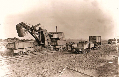
FIGURE 4. Traveller used for bridge erection, Great Central Railway, 1894–99. Collection of Leicester City Library
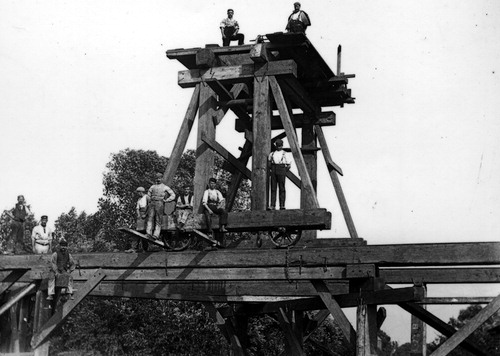
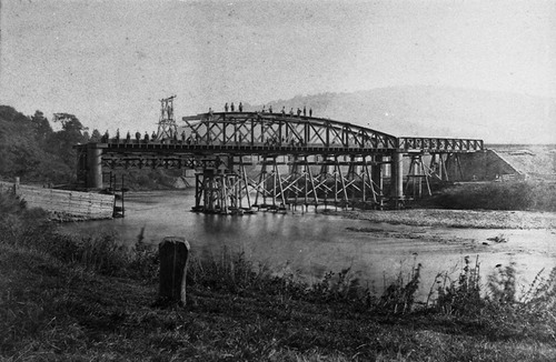
FIGURE 5. Erection of bridge over River Wye, Monmouth, 1873, supported by timber piles and using traveller. Courtesy Chepstow Museum
In Robert Stephenson’s Britannia Bridge across the Menai Strait in 1849 the box girders for the main 460 ft spans weighing 1900 tons were fabricated onshore, transferred to pontoons, floated to location between the piers and then raised vertically by 100 ft using cast-iron hydraulic presses of up to 1000 ton capacity mounted on tops of the piers.Citation39 Lifting was through a crosshead arrangement engaging by ‘clams’ onto wrought-iron chains each 6 ft length of which was removed from above after each increment of lift, followed up by masonry support. A detailed description has been given by the Resident Engineer Edwin Clark.Citation40 After erection all four spans were interconnected and continuity was achieved by jacking at the supports. In Brunel’s Royal Albert Bridge completed in 1859 each of the two spans of 455 ft weighing 1060 tons was similarly lifted by hydraulic presses.Citation41
Early substructures comprised shallow spread footings of brick or mass concrete or used timber piles to reach firm strata. Supports within rivers were either piles, brick wells or cast- or wrought-iron cylinders sunk with weights then excavated under compressed air before filling. The piling hammer machine invented by James Nasmyth was first used to drive the 13 in. square 40 ft long piles for the Newcastle High Level Bridge in 1846.Citation42 Arrol developed what are now known as modern ‘jack-up barges’, which were used for construction of the piers in replacement of the collapsed Tay Bridge.Citation43
Railway cranes
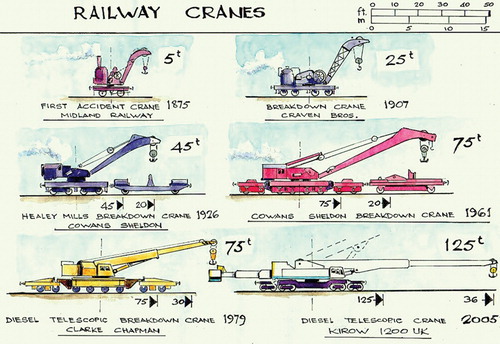
The first steam ‘accident cranes’ of 5 ton capacity in 1875 for the Midland Railway were developed from early hand cranes and larger cranes were soon needed to handle the increasing weights of rolling stock. After 1902 lifting capacities increased to 20 tons but were restricted by short jibs of 26 ft typical length. Civil engineers soon began to realize the usefulness of breakdown cranes for bridge construction. In 1908 the Great Western Railway purchased two 36 ton cranes capacity with 40 ft jibs able to lift 16 tons at 40 ft radius when propped.Citation44 From 1904 Wilfred Stokes had invented weight-relieving bogies to reduce the axle loads when travelling but which could be removed so that the crane could work closer to the load when stationary and from 1931 almost all cranes of capacity greater than 30 tons were so equipped. In 1961 twelve Cowans Sheldon 75 ton steam breakdown cranes (later converted to diesel power) were purchased with 54 ft jibs. Their capacity at maximum radius was no better than the 1908 cranes, but the longer jib achieved greater hook height for erecting overbridges. In 1979 six Clarke Chapman 75 ton diesel breakdown cranes with telescopic jib appeared with much improved capacity at maximum radius (31 tons at 39 ft radius), but by 2010 four of these became the only breakdown cranes on the main rail system whereas there were 107 in 1948.Citation45
Renewal of underbridges involved detailed planning and organization of the marshalling of cranes and materials train. Two cranes, one behind each abutment, were historically required for other than very short spans. Having removed tracks on the bridge the cranes could not offload new decks unless one crane could slew round and lift from a wagon on the next track. A method used for spans up to about 40 ft was to erect the new deck on the track occupied by the two cranes and then offload the next deck on top temporarily (). When the next track and old deck had been removed then its deck could be installed. With single tracks or for long span bridges it was necessary to offload new decks onto temporary works to one side of the bridge and to remove the old decks onto the other side of the bridge for loading onto wagons later. For erecting overbridges the short jibs of early cranes were restrictive in achieving enough hook height. With the advent of road cranes of significant capacity from the 1960s the use of railway cranes for bridge construction declined.
FIGURE 6. Erection of type A bridge near Bedford with 45 ton and 75 ton breakdown cranes, 1964. Thirty-hour possession. Author’s collection
In 2005 Network Rail contractors obtained three 125 ton Kirow cranes with telescoping/slewing counterweights having the ability to travel with a load of 28 tons at 78 ft radius, almost the capacity when blocked. These cranes have significantly improved the viability of rail cranes for bridge construction, such that one crane only is sufficient for erection of under-bridges (). illustrates the progression in crane size and capacity.
FIGURE 7. 125 t Kirow crane erecting 27 m span bridge on North York Moors Railway, 2010. Collection of Nigel Trotter
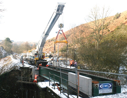
FIGURE 8. Historical progression of railway cranes. Author’s collection
For rail-over-rail bridges then railway cranes have often been the only feasible means of erection. A three-span bridge at South Hampstead carrying the Great Central Line over the West Coast Main Line was reconstructed in 1964 using 75 ton and 45 ton cranes. The site was surrounded on three sides by tunnel entrances such that space for rolling-in was impossible. This was the author’s first bridge design using modified type A decks to each of the two tracks facilitating delivery and erection over three weekend possessions ().
FIGURE 9. Reconstruction of Great Central line Bridge over Euston main lines, 1964. Three thirty-hour possessions. Author’s collection
Road mobile and other cranes
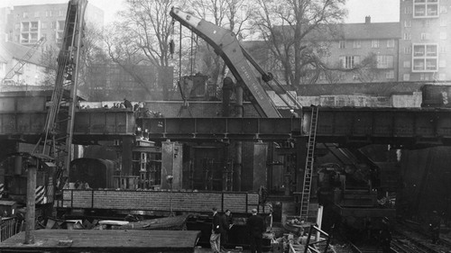
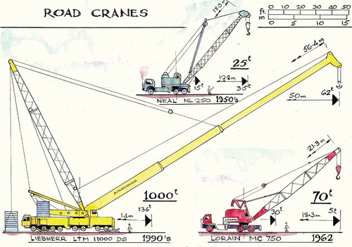
The first lorry-mounted crane appeared in 1922 with a capacity of only 2 tons but Ransomes & Rapier 6 ton cranes were made in the 1930s.Citation46 From the 1950s 25 ton road mobile cranes proliferated and were employed by contractors on railway bridges. In 1954 the 41 ton Coles Colossus became the biggest truck crane in the world and by 1962, among cranes such as the 50 ton Coles Conqueror, the largest road crane in the UK was the American 70 ton Lorain. This crane was used during the renewal of bridge No. 59 at Bushey, West Coast Main Line, in 1963 (), where the author became Resident Engineer. Rolling-in had been ruled out by the congested site. The concrete floor units were erected by forklift truck (), later also employed in reconstructing the Britannia Bridge in 1972 and Bridge No. 30 on the North Yorkshire Moors Railway in 2010.Citation47 At the Lune and Bushey bridges each of the two tracks was reconstructed separately whilst bi-directional traffic was achieved by interlacing of tracks, so avoiding point switches.Citation48 In 1964 the 100 ton Coles Centurion became the world’s largest mobile crane, so that only then did road cranes exceed the maximum capacity of railway cranes, but by 1971 the Coles Colossus had a capacity of 250 tons followed by the Colossus L6000 at 300 tons.Citation49 By the 1960s telescopic booms offered flexibility in operation. Crawler or tracked cranes from Manitowoc appeared from the USA in the 1930s capable of travelling with load on rough ground, and the ‘Ringer’ concept of extendable crawler tracks was introduced in 1962, as employed in the erection of the Glanrhyd Bridge in 1988.Citation50
FIGURE 10. Bushey Bridge, with 70 ton Lorain the then largest road crane removing wrought-iron box girders, 1963. Author’s collection
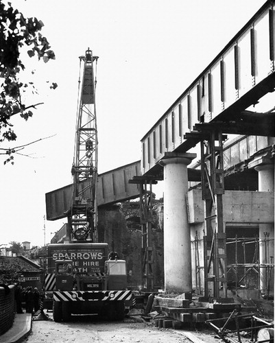
FIGURE 11. Bushey Bridge, with forklift placing precast units to form composite steel girders, 1963, whilst tracks are interlaced. Author’s collection
From the 1980s crane capacities increased to more than 1000 tons. For example the Liebherr LTM 11000 DS with a 56.4 m boom is able to lift up to 62 tons at a radius of 50 m. A 1200 ton crane erected the six U-deck spans near Arundel in 2010 (), but involved the construction of temporary roads and foundations to facilitate crane operation.Citation51 For the 29 span Hitchin Flyover a 1200 ton crane erected the 300 ton main span in 2012.Citation52 These high-capacity cranes equipped with derrick counterweight can require two days for assembly. shows the progression in size and capacity of road cranes.
FIGURE 12. A 1200 ton crane erecting 6/U-deck spans near Arundel, 2010. Courtesy Cranes & Access
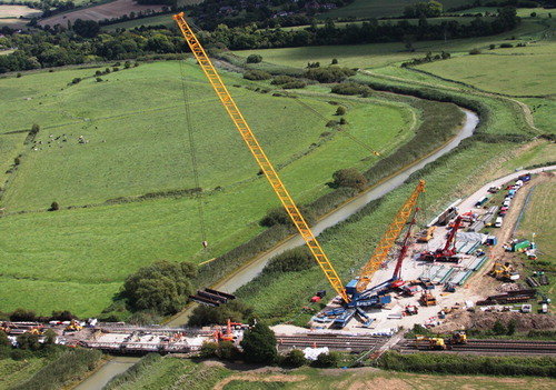
FIGURE 13. Progression of road cranes. Author’s collection
Scotch derrick cranes either static or travelling on rails had been used before the advent of large road cranes, for example the Breydon Bridge in 1903 and the Billingham Branch bridge in 1934. Derrick type cranes were used in cantilever erection of long span bridges such as the Forth Bridge, the Connel Ferry Bridge in 1903 and the Tyne Metro Bridge of 1988.Citation53 In the 1990s use of road/rail cranes has become widespread by contractors and are being used for light lifts, the largest in 2012 being the Palfinger PR750 with capacity of 14.75 tons working on rail. A combination of road/rail cranes and goliath travellers was used in the reconstruction of Leven Viaduct in Morecambe Bay in 2006, designed by the author’s firm.Citation54
Rolling-in
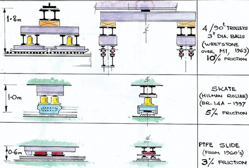
The technique of ‘rolling-in’ was developed to reduce track possessions by enabling complete spans to be pre-assembled alongside the railway, a similar process being used to remove existing decks. Installation of a truss span weighing 330 tons at Peterborough in the 1890s including removal of an existing three-span cast-iron bridge and was completed in five hours.Citation55 Rolling-in on balls can be traced back to 1880 when for the Calder Viaduct on the Wishaw Line it was noted that girders were rolled ‘by means of cast-iron balls instead of rollers such as are usually employed […] friction was reduced’.Citation56 For rolling-in normally a superstructure was supported via trolleys onto paths extending beneath the railway either in front of or on the abutments. In advance of the track possession a trial roll has traditionally been performed. During the possession tracks would be removed, the bridge winched into position, jacked up to free the trolleys, and lowered onto the permanent bearings. Traditionally steel balls (originally cast iron) of 3 inch diameter rolled on a path of bullhead rails laid flat with the trolleys incorporating jacking facilities (). Propulsion was by reeved hand or powered winches, sufficient to overcome a friction typically up to 10%. Capacity for rolling-in was restricted by a 5 ton limit on each ball, but with up to four trolleys coupled together a load of 360 tons could be taken at a support and a bridge weighing 1000 tons was installed for the M1 motorway at Whetstone in 1964.Citation57 Rolling-in was especially appropriate on overhead electrified routes.
FIGURE 14. Rolling-in with balls, skates and sliding for a 360 ton load. Author’s collection
After the Second World War military trestling () was extensively used for support of rolling-in paths and continues to play an important role in temporary works. In the 1930s Lieutenant Colonel W. T. Everall, deputy chief engineer for bridges on the North-Western State Railway in India, had developed his interchangeable trestle-staging.Citation58 He later headed the design of a range of standard spans and trestling for European wartime railway reconstruction. In the eleven months between D-Day and VE-Day 122 bridges were repaired or rebuilt in France, Belgium, the Netherlands and Germany. No less than 56,500 tons of trestling was produced mainly in the UK and in the USA.Citation59 Conversely, reconstructed road bridges used Bailey Bridging with the piers generally formed with Bailey panels. Eighty per cent of the trestling was ‘Light’ based on a 5 ft plan module, the remainder being ‘Heavy’ with a module of 6 ft. After the war the ‘Light trestling’ became known as ‘L trestling’ and latterly as ‘HYMAT-75’ as supplied by the Mabey Group.
FIGURE 15. Part of War Office drawing of military trestling, 1939. Author’s collection
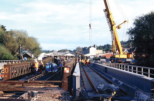
The last bridge to be rolled-in on steel balls was the three-span continuous River Exe Bridge reconstructed in 1997. The piers consisting of concrete-filled wrought-iron columns were retained and twin steel crossheads were erected from beneath the bridge, concreted together and stressed onto the columns (). The crossheads were used to support both the rolling-in paths and the permanent bearings. Temporary piling carried an extension of the paths on each side of the bridge for the new superstructures which were rolled-in on successive weekend possessions after cranes had removed the existing girders. Short-stroke rams were used for propulsion as an update of traditional winching but rolling-in on balls is now obsolete. The reactions were adjusted by jacking so that loads on the existing columns were not increased despite the bridge being heavier with ballasted track. The bridge had a chequered career being first opened in 1846 as a single track for Brunel’s atmospheric system in timber with eight spans, doubled using a wrought-iron structure to carry the up line in 1861, all replaced by three spans in steel lattice girders and wrought-iron columns in 1896.Citation60 In 1943 the floor was replaced by new cross-girders with a precast floor, supplemented by railbearers in 1950. In 1992 a number of lattice members fractured and were repaired.Citation61 The replacement design by the author’s firm comprises half-through plate girders to each track with composite floor.Citation62
FIGURE 16. Exeter River Exe Bridge, one track rolled in from each side, 1997. Author’s collection
Sliding-in
In the 1960s the London Midland Region of British Railways was designing longer span in situ concrete bridges to cross new motorways, which were significantly heavier such that rolling-in was impracticable. Sliding trials using sledges faced with polytetrafluorethelene (PTFE) on stainless-steel paths were conducted at Crewe in 1965, following which the first slide-in was achieved at Rowley Regis in a single span weighing 1500 tons in 1967.Citation63 A three-span skew concrete box girder bridge at Clifton over the M6 weighing 2700 tons followed in that year. At the intermediate piers coupled sledges were each surmounted by a Freyssinet flat jack for raising/ lowering and to equalize the 1000 ton reaction. The sliding surfaces were Glacier DU (sintered bronze impregnated with PTFE) onto twin steel billets incorporating stainless-steel strips above a concrete support track. Traction was by four 10 ton diesel winches reeved for a pull of 400 tons, but the maximum recorded force was only 70 tons equivalent to 2.6% friction. Some rippling of the stainless steel occurred during the slide but this was ironed out by the leading sledge. Difficulties arose with flat jacks and in later bridges they were only used to equalize the reaction.Citation64
In 1979 problems arose with sliding the 4000 ton highly skewed two-span Harbledown Bridge near Canterbury during a 52 hour possession, which became stuck. The sledges were mild steel lubricated with molybdenum oil on stainless steel strips which rucked up, the supporting temporary works distorted and crabbing occurred. After strengthening of the supports and insertion of a PTFE slip layer the slide was completed some 195 hours late.Citation65 After this British Rail imposed tighter control on tolerances and procedures for trial sliding. Later slides included the 120 m span Brinnington Bridge 70A over the M63/M66 motorways weighing 2500 tons in 1988 ().Citation66 Skates have been used as an alternative to sliding surfaces including ‘Slingsby — Verrolec’ and ‘Hilman Rollers’. Friction values are higher (typically 8%) but skates are more tolerant to site conditions.
FIGURE 17. Sliding-in of Brinnington Bridge 70A over M63 and M66, 1988. Courtesy Cass Hayward LLP
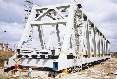
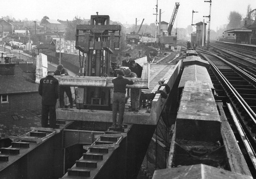
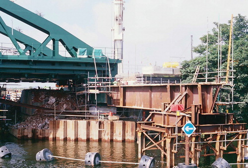
Reconstruction of the 77 m span Newark Dyke Bridge in 2000 involved sliding to remove the existing and install the new structure (). The existing bridge had a separate superstructure to each of the two tracks which were offset longitudinally to accommodate the highly skew waterway such that the abutments were of dogleg shape in plan. The superstructures had been replaced in 1896 with steel double intersection Whipple-Murphy trusses, built piecemeal on staging, which suffered from significant corrosion and brittle fracture failure of a diagonal member. Reconstruction became necessary as repairing became uneconomic. The new superstructure carrying both tracks has a square main span with a short precast bridge at the ends to accommodate the skew. The existing abutments are effectively bypassed by piled foundations formed on each side of the railway supporting a steel box ‘needle beam’ inserted through the abutments before the main possession to act both as the sliding-in path and to support the bridge permanently (). Assembly of the superstructure was carried out south of the waterway and launched across, supported at the leading end on slide tracks and at the rear by transporters preparatory to the sliding-in possession.Citation67 The new superstructure designed by the author’s firm comprises steel bowstring trusses carrying a composite floor of comparatively rigid form to cater for high speed trains, this being the first bridge in the UK designed to dynamic criteria for speeds more than 125 mph.Citation68
FIGURE 18. Newark Dyke Bridge as completed 2000, showing needle beam. Author’s collection
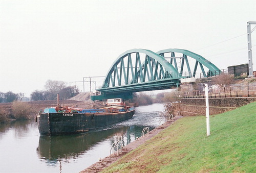
FIGURE 19. Newark Dyke Bridge, sliding-in using permanent needle beams, 2000. Seventytwo- hour possession. Author’s collection
Launching
Erection of underbridges by launching along the track alignment has been adopted across waterways but was normally only feasible on new routes or where tracks could be temporarily closed or diverted. In 1947 during floods one pier of the six span River Wye Bridge at Strangford collapsed due to scour. It was decided not to rebuild the pier but replace the two adjoining spans by a 27.7 m span launched on rollers from on top of the adjacent spans assisted by a temporary nose. For the new Selby Diversion line in 1982 the two 37 m and 25 m steel spans over the River Aire were coupled together and launched using 115 ton capacity rollers.Citation69 In 1986 London Transport bridge D29 at Hanger Lane over the main lines from Paddington was replaced with a 50 m truss span using a combination of longitudinal and transverse roll-in.Citation70
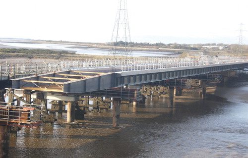
In 2012–13 the Loughor Viaduct over the river estuary near Swansea was reconstructed, being designed originally by Brunel and completed in 1852 as a timber trestle viaduct 750 ft long in 40 ft spans. Wrought-iron girders replaced the superstructure in the 1880s, being further replaced by steel in 1909 when new timber trestles were installed, supported on the original timber piles. Refurbishment was carried out between 1979 and 1981 and the line was single-tracked with speed restriction in 1986. The reconstructed bridge for twin tracks has six 36 m continuous spans on new supports each comprising a 1.2 m diameter pile either side of the bridge constructed from jack-up barges. Concrete crossheads were built on temporary slide beams and slid beneath the existing bridge. The new steel girders were assembled alongside the existing track beyond the west abutment preparatory to launching by sliding on temporary supports at each pier () followed by concreting of the floor slab and laying of twin tracks. The complete structure was slid-in during a 250 hour possession.Citation71
FIGURE 20. Loughor Viaduct, offline launching, prior to transverse slide in possession, 2013. Author’s collection
Existing bridges have been used as launchways where long track closure was possible. The 300 ft river span of Brunel’s 1852 Chepstow Wye Bridge was replaced in 1962 during a six-week closure of each of the two tracks. Each steel deck type truss weighing 290 tons was assembled underneath the approach spans and then launched between the existing cast-iron pier cylinders, slung from trolleys moving along runway beams bolted to the underside of the existing bridge which was progressively demolished using the new span as a working platform.Citation72
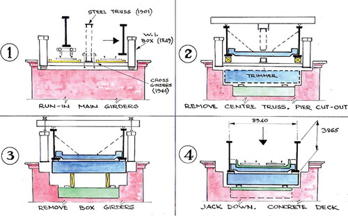
In the Gainsborough River Trent Bridge of 1849 the two 50 m river spans comprised continuous wrought-iron box girders and cross girders with timber floor. In 1901 it was strengthened by inserting a steel truss between the two tracks and one of the main girders was moved laterally to accommodate the wider ‘six-foot’. The lengthened box cross girders were replaced by steel I-sections in 1961 but by the 1980s suspected fatigue cracking occurred in one of the boxes over the intermediate pier and elsewhere necessitating reconstruction. British Rail adopted a then novel ‘design and construct arrangement’ involving a three-month track occupation. The new superstructure designed by the author’s firm comprises half through plate girders with composite floor (see ). The extra bridge width became beneficial because the new main girders could be launched inside the existing girders and furthermore be utilized to remove them. shows the sequence. The new girders, made in three lengths, were launched across the bridge on rail bogies, slid sideways until contacting the existing girders to which they were secured and temporarily supported by existing cross girders. Overhead gantries, running on rails which had been placed on top of the new girders, sequentially erected new cross girders and removed the centre truss in sections to the end of the bridge, lifted clear by crawler crane. Masonry in the piers was then reduced in height between the existing main girders to allow insertion of steel trimmers to support the new girders on inboard bearings. The gantries then lifted the existing girders balanced on each side and after cutting adjacent to the centre pier into two sections they were moved towards the end of the bridge where a crawler crane progressively removed them. The new girders were then jacked down onto the trimmers and the deck slab concreted. Reducing the pier masonry made it possible to accept the weight of a concrete deck so that there would be no additional loadings on the existing foundations.Citation73
FIGURE 21. Gainsborough River Trent Bridge, 1992, erected by launching on existing bridge. Courtesy Cass Hayward LLP
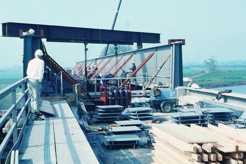
FIGURE 22. Gainsborough River Trent Bridge, sequence of construction, 1992. Author’s collection
A number of overbridges have been erected by launching and the first incrementally launched concrete bridge in the UK was the Shepherds House Bridge carrying the A4 road across the Great Western main line near Reading in 1977.Citation74 Composite bridges at Crewe in 2001 and near Durham in 2004 were launched over main lines using inverted skates, pulled by winch and by strand jacking respectively.Citation75 At Bishop’s Bridge Road Bridge at Paddington Station in 2006 designed by the author’s firm the existing 65 m main span truss bridge weighing 800 tons was raised before launching the new deck beneath it and then lowering the old bridge onto Transporters for removal.Citation76
Occasionally it has been possible to construct underbridges ‘on-line’ whilst the railway is temporarily realigned. An example was the Lyne Bridge near Chertsey over the M3 motorway in 1979, a highly skewed 2/55 m span post-tensioned concrete cable-stayed structure weighing 4500 tons. The railway was retained by a sheet piled wall whilst the ground alongside was excavated to construct the bridge.Citation77
Self-Propelled Modular Transporters (SPMTs)
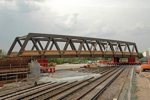
Transporters comprising multiple interlinked powered axles with vertical jacking ability were developed for manoeuvring heavy loads in offshore and other industries. They have the ability to manoeuvre heavy loads in any direction. Since the 1980s they have been used increasingly for erection of complete bridges. Temporary works are largely eliminated except for elevated supports to position the transporters beneath the load. A typical capacity is 30 tonnes on each axle occupying a plan area of 3.0 m × 1.5 m, with a platform height of 1.4 m. An example in 2011 was the New Cross Gate Bridge to carry the East London Line where a 75 m span truss was assembled at ground level, concreted and then jacked up to allow transporters to be positioned. During a weekend possession the 1000 tonne load was transported a distance of 100 m, manoeuvred across four protected railway tracks and jacked down onto its bearings (see ).Citation78 In Reading for the Caversham Road Bridge replacement in 2010 transporters removed the existing bridge and erected a new 1000 tonne steel deck. Transporters demand an adequate surface for support and movement. A delay of several days occurred in positioning of the Battlefield Bridge (referred to below) during a possession at Christmas 1999 when heavy rains led to mired ground.
FIGURE 23. Erection using Transporters of New Cross Gate Bridge, East London Line, 2010. Courtesy Mabey Bridge
Substructures
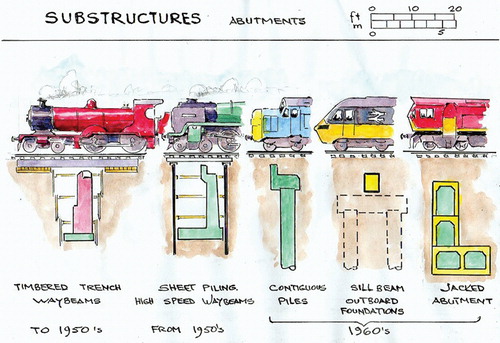
Once railways were built then the time-consuming works in substructures for new bridges had to be performed whilst trains were running. shows methods used for construction of abutments beneath tracks. Until the 1960s substructures were usually built within timbered or sheet piled trenches beneath the tracks spanned by temporary waybeams on pads of timber sleepers whilst speed restrictions of 5 or 10 mph were imposed.Citation79 High-speed waybeams of steel troughing were developed in the 1960s but new methods were then developed to reduce traffic restrictions. Contiguous concrete bored piles eliminated the need for temporary trenches, for example on the Altofts Junction Bridge 219B built for the M62 motorway in 1971, also the first UK railway bridge to use high tensile steel in its 43.3 m span type ‘E’ superstructure. Mini-piles driven within limited headroom have been employed for example the Daer Viaduct replacement where new abutments were constructed in front of those existing. The new deck was built below and around the existing and then jacked up during a possession once the existing deck had been taken out.Citation80
FIGURE 24. Historical progression of construction of abutments. Author’s collection
Outboard foundations where footings or piles on both sides of the railway are spanned by sill beams to support the superstructure have increasingly been adopted to reduce working beneath tracks. In 1972 the foundations of a bridge at West Heath, Farnborough, on the four-track Bournemouth main line comprised spread footings formed clear of the tracks and spanned at each abutment by a steel box girder. For the Battlefield Bridge on the Shrewsbury to Crewe line in 1999, designed by the author’s firm, large diameter piles on each side of the railway support the cantilever outstands to a single element in situ reinforced concrete slab deck. During a weekend possession the bridge was moved into position by Transporters after removal of the embankment fill.
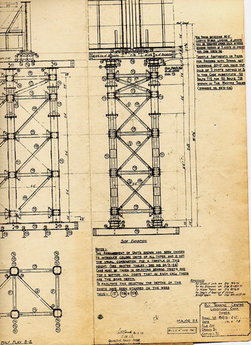
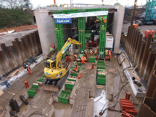
The technique of pipe-jacking (or thrust boring) had been introduced into the UK in the 1950s to construct sewers, culverts and subways up to 3 m in diameter. It involves thrusting prefabricated pipes from a prepared pit, with a shield in front to cut and support the ground whilst spoil is removed through the pipe by mining. An important development by Tube Headings Ltd and the Western Region of British Railways was to use rectangular units, later concrete filled, to form the abutments for Alphin Brook Bridge near Exeter in 1967. This avoided railway disruption except for speed restrictions during actual jacking.Citation81 Later bridge abutments and piers were composed of multi-tiered units vertically stressed together designed by Cementation Ltd but proved to be expensive (see ). Problems with track disturbance arose especially where cover was limited.Citation82 Drag sheets were developed to reduce friction between the roof of units and the overlying ground. In situ concrete boxes forming complete bridges have been formed by jacking from one or both sides of the track.Citation83 Where cover has been limited tracks have been supported independently during jacking of portal frame bridges at Pontypridd and Bedford similar to the Petrucco-Verona system used in Italy.Citation84
FIGURE 25. Brentwood Bridge over M25 showing tiered abutment walls during jacking beneath tracks, 1974. Collection of Roger Bastin
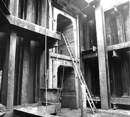
In recent years various techniques have been employed to reduce the need for speed restrictions by jacking or pulling complete portal frame or integral bridges in excavated cuts during extended weekend possessions having previously constructed the foundations as jacked boxes or by piling from within concrete or steel circular tunnels (see ). At Tipton in 2009 a box 19 m wide 58 m long weighing 6500 tonnes was jacked in open cut during a 101 hour possession to remove the last road level crossing on the West Coast Main Line (see ).Citation85
FIGURE 26. Jacked and pulled structures. Author’s collection
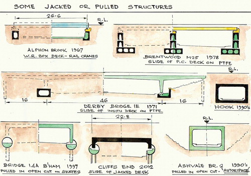
FIGURE 27. Tipton, 2009. Jacking in open cut of box weighing 5500 t. One hundred-and-onehour possession. Courtesy CH2M Hill Halcrow & BAM Nuttall
Concluding remarks
Throughout railway history engineers have applied their ingenuity to construct bridges using the techniques and equipment of the time. Advances since the Second World War have revolutionized the sizes and weights which can be handled, allowing whole bridges or spans to be installed in one piece. However stricter safety requirements and the use of multiple organizations have not always resulted in shorter possessions of the railway. The single control and early principles of construction exercised by the nineteenth-century pioneers then provide lessons now.
Additional information
Notes on contributors
Alan C. G. Hayward
Alan Hayward originally trained from 1957 as a railway civil engineering apprentice, following which all his career has been in bridge design and construction. He had extensive experience with contractors and consulting engineers before co-founding the bridge specialists Cass Hayward Consulting Engineers in 1983. He has designed more than 200 bridges for railways, highways, footways and roll-on/roll-off linkspans, with eight national awards. He instigated the U-deck single element bridge concept, now a Network Rail standard. He is a consultant to Cass Hayward LLP, Fellow of the Royal Academy of Engineers and a Chartered Civil and Structural Engineer.