
Abstract
Three advanced nuclear power systems use liquid salt coolants that generate tritium and thus face the common challenges of containing and capturing tritium to prevent its release to the environment. The fluoride salt–cooled high-temperature reactor (FHR) uses clean fluoride salt coolants and the same graphite-matrix coated-particle fuel as high-temperature gas-cooled reactors. Molten salt reactors (MSRs) dissolve the fuel in a fluoride or chloride salt with release of fission product tritium into the salt. In most FHR and MSR systems, the baseline salts contain lithium where isotopically separated 7Li is proposed to minimize tritium production from neutron interactions with the salt. The Chinese Academy of Sciences plans to start operation of a 2-MW(thermal) molten salt test reactor by 2020. For high-magnetic-field fusion machines, the use of lithium enriched in 6Li is proposed to maximize tritium generation—the fuel for a fusion machine. Advances in superconductors that enable higher power densities may require the use of molten lithium salts for fusion blankets and as coolants.
Recent technical advances in these three reactor classes have resulted in increased government and private interest and the beginning of a coordinated effort to address the tritium control challenges in 700°C liquid salt systems. We describe characteristics of salt-cooled fission and fusion machines, the basis for growing interest in these technologies, tritium generation in molten salts, the environment for tritium capture, models for high-temperature tritium transport in salt systems, alternative strategies for tritium control, and ongoing experimental work. Several methods to control tritium appear viable. Limited experimental data are the primary constraint for designing efficient cost-effective methods of tritium control.
I. Introduction
Recent technology advances are creating growing interest in three nuclear technologies that require high-temperature salt coolants: (1) fluoride salt–cooled high-temperature reactors (FHRs) with solid fuel and liquid salt coolants, (2) molten salt reactors (MSRs) with the fuel dissolved in the salt coolant, and (3) high-magnetic-field fusion machines with immersion salt coolant blankets. In each system the coolant is a high-temperature liquid salt that produces tritium; thus, there is the common technical challenge of tritium control and capture in salt at temperatures typically between 600°C and 700°C. Hydrogen (tritium), unlike other elements, can diffuse through metallic heat exchangers and escape the reactor system. To avoid exceeding allowable tritium releases to the environment, tritium removal from the salt coolant and barriers is required.
Two sequential workshops were held to address common challenges: (1) Workshop on Tritium Control and Capture in Salt-Cooled Fission and Fusion Reactors: Experiments, Models and BenchmarkingCitation1,Citation2 and (2) FHR Integrated Research Project (IRP-2) Workshop 2: Benchmarking.Citation3 The workshop objectives were to bring together researchers involved in experiments, modeling, and benchmarking for tritium control at ∼700°C in liquid salts and related systems to (1) exchange information, (2) initiate an effort for benchmarking of experiments and models, and (3) encourage cooperation between different groups working on the same challenges.
This critical review summarizes both workshop results including descriptions of the power systems that use high-temperature salts (Sec. II), the common chemistry and tritium challenges (Sec. III), ongoing work removing tritium using carbon (Sec. IV), other technologies for tritium control (Sec. V), and tritium barriers (Sec. VI).
II. Salt-Cooled Power Systems
There is a rapidly growing interest in fission and fusion systems using salt coolantsCitation4,Citation5 that is driven by separate developments in (1) FHRs, MSRs, and fusion and (2) gas turbine power systems that can couple to salt-cooled reactor systems. The interest in developing these technologies is the driving force for the need to develop tritium control technologies in 700°C salt.
The choice of salt depends upon the application, but in most cases the baseline coolant is a lithium-beryllium-fluoride salt known as FLiBe (7Li2BeF4) because it has the best thermal-hydraulic and neutronic properties. However, it does generate tritium if irradiated. There have been many studies comparing salts for specific applications.Citation6–Citation11 The characteristics of the FLiBe as well as some of the other potential salts are listed in .
TABLE I FHR Coolant OptionsTable Footnote*
All proposed salts are multicomponent salts to lower the melting points. The primary coolant system is a closed loop that operates at atmospheric pressure with nominal core coolant inlet and outlet temperatures of 600°C and 700°C, respectively.
II.A. Salt-Cooled Power Systems
II.A.1. Fluoride Salt–Cooled High-Temperature Reactors
The FHR (CitationRef. 12) uses salt coolant and the graphite-matrix coated-particle fuel developed for high-temperature gas-cooled reactors (HTGRs). Advances in the fuel are enabling the development of the FHR. Because the FHR uses a proven fuel and a clean salt coolant, it is the near-term commercialization option for a salt-cooled reactor. Three different fuel designs are proposed by different groups ():
Pebble bed: The pebble-bed FHR (CitationRef. 13) uses 3-cm-diameter graphite pebbles with embedded coated-particle fuel, which is the same basic fuel geometry that was used in the German HTGRs and will be used in the Chinese HTGRs that are under construction. The pebble-bed design is the most developed of the salt-cooled FHR designs. The Chinese Academy of Sciences (CAS) plans to build a 10-MW(thermal) pebble-bed FHR test reactor in the next decade. Like pebble-bed HTGRs, this design allows online refueling. Because carbon adsorbs tritium, there is the potential option in this reactor of using the fuel pebbles as a tritium removal system. It is the near-term FHR option.
Plate fuel: Oak Ridge National LaboratoryCitation14 (ORNL) is developing a plate fuel where the hexagonal fuel assembly is similar in shape to a sodium-cooled-reactor fuel assembly. The fuel plates are made of a carbon-carbon composite with the coated-particle fuel on the plate surfaces. It is a “traditional” type of fuel assembly with a refueling strategy similar to a sodium fast reactor, which is another low-pressure reactor.
Fuel inside radial moderator (FIRM): This FHR core designCitation15,Citation16 is somewhat similar to the 14 operating British advanced gas-cooled reactors (AGRs) except for use of a salt coolant, higher power densities, and the details of the fuel design. The AGRs are graphite-moderated carbon dioxide–cooled high-temperature reactors with gas exit temperatures of 650°C. The AGR fuel consists of UO2 pellets in stainless steel pins with an assembly consisting of a circular array of pins inside an annular graphite shell. The reactor core is graphite with vertical cylindrical channels for the fuel assemblies.
Fig. 1. Alternative FHR fuel designs.
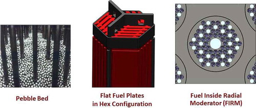
The FHR FIRM assembly replaces the AGR fuel assembly with a graphite cylinder containing liquid-salt cooling channels and fuel channels filled with coated-particle fuel in carbon-matrix pellets, which is a cylindrical variant of the prismatic fuel blocks used in some HTGRs. FIRM assemblies would be refueled using the same refueling strategies used by the AGR, pulling assemblies straight up through the vessel cover. AGRs refuel online at ∼650°C, similar to FHR operating temperatures.
The baseline coolant is FLiBe because it has the best thermal-hydraulic and neutronic properties, but it has two drawbacks: Isotopically separated 7Li is expensive, and beryllium is toxic. The other salts can be used but with neutronic or thermal-hydraulic penalties. All the concepts have operating temperatures between 600°C and 700°C, respectively. The lower temperature is partly based on being significantly above the melting points of these salts, and the higher temperature is based on existing commercially qualified materials for primary heat exchangers. Because FHRs use liquid rather than gas coolants, their power densities are four to ten times higher than comparable gas-cooled reactors.
II.A.2. Molten Salt Reactors
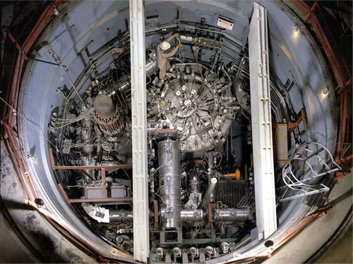
Molten salt reactors were first developed as part of the aircraft nuclear propulsion program in the 1950s and then as thermal-neutron-spectrum breeder reactors using the thorium fuel cycle in the 1960s. The Molten Salt Reactor Experiment (MSRE), an 8-MW(thermal) reactor (), successfully demonstrated the technology in the late 1960s. This reactor used FLiBe salt with fuel and fission products dissolved in the salt. The reactor used bare graphite as the neutron moderator. The program was canceled in the early 1970s when the United States decided to focus its breeder reactor program on sodium-cooled fast reactors (SFRs). Partly because of changing goals and partly because of technological advances over the last several decades in other fields that have addressed some of the MSR developmental challenges, in the last decadeCitation17–Citation20 there has been a renewed interest in MSRs for several reasons:
Fuel cycle versatility: MSRs can operate on a variety of fuel cycles including thorium breeder fuel cycles and various cycles that destroy actinides. This capability has been increased by recent work to develop fast-spectrum MSRs.
Advancing technology: Many of the technology challenges of the 1960s have been reduced or eliminated thanks to advances in other fields. Better high-temperature carbon forms can provide longer-lasting materials for reactor internals. New materials may enable high-temperature (>1000°C) distillation to simplify removal of fission products from the liquid fuel salt.
Safety: MSRs enable alternative safety strategies relative to solid fuel reactors including (a) dumping the liquid fuel to critically safe passively cooled tanks under any accident scenario and (b) potentially minimizing the inventory of longer-lived fission products such as cesium in the reactor that may dominate the accident source term and the potential for land contamination. The second option is enabled by the advanced separation technologies to remove and solidify selected fission products while the reactor is online.
Fig. 2. Molten Salt Reactor Experiment.
Three classes of MSRs are being investigatedCitation20 with different characteristics but with common high-temperature salt challenges:
Thermal-neutron-spectrum MSRs: These MSRs use fluoride salts with fuel dissolved in the salt and graphite in the reactor core to create a thermal neutron spectrum. The MSRE was this type of MSR. The CAS plans to build a small 2-MW(thermal) MSR by 2020 with an emphasis on the thorium fuel cycle for fuel sustainability.
Fast-spectrum MSRs: These MSRs use either fluoride or chloride salts with fuel dissolved in the salt. There are no neutron moderators in the system. Examples include the European concept that uses a lithium heavy-metal fluoride salt and the Terrapower breed-and-burn concept that uses a chloride salt. For high breeding ratios, chloride fast-spectrum reactors require isotopically separated 37Cl.
Fast-spectrum pin MSRs: These MSRs (CitationRef. 21) use two molten salts with reactor designs somewhat similar to SFRs. The fuel pins contain liquid chloride salts with dissolved fuel. A second clean liquid salt is used to cool the fuel assemblies. The replacement of solid fuel in the fuel pins with a liquid fuel salt (a) allows higher temperatures, (b) enables a traditional fast reactor with a large negative temperature coefficient due to expansion of the liquid fuel with temperature, (c) minimizes stresses on the cladding, and (d) provides a simplified method to recycle fuel or replace cladding.
II.A.3. High-Magnetic-Field Fusion Reactors
Advances in magnetic fusion may drive fusion systems to use liquid salt coolants. For any given fusion power level, the size of a magnetic fusion device is proportional to one over the magnetic field to the fourth power. Practical fusion machines require superconducting wire or tape to generate the magnetic fields while minimizing electrical consumption by the magnets. However, superconductors lose their superconducting properties in high magnetic fields.
In the last 5 years, methods have been developed to manufacture rare-earth barium copper oxide (REBCO) superconductor tapes. This superconductor enables magnetic fields at the coil >22 T, which is more than twice the capability of older superconductors.
REBCO superconductors may enable doubling the practical peak magnetic field in a fusion machine and thus reduce the volume of fusion systems by an order of magnitude. The radius of a 500-MW plasma fusion system would be ∼3 m, which is the size of several magnetic fusion devices already built with power levels of ∼10 MW. shows JET (an existing fusion experimental device in the United Kingdom) and the proposed high-magnetic-field fusion system based on REBCO superconductors.Citation22 shows the high-magnetic-field fusion system in more detail.
Fig. 3. Impact of higher-field superconductors on the size of magnetic fusion system.
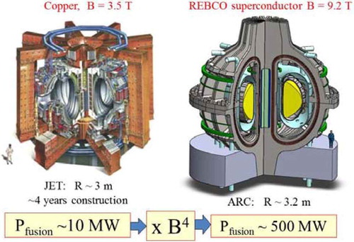
Fig. 4. ARC concept with salt blanket (blue) and demountable superconducting REBCO magnets.
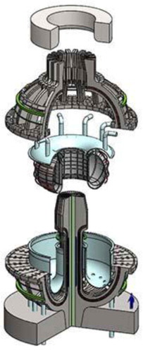
Increasing fusion power density by an order of magnitude improves long-term economic viability. However, it imposes major changes in fusion blanket design because of the higher power densities. Historically proposed blankets have been solid lithium-containing materials for production of tritium fuel (6Li + n → 3H + 4He). The higher power densities will likely require changing to a liquid blanket () containing lithium, most likely FLiBe (66.76LiF-33.3BeF2). With a liquid blanket (blue in and ), it is easier to assure effective neutron shielding (no holes or cracks) with ultrahigh radiation levels. Fusion generates ∼17 MeV per fusion of tritium and deuterium; most of this energy is in the form of 14-MeV neutrons. The liquid salt slows down the neutrons, captures the neutrons to produce tritium, and absorbs the heat (14 MeV) in the liquid. The heat transfer challenges in solid fusion blankets become very difficult at these very high power densities.
The liquid blanket choices are (1) FLiBe or (2) a liquid metal coolant containing lithium (lithium, lead-lithium, etc.). A lower-electrical-conducting liquid salt rather than liquid lithium or a lead-lithium eutectic is preferred to ease magneto hydrodynamic issues such as coolant pumping and plasma control with the very large magnetic fields associated with these new superconductors.
II.B. Nuclear Air-Brayton Combined Cycles
Salt coolants were originally developed for the Aircraft Nuclear Propulsion Program in the 1950s with the goal of coupling a nuclear reactor to aircraft jet engines. They were chosen because they could meet the requirements of the jet engines, delivering heat to the power cycle between 600°C and 700°C. Recent advances in utility natural gas combined cycle technologies now enable coupling these reactors to an open nuclear air-Brayton combined cycle (NACC) or closed Brayton power cycle. This enables providing baseload electricity with additional variable peak electricity produced by using auxiliary natural gas, biofuels, hydrogen, or stored heat to (1) increase nuclear plant net revenue by 50% to 100% relative to baseload nuclear plants and (2) enable a low-carbon nuclear renewable electricity system. These developments create large incentives to develop salt-cooled reactors.
During baseload operation () of a NACC (CitationRefs. 23 through Citation26), atmospheric air is filtered, the air is compressed, heat is added from the reactor through a liquid-salt coiled-tube heat exchanger, the hot compressed air goes through a turbine to produce electricity, the air is reheated and goes through a second turbine, the warm air exiting the gas turbine goes through a heat recovery steam generator to generate steam that is used to produce added electricity, and the air is exhausted to the stack. If coupled to a salt-cooled reactor delivering heat between 600°C and 700°C, heat-to-electricity efficiency is 42%. This specific example uses a modified General Electric 7FB gas turbine.
Fig. 5. Nuclear air-Brayton combined cycle.
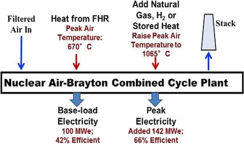
The baseload NACC temperatures, determined by heat exchanger material temperature constraints, are far below maximum peak gas turbine temperatures. Thus, there is the option of adding heat (natural gas, stored heat, etc.) after the nuclear heating to further raise compressed gas temperatures before entering a power turbine—a topping cycle. The incremental heat-to-electricity efficiency depends upon the design, ranging from 66% to 70%—a thermodynamic topping cycle. This is the most efficient system known to convert heat to electricity based on existing technology and far above the 60% efficiency of stand-alone combined cycle natural gas plants.
An economic analysisCitation27 was done on the performance of a FHR with NACC using natural gas to produce peak electricity in the California and Texas markets. The peaking capability increased the plant yearly revenue by ∼50% after subtracting the cost of the natural gas compared to a baseload nuclear plant. Because NACC is more efficient than a stand-alone natural gas combined cycle plant in converting natural gas to electricity (uses less natural gas), its electricity production costs for peak electricity are less than a stand-alone natural gas plant; thus, it earns large profits when electricity prices are set by natural gas plants.
The addition of wind and solar in some electricity grids has resulted in significant hours per year with very low electricity prices.Citation28–Citation30 In such utility systems it is proposed that a firebrick resistance-heated energy storage (FIRES) systemCitation26 replace the use of natural gas for providing heat to produce peak electricity in the NACC power cycle. FIRES consists of high-temperature firebrick heated to high temperatures with electricity at times of low or negative electric prices. For peak electricity production, the compressed air after nuclear heating is sent through the firebrick to raise its temperature before going to the turbine. The round-trip storage efficiency from electricity to heat to electricity is ∼66%, based on ∼100% efficiency in resistance electric conversion of electricity to hot firebrick and 66% efficiency in conversion of incremental heat to electricity within NACC. FIRES enables the reactor to operate at baseload at all times while the station buys electricity from the grid at times of low prices to charge FIRES, sends its own electricity to FIRES at times of low prices, and sells electricity at times of high prices.
Such power cycles impose added requirements on tritium control systems. In steam and similar closed power cycles, heat is rejected to cooling water through cold heat exchangers. The diffusion rates of tritium through cold heat exchangers are low, and thus, the heat exchanger is a good barrier against tritium escape. In a gas turbine, cycle heat is transferred from salt to compressed air through hot heat exchangers with much higher rates of tritium diffusion. Containing tritium in the salt-cooled reactor with a NACC is more challenging.
III. Salt Chemistry and Tritium Generation
summarizes some of the differences and similarities in salt coolant requirements among the different reactor concepts. Carbon in the system can have a large impact on system behavior because carbon can absorb tritium and other impurities in the salt and has other chemical impacts. The choice of salt depends upon neutronic and thermal-hydraulic considerations.
TABLE II Salt Characteristics of Different Systems
Most proposed salts contain lithium because of its ability to lower the melting points of these salts to a few hundred degrees Celsius. For the FHR and MSR, one wants low neutron absorption cross sections with minimum tritium production. If a lithium salt is used, isotopically separated 7Li must be used to minimize neutron absorption and tritium production. There are other salt choices for the FHR and MSR, and all of the options involve complex trade-offs. For fusion, one wants to maximize tritium production (the fuel), and thus, 6Li is used to maximize tritium production. For fusion systems, FLiBe is the required salt coolant because it maximizes tritium production.
Under neutron irradiation, lithium fluoride–beryllium fluoride salts generate tritium by multiple pathways:
(1)
(2)
(3)
(4)
and
(5)
Lithium-7 has a very small neutron cross section, and 6Li has a large neutron cross section that maximizes tritium generation rates. With 7Li salts, the residual 6Li will partly burn out but will not go to zero if the salt also contains beryllium. Neutron reactions with beryllium will generate 6Li that is converted into tritium.
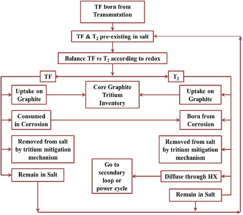
The nuclear reactions have important chemical implications. With appropriate materials of construction, clean salts have extremely low corrosion rates. This was demonstrated in the MSRE where the secondary loop used FLiBe with very low corrosion rates. However, in a reactor under neutron irradiation, LiF is converted to 3HF—hydrogen fluoride. Hydrogen fluoride is corrosive. Corrosion in salt-cooled reactors (fission or fusion) is directly tied to the production of tritium. Tritium control and corrosion control cannot be separated.
If 3HF is allowed to corrode metals of construction, tritium in its molecular form will be generated. To avoid corrosion, redox control agents can be added to the coolant for converting 3HF to 3H2. The redox potential determines the relative amounts of 3HF versus 3H2. While the 3HF cannot escape the system, atomic 3H from 3H2 diffuses through hot metals such as heat exchangers to the environment. Maintenance of long-term system integrity by assuring low corrosion rates implies converting 3HF to 3H2, but 3H2 can escape the system requiring methods for removal of 3H2 and methods for slowing escape of 3H2 from the system. A partial pressure of 1H2 in the cover gas will lead to isotopic exchange with 3HF, producing 3H-1H, thus affecting the tritium transport rates. At the same time, introduction of H2 in the cover gas may also shift the redox potential of the salt, thus affecting corrosion control.Citation31–Citation36
Tritium generation rates depend not only upon the salt selection and whether the reactor is a FHR, MSR, or fusion machine but also on the specific design features. This is most evident in the design of FHRs where there are large variations in the fraction of the core that is salt, with a significantly higher salt fraction in a pebble-bed reactor than in a FIRM core design. For one pebble-bed FHR design, it was estimatedCitation13 that ∼0.03% of the tritium produced could be allowed to escape in order to stay below the tritium emission rates of the current fleetCitation37 of pressurized water reactors [2.2 Ci/GW(electric) · day or 810 Ci/GW(electric) · year].
Stempien et al.Citation34,Citation35 and StempienCitation36 built a model () for FHRs that accounts for tritium production, corrosion, and transport that can predict behavior and calculate the impact of different methods to limit tritium losses or capture tritium. The model has been validated with the limited experimental data that are available. More experimental data are required to validate results.
Fig. 6. TRIDENT.
Tritium Diffusion EvolutioN and Transport (TRIDENT) has been used to model a FHR with a carbon bed for tritium removal as 3H2 (the model accounts for the diffusion and removal of HF to the graphite as well). The model results are shown for one case in . In this case the carbon bed is designed to enable sufficient tritium removal to limit tritium releases to acceptable levels. TRIDENT simulates tritium production and removal with time including buildup of tritium in sinks and other transient phenomena.
TABLE III TRIDENT Output for FHR with Tritium Carbon Absorber Bed
Several conclusions follow from such modeling. The allowable tritium gas pressure in the primary system with metallic heat exchangers is on the order of magnitude of 0.05 Pa. If the tritium gas pressure is greater than this, the concentration gradients of tritium through hot heat exchangers may allow tritium to escape during operations in excess of releases from light water reactors.Citation37 The same limit would apply to a MSR or a fusion machine. The difference with a fusion machine is that the starting concentration of tritium in the salt is three orders of magnitude larger than in a FHR, and tritium is recovered from the salt for subsequent use as fuel. The calculated partial pressure of 3HF is also given, but HF cannot diffuse through hot metal. Graphite absorbs both 3H2 and 3HF.
The requirements in for allowable levels of tritium in the salt are strongly dependent upon permeation rates of tritium through hot heat exchangers to the environment. If high-performance coatings are incorporated into the heat exchangers to slow migration of tritium, higher concentrations of tritium can remain in the salt. Consequently, there is a trade-off between high-efficiency removal of tritium from the salt and highly effective barriers to slow tritium transport through the heat exchangers. Salts dissolve oxides and most other permeation barriers, and thus, in most cases the barrier would have to be on the outside of the tube. The exception is tungsten, which has a low tritium permeability and is corrosion resistant in liquid salts.
There are other incentives to minimize tritium levels in reactors. For example, if there is a higher partial pressure of tritium, there will be more sorption of tritium on carbon and other materials in the reactor core. Under accident conditions where the temperature increases, this tritium would be desorbed.
Additional incentives exist to keep tritium levels very low in the salt coolant. There is some evidence that the permeation rate for metal heat exchangers outside the reactor is surface limited below 100 Pa and varies as the hydrogen pressure whereas above 100 Pa the permeation rate is diffusion limited and varies as the pressure to the one-half power.Citation38 The practical implication is that the permeation rate decreases at a faster rate as the pressure goes below 100 Pa (surface limited), which implies the potential that permeation (tritium loss) rates may be an order of magnitude less at very low tritium pressures.
IV. Tritium Control and Carbon
Carbon in the form of isotropic graphite is used in FHRs and thermal-spectrum MSRs as a neutron moderator. The fuel microspheres designed for FHRs and HTGRs are dispersed in graphite matrix and packed as pebbles, compacts (FIRM assembly), or other geometries. There is a great deal of information about the behavior of graphite in nuclear reactors. In the United States, most of the work on nuclear-grade graphite has been done at ORNL (CitationRefs. 39 and Citation40).
The MSRE at ORNL proved that graphite can physically withstand intense neutron irradiation in high-temperature FLiBe (CitationRef. 41) and also showed significant tritium uptake in the graphite. It also identified issues that need to be mitigated: (1) Salt penetration in graphite porosity may cause local hot spots where the graphite damage may be accelerated and (2) retention of fission products (135Xe, noble metals, etc.) has an adverse effect on reactor performance by absorbing neutrons. In this context, it is important to make a clear distinction between a MSR with dissolved fuel and a FHR or fusion reactor with clean salt. In the MSR, the salt with fuel generates heat at high rates due to fission in the reactor core. If any of that salt penetrates the carbon, it brings with it the high rate of heat generation that can create a hot spot where the salt penetrates the carbon. This does not happen in a FHR or fusion machine.
The solution identified by the MSRE project and pursued currently by the CAS (CitationRef. 42) is sealing graphite porosity by surface coating with an impermeable layer of pyrolytic carbon (PyC). This layer has a high degree of planar orientation and substantially reduces infiltration of molten salt and gases in graphite but requires careful engineering to avoid the potential for separation because graphite and PyC have different rates of dimensional changes during irradiation.Citation43 The PyC coating is expected to substantially reduce the structural damage that might be caused by the known tendency of Li+ and F− ion intercalation of between graphite layers.Citation44 However, such layers may also slow tritium kinetics of absorption. Such considerations indicate that tritium and carbon behavior in the reactor core may be different from tritium and carbon behavior outside the core in MSRs. Sealing of carbon surfaces in the core is probably not required for a FHR with clean nonfuel coolant salt. Tritium in carbon is important in these systems in three different contexts that have three different environments.
IV.A. Carbon in Reactor Cores
The FHR fuel contains carbon, and thermal-spectrum MSRs use graphite as the neutron moderator. Tritium holdup in the carbon may be significant, although there are order-of-magnitude uncertainties for maximum hydrogen solubility in graphite at high temperatures.Citation45,Citation46 In addition, the fuel assembly contains a graphite matrix material in which the fuel particles are embedded. This material has different characteristics from bulk graphite moderator.
At one extreme of tritium behavior in a reactor core is the pebble-bed FHR with online refuelingCitation13 where there is the possibility to use the pebbles as the main tritium capture system. Experimental work will be required to confirm this capability. That is a consequence of three features of this system:
Sorption: Pebbles, as being designed for gas-cooled reactors, have no protective PyC coating as might be required for carbon in a MSR core—no barriers for tritium sorption. It is known that hydrogen isotopes permeate through graphite at high temperatures, move along crystallite boundaries, and eventually become trapped as atoms at the edges sites and defects of graphite crystallites.Citation47–Citation49 This dissociative chemisorption process is easier on carbon atoms at zigzag terminal positions of graphene sheets than at armchair positionsCitation50 and is much more difficult on defect-free basal planes.Citation51
Time in reactor core: The fuel pebbles enter the core, flow through the core, and exit the core with a residence time of ∼1 month. When a pebble exits the core, its burnup is measured. If the pebble is not fully burned, it is returned to the core with an average pebble flowing through the core about a dozen times before becoming spent nuclear fuel (SNF). There is the option of heating the pebbles as they are circulated out of the core to remove the tritium before sending the pebbles back to the reactor core. If all tritium were absorbed onto the fuel elements in a pebble-bed FHR, a loading of 2 to 10 parts per million by weight T/C would be necessary.Citation52 This is not viable for other fuel forms containing carbon because the carbon capability to pick up tritium will saturate due to the longer times between refueling.
Carbon form: The matrix carbon material used in fuel pebblesCitation53 has a lower graphitization temperature than isotropic graphite and is more sensitive to oxidation.Citation54 Fuel pebbles are made by overcoating the fuel particles with a graphite-resin mixture. The particles are then heated and pressed. Heating temperatures must be limited to avoid damaging the fuel particles. For the same reason, it is expected to be more reactive toward H (or T) atomic species that might be trapped from molten salts. After all, the fact that tritium is present as an ion (T+) in the salt and not in molecular form (T2) makes chemisorption more favorable. Dissociation of H2 (T2) is a great energy penalty for formation of new >C-H (or >C-T) bonds. In systems where H2 occurred on catalytic sites, new >C-H bonds were formed even at room temperature.Citation55 However, this assumption needs further verification.
The equilibrium quantities of tritium in the core depend upon the average tritium levels in the coolant; thus, inventories can be minimized by maintaining low levels of tritium in the coolant. Tritium inventories can also impact SNF and graphite managementCitation56 where there may be incentives to heat SNF before long-term storage to drive off salts and tritium
It has not been determined at FHR conditions if hydrogen absorption into graphite is kinetics limited or solubility limited.Citation57 If it is kinetics limited, the rate-determining step can be mass convection in the salt, salt-graphite interface transport, intragraphite diffusion, or carbon-hydrogen reaction kinetics.
There is the option of adding hydrogen to the salt to dilute the tritium. If the reactor has 100 times as much nonradioactive hydrogen added to the system as there is tritium, several things occur. Hydrogen sorption on carbon is limited; thus, if everything else is held constant, the tritium inventory in the core graphite is reduced by a factor of 100. Similarly, the allowable hydrogen release rate from the system can be increased by a factor of 100 without changing absolute tritium releases. The added hydrogen would increase the waste stream containing the tritium by a factor of 100; however, the total tritium produced is small. A further complication is that there will be some hydrogen outgassing from the carbon in the fuel. Added hydrogen would make variations in hydrogen outgassing less important. In some systems it would make tritium removal easier. Added hydrogen will change the redox of the salt, that is, the relative amounts of H2 versus HF.
In the MSRE, the carbon was reactor-grade graphite used as a neutron moderator. The requirements for tritium control were not initially understood, and the tritium uptake in graphite was not fully appreciated until the MSRE core graphite was analyzed for tritium. Since then, there have been several major programsCitation52 to understand tritium uptake in carbon in HTGRs and other reactors with graphite cores, both for operational reactors and in terms of decommissioning reactors with graphite cores. Fusion programs have also done limited work on tritium uptake on carbon.
Tritium uptake on carbon depends upon the carbon form, radiation damage to the graphite, and potential radiation flux levels. Generally, irradiation of carbonCitation58,Citation59 increases equilibrium hydrogen sorption but reduces the rate of hydrogen uptake. Carbon and other materials are being irradiatedCitation60 at Massachusetts Institute of Technology (MIT) in 700°C FLiBe to understand this tritium behavior while similar experiments with irradiated and unirradiated samples are under way at University of Wisconsin–MadisonCitation61 (UW).
IV.B. Out-of-Core Tritium Removal with Carbon
Initial modeling indicated that out-of-core carbon beds should be able to remove tritium from the clean salt in FHRs. TRIDENT simulations used the limited tritium absorption data available on isotropic graphite (ISO-88) for this analysis. However, hydrogen uptake varies greatly depending upon the specific carbon form.Citation62 Nonnuclear-grade porous carbon forms have surface areas per unit of mass up to 1000 times larger than carbon forms used in the cores of nuclear reactors—and potentially hydrogen sorption capacities a 1000 times larger. The production of radiation-resistant nuclear-grade graphite involves heating the graphite to >2700°C resulting in a graphite with a low surface area and a large crystallite size.
In the last decade there has been a massive effort to examine carbon as a hydrogen storage system for hydrogen-fueled vehicles. While most of this work has been associated with hydrogen sorption on carbon at very low or near room temperature, that workCitation63,Citation64 strongly suggests how to improve hydrogen uptake at higher temperatures. Nuclear-grade graphite undergoes high-temperature processing to produce a graphite with dimensional stability under high neutron radiation, which is a requirement that does not exist for a carbon absorber outside the reactor core. An out-of-core carbon bed can have the carbon and the bed optimized for tritium removal. This suggests the potential for relatively small carbon beds to efficiently remove tritium to very low concentrations in all salt-cooled reactor systems, fission and fusion.
There are other factors that may favor out-of-reactor-core tritium removal. Radiation reduces hydrogen atom diffusivity in graphite by one or two orders of magnitude after relatively low levels of irradiation, slowing the kinetics of tritium capture.Citation58,Citation59,Citation65
There has also been a massive and continuing effort to understand the behavior of carbon and hydrogen in a different context at higher temperatures but below those found in salt-cooled reactors. Much of this effort is associated with production of high-surface-area carbons used as a support structure for catalysts for (1) hydrogenation of various organics and (2) low-temperature fuel cells. The top-level requirements for a hydrogen catalyst are identical to those required for tritium removal: (1) very high surface area to maximize rate of transfer of hydrogen to the surface and (2) a surface that reacts with the hydrogen. Specialized forms of carbon are the classical materials used for hydrogen reactions. shows carbon with platinum nanoparticles used in some chemical reactors and low-temperature hydrogen fuel cells. These are industrial materials manufactured on a large scale with well-proven industrial processes.
Fig. 7. Platinum on carbon and transmission electron microscopy of platinum nanoparticles. (Courtesy of Tanaka: http://pro.tanaka.co.jp/en/products/group_f/f_5.html.)
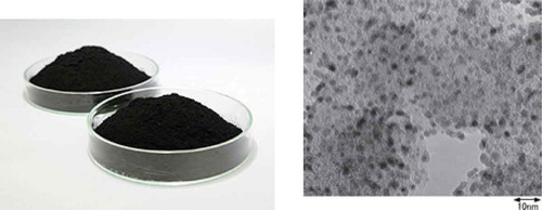
This has multiple implications. First, noble metal nanoparticles improve the kinetics of hydrogen sorption on some types of carbonCitation66,Citation67 used in hydrogenation reactions in chemical plants. Whether this will be of major importance at higher salt-cooled-reactor temperatures is not fully known. Second, the ability to put various metals on carbon may enable a carbon bed to be used to remove metallic impurities in liquid salts.
In MSRs, large quantities of noble metal fission products are generated in the salt.Citation68 These noble metals plate out everywhere including on carbon surfaces but with a preference for metal surfaces. The noble metals are a major source of decay heat and result in MSR heat exchangers having extremely high radiation levels and significant decay heat even if the molten salt is drained from the heat exchangers. Noble metal fission product removal has been a significant challenge in MSRs.
With an external carbon bed, there is the option to coat much of the carbon with nickel or another metal to create an ultrahigh metal surface area. The expectation would be that noble metal fission products would plate out efficiently onto these surfaces. If the surfaces were a material such as nickel that is highly permeable to hydrogen, the result may be a carbon that also removes tritium. This would result in a MSR primary system with much lower levels of radioactivity when the fuel salt is drained from the system. It also creates the option of recovery of noble metal fission products for commercial use. This option has been examined in the context of reprocessing SNF but has generally been considered uneconomic because of the costs of separations. In this specific system a relatively pure waste stream of noble metals is produced that may change the economics. None of these commercial carbon forms existed when the MSRE was built, and thus, none were examined at that time for either tritium or noble metal removal.
There is one last potential application of an external carbon bed: removal of fission product gases xenon and krypton. This is a more speculative option. In the design of the MSRE, efforts were undertaken to avoid uptake of xenon and krypton in the graphite moderator because they are neutron absorbers. However, some uptake of xenon and krypton was observedCitation68 in the graphite in the core. It is believed that these inert gases diffused into void spaces that do not fill with salt because of liquid surface tension. There is the option to choose carbon to maximize xenon and krypton uptake. It is unknown at this time whether efficient carbon absorbers could be developed for MSRs to simultaneously remove tritium, krypton, and xenon at reactor temperatures.
Once tritium, Xe, and Kr are recovered, there are many technologies for separation and storage at lower temperatures outside the reactor. Low-pressure Xe and Kr absorption, separation, and storage have been demonstrated on porous (activated) carbon materials at temperatures close to room temperature.Citation69 Tritium can be stored on a wide variety of materials from uranium hydride beds to carbon at low temperatures, with many more options if tritium is converted into water.
Separate but partly coupled from the choice of absorber is the choice of absorber bed, with each bed having different characteristics:
Fluidized bed: The carbon particles are mixed with the hot salt. This is the simplest but least efficient absorber bed.
Fixed bed: The carbon is fixed in a tank or cartridge, and salt flows through it. Tritium initially loads on the inlet side of the bed and then progressively loads the bed over time. Two or more fixed beds are used with one bed being regenerated while the other removes tritium. This is similar to many water ion exchange cleanup systems, and it is the simplest system.
Moving bed: In a moving bed the carbon flows countercurrent to the flowing salt. This is the most complex option but with the greatest capabilities including continuous regeneration of the carbon bed and the potential to control redox potential.
The efficacy of any of these systems for tritium removal depends upon the fraction of the salt flow sent through the absorber bed and its location. If the goal is to minimize tritium in all forms in the reactor, a full-flow carbon bed between the reactor core and heat exchangers would be used. This minimizes tritium in the system. The most capable tritium removal system is the moving bed absorber. A high-performance moving bed system is shown schematically in for removal of tritium from salt.
Fig. 8 Tritium carbon absorber bed.
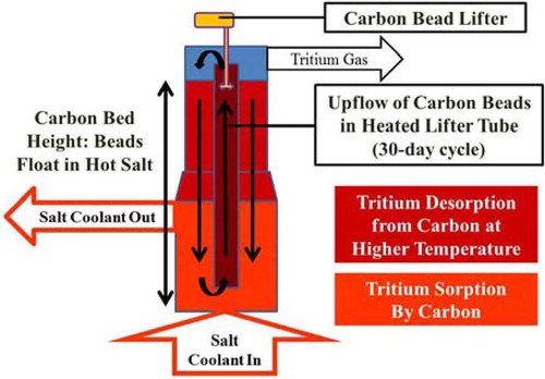
Hot salt from the reactor core enters the carbon absorber bed, and tritium is absorbed onto the carbon in a countercurrent absorber configuration. Salt flows upward while the carbon beads flow downward in the column, so the carbon with the highest tritium content contacts the salt with the highest tritium content. Fresh carbon beads with low tritium content are exposed to the salt leaving the bed with a low tritium concentration. Countercurrent flow maximizes tritium removal and tritium bed loading. The carbon beads float in the salt. While the theoretical density of graphite is higher than salt, most carbon forms have lower densities.
At the bottom of the absorber bed, the carbon beads enter an insulated and heated lifter tube that circulates the beads from the bottom to the top of the bed with the help of the carbon bead lifter. As the beads move upward and are heated, the tritium is desorbed and exits the reactor via the gas space above the top of the bed.
The carbon beads are returned to the absorber bed in a downcomer that is also heated. The temperature in the downcomer at the top matches the peak temperature in the lifter tube. Heating the carbon beads removes the tritium. There is the option of injecting an inert gas, hydrogen, or a gas mixture [H2, HF, inert gas] into the downcomer. This stripper gas would move upward in the downcomer and also exit to the off-gas system. The use of a stripper gas, depending upon the gas composition, has several functions:
Tritium removal: An inert gas will shift the equilibrium and remove added tritium from the carbon. Alternatively, if a mixture of inert gas and nonradioactive H2 is injected into the downcomer, the nonradioactive hydrogen isotopically exchanges with the residual tritium in the carbon and lowers the residual tritium content of the carbon. This nonradioactive H2 absorbed on the carbon will then exchange with tritium from the salt in the lower absorber bed lowering the residual tritium concentration in the liquid salt leaving the carbon bed. That, in turn, lowers release of tritium by diffusion through the hot heat exchangers. The hydrogen content of the carbon leaving the downcomer is determined by the carbon temperature. Higher temperatures imply less hydrogen on the carbon beds. The penalty of injecting nonradioactive hydrogen is additional hydrogen in the tritium that must be disposed of with the tritium.
Redox control: Using a mixture of H2/HF in the stripper gas may allow control of the redox potential in the FLiBe. In the MSRE the redox potential at 650°C was maintained at −700.5 KJ/mol-F2 to minimize corrosion. That redox potential could be maintained in the FHR (CitationRef. 4) if the ratio of partial pressures is
This would require a reliable capability to measure the salt redox potential online to adjust the relative amounts of hydrogen and hydrogen fluoride in the stripper gas. The H2/HF absorbed on the carbon can be controlled by the temperature in the bottom half of the downcomer.
Several experimental programs are under way to measure hydrogen behavior for tritium removal to enable design of a tritium control system. MIT (CitationRef. 70) is measuring hydrogen sorption and desorption on different nuclear and porous carbon forms at pressures near 1 Pa (FHR tritium pressure) over temperature ranges of 400°C to 1100°C. Some early results are shown in . This example shows the dramatic differences in hydrogen sorption between nuclear-grade graphite and other carbon forms that have not gone through the extreme processing to assure dimensional stability in high neutron fluxes.
Fig. 9. Preliminary hydrogen adsorption experiments on nuclear graphite ISO-88, Maxsorb MSC-30, and CalgonCarbon CAL-TR 12x40 at 700°C.
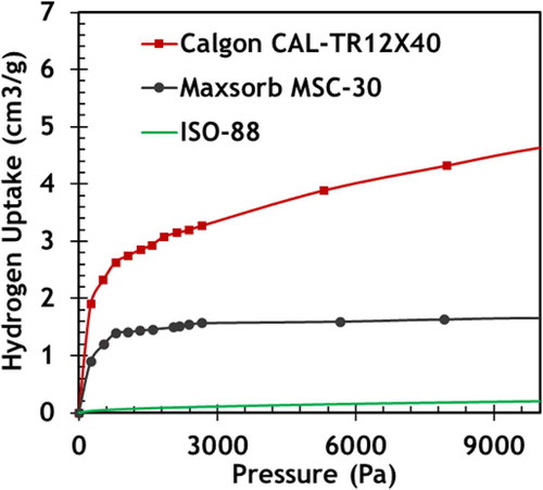
Using static and dynamic flow methods for chemisorption analysis, the adsorption capacity and relative uptake rate of hydrogen on different carbon forms are being tested. This includes high-performance activated carbons such as Maxsorb MSC-30, which demonstrated high H2 uptake at room temperature and pressure, nuclear-grade graphite IG-110U, fuel matrix graphite, and carbon-carbon composites that are proposed for ORNL's plate fuel. More recently, the development of new carbon forms such as grapheneCitation71 opens up additional classes of carbon as candidate tritium sorbers. By testing different forms of carbon that could exist in the FHR system, the performance of systems-level models can be improved.
Hydrogen and deuterium surrogates are used so that results can be extrapolated to tritium using rate theory. The emphasis is on conducting experiments over FHR operating conditions of temperatures from salt freezing at 459°C to a transient condition at 800°C and pressures of <1 Pa required to minimize release relative to the unmitigated case predicted by TRIDENT (CitationRefs. 34, Citation35, and Citation36). The primary instruments being used are a Quantachrome Autosorb IQ-C for chemisorption and a Pfeiffer Prisma Plus for mass spectrometry during temperature programmed desorption. In parallel, various microstructural characteristics are being determined through Brunauer-Emmett-Teller (BET) surface area analysis, pore size distribution, Raman spectroscopy, X-ray diffraction, and scanning electron microscopy. By understanding the effective diffusion pathways and identifying reactive hydrogen-binding sites, carbons can be selected or designed for each application.
University of Wisconsin–MadisonCitation52 is characterizing tritium transport across the salt-carbon interfaces and into the carbon. MIT (CitationRef. 60) and UW are conducting integrated tests of tritium behavior on carbon that includes irradiating various forms of carbon in 700°C salt. These programs are expected to develop the required information on carbon tritium behavior in salt to predict tritium behavior in salt-cooled reactors and design tritium removal systems. The different programs (MIT, UW, CAS, etc.) have chosen several common carbon forms for testingCitation3 to enable benchmarking of results between the different laboratories using somewhat different techniques.
There are a limited number of other possible absorbers for tritium in molecular form that are chemically compatible with high-temperature salts. These are primarily metals such as nickel. What historically sets carbon apart from all other materials is its extremely high specific surface area, which is the basis for its use as a support structure for catalysts. However, new manufacturing processes such as additive manufacturing may be able to create high-surface-area metal forms with appropriate salt flow and tritium sorption characteristics. shows an example of additive manufacturing of metal structures. The goal is a geometric form with low liquid salt flow resistance, good mass transfer of tritium to metal surface, and good structural integrity. The diffusion coefficient of tritium in salt is low; thus, mass transfer is important. Such materials can be tested with the same methods as described earlier.
Fig. 10. Additive manufacturing enables optimized structures for tritium and noble metal removal from liquid salts. Printed in Type 316L stainless steel on an SLM 280 machine using a 400-W laser. (Courtesy of SLM Solutions NA Inc.)
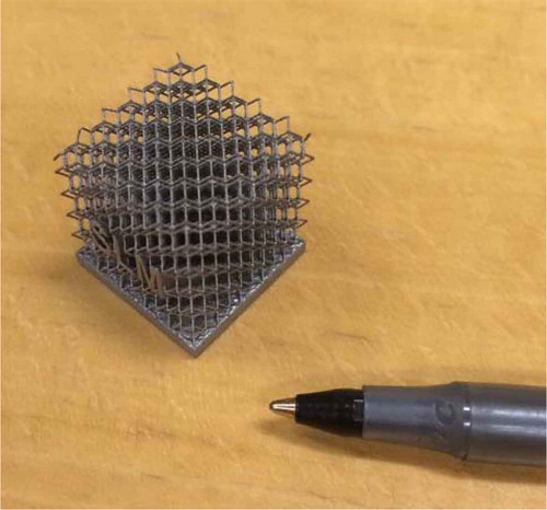
Such metal forms may greatly simplify the removal of noble metal fission products in MSRs. Such forms can be converted into low-surface-area solid waste forms by compression in a high-pressure press. This technique is currently used in reprocessing plants to convert SNF cladding and other highly radioactive metallic wastes into solid ingots.
There are limitations. A separate consideration is removal of other tritium species. Carbon will remove 3HF, but these metallic forms may be able to remove only 3H2 and noble metals. If the redox chemistry is controlled, the tritium can be forced into the form of 3H2.
IV.C. Operations
If a carbon bed is used for tritium removal and the reactor has carbon elsewhere in the system (FHR fuel and thermal-spectrum MSR moderator), tritium will be in both locations. If the carbon bed is designed to maintain very low levels of tritium in the coolant salt, there will be very low equilibrium levels of tritium elsewhere in the system. This characteristic simplifies operations because if the tritium removal system is down for any reason, the carbon elsewhere in the system will hold most of the tritium that is generated for several days until repairs can be made. It also implies low tritium inventories that could be released in an overtemperature transient event.
IV.D. Carbon and Corrosion
The presence of carbon in a salt system alters corrosion rates. Experiments at MIT and UW (CitationRef. 61) only are under way to understand the various mechanisms and testing different materials with and without carbon in the system.
V. Other Options for Tritium Removal from Salt
V.A. Gas Sparging
Tritium can be removed from high-temperature liquid salt using gas sparging where an inert gas such as helium or argon is mixed with the liquid salt, promoting the preferential transfer of tritium in different forms to the gas phase and then to the off-gas system. The primary requirement is a high gas-liquid surface area for efficient transport of tritium from the liquid to gas phase. This technology is being developed for (1) tritium and tritium fluoride removal from FHRs and (2) xenon, krypton, tritium (hydrogen and fluoride forms), and noble metals for MSRs. In the 1960s MSRE a gas purge was used to remove krypton and xenon. It was experimentally observed that the off gas contained large quantities of noble metal fission products. The noble metals are insoluble in the salt and migrated to the liquid-gas interface and then to the off-gas system. Since then, gas sparging has been the leading candidate for removal of noble metal fission products from high-temperature salts. Several different programs are developing alternative gas sparging technologies for salt cleanup.
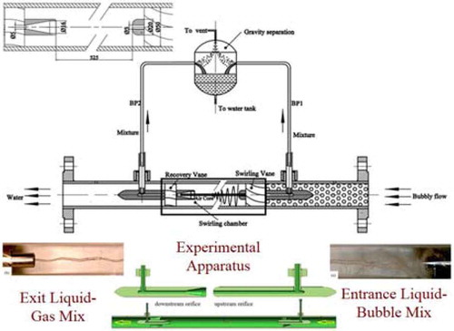
The CAS plans to build a 10-MW(thermal) FHR and a 2-MW(thermal) MSR. The CAS is developing a gas sparging systemCitation72 to remove xenon, krypton, tritium (hydrogen form and tritium fluoride), and noble metals from liquid salts. Helium will be injected into the salt with a venture-type bubble generator (0.3- to 0.5-mm bubbles) and removed with a centrifugal separator. A water version of the gas-liquid separator being used to develop the technology is shown in . The liquid with gas bubbles flows in from the right through swirling vanes to create a rod-type gas zone in the middle, the gas is removed, and the liquid flows through recovery vanes before exiting the system.
Fig. 11. Gas-liquid separator design.
In 2007 an experimental project was initiated in France to examine helium gas sparging to remove volatile fission products and noble metals from fast-spectrum MSRs (CitationRefs. 73 and Citation74). This included construction () of water models and a molten salt loop [Forced Fluoride Flow for Experimental Research (FFFER)].
Fig. 12. French sparging experiments: water loop and FLiNaK salt loop.
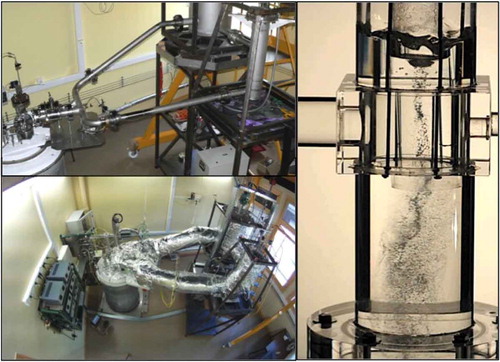
In the proposed system, the bubbles are introduced through a Venturi nozzle while a vertical column is used for liquid/gas separation. A rotating flow is induced in the vertical column separator by the tangential fluid inlet at the base. The induced centripetal forces allow separation of the bubbles from the bulk liquid flow. The process is stabilized by a fixed system inserted in the top of the column.
The experimental salt loop is operated with FLiNaK salt. This experiment also provided important experimental data/feedback on corrosion of FLiNaK salt on the stainless steel in the various loop components. These data have been used to develop static small-scale corrosion experiments. A new experimental facility is planned in the frame of the Euratom Safety Assessment of the Molten Salt Fast Reactor (SAMOFAR) to study molten salt thermal hydraulics.
The University of New Mexico (Albuquerque)Citation75,Citation76 (UNM) is initiating a program using ultrasonic gas sparging for tritium removal. Ultrasonics can potentially create smaller gas bubbles with higher surface area and thus more efficient mass transfer of tritium to the inert gas phase. In addition, bubbles entering an acoustic field can cavitate in two modes (stable and transient). In a stable cavitation mode, the bubble will oscillate with the sound field for several cycles or more of the applied wave field. During this time, the bubble may grow due to rectified diffusion where the surrounding fluid pressure is low. Upon reaching its resonance radius, the bubble will start to collapse. In transient cavitation, an oscillating bubble can collapse in one or at most only a few acoustic cycles. The actual distinction is somewhat subjective but is typically related to the resident life of the bubble relative to the period of the applied field as well as the rate of time for bubble collapse and the associated violence of the collapse. It is postulated that this sonomechanical agitation of bubbles in the process stream will enhance local mass diffusion due to the oscillation of the bubble size (see ) while also enhancing the bulk convective mass transfer occurring between the two-phase mixture due to enhanced turbulent mixing.
Fig. 13. Comparison of bubbles (a) streaming vertically in quiescent liquid and (b) being agitated within an acoustic field (the approximate acoustic field and size of the bubbles are 6 W/cm2 and 400 μm, respectively).
The CAS and UNM programs are complimentary: Ultrasonics improves mass transfer, and the CAS system improves gas-liquid separations. While ultrasonic gas dispersion has been used in a variety of systems, it has not been applied to very high-temperature systems.
As discussed in Sec. IV.B, in these systems there is also the option to include various ratios of HF to H2 in the sparging gas with the helium to control the redox of the salt. With this option the tritium in the reactor can be diluted with normal hydrogen so that much higher hydrogen release rates must occur to allow a fixed amount of tritium to escape. We are not aware of any studies to use the gas sparging system for redox control although the standard procedure to purify liquid salts is to sparge them with mixtures of H2 and HF.
There is the option of using a spray tower or equivalent system where the liquid salt is in droplets or flowing over a high-surface-area medium such as a distillation-column mesh packing and the purge gas or vacuum is the continuous medium, which is the reverse of gas sparging. It is an option originally examined by Lawrence Livermore National LaboratoryCitation77 for salt-cooled fusion machines where it was proposed that the droplets be sprayed into a vacuum tower. The engineering challenge is to provide an efficient pathway for the tritium gas to exit the tower.
The alternative to a vacuum is to have a purge gas flowing countercurrent to the gas droplets. This option may be attractive for one class of advanced MSR designs that is being developed by Hatch of CanadaCitation78 where the liquid salt flows downward through the reactor core through constrictions during normal operations to critically safe passively cooled dump tanks under the reactor core, which is a type of spray tower. The liquid salt is pumped from these tanks through the heat exchangers back to the reactor core. Any failure, including loss of power, results in the salt draining to a safe configuration.
The salt can be dispersed as droplets or flow over a metal mesh, both providing a high surface area for the liquid salt to allow the dissolved gases (tritium, xenon, and krypton) to diffuse over short distances from the liquid salt phase into the gas phase. If a high-surface-area metal mesh is used, one would expect the noble metals to plate out on the surface of the mesh, which addresses another salt cleanup challenge of MSRs. Engineered high-surface-area packings have been developed over the last 30 years for use in distillation columns and scrubbers.
V.B. Permeators
Tritium can be removed by metallic permeators. Permeators are tubes designed for high rates of hydrogen transfer through the tube where salt would be on one side of the tube and a vacuum or hydrogen getter would be on the other side of the tube to provide a large hydrogen gradient to maximize hydrogen transport. Permeators are used in the laboratory and some process operations for tritium separation and isotopic separation of different hydrogen isotopes.
Investigations are under way at The Ohio State UniversityCitation79,Citation80 (OSU) and ORNL for tritium separation in salt-cooled systems using permeators. A large part of this effort is to find ways to increase salt turbulence near the tubes to increase the rate of tritium transport from the salt to the permeator tubes. At OSU various fixed-bed and permeator optionsCitation80 for tritium removal were evaluated, and a preliminary design of a permeator for a tritium removal facility with a cross-flow configuration between the salt and carrier gas has been developed. Computational simulations have been performed to evaluate the mass transfer efficiency. A small-scale validation experiment of the proposed tritium permeator using hydrogen as a surrogate is being planned.
V.C. Double-Wall Heat Exchangers
Double-wall heat exchangers are used in the chemical industry when there are two fluids where violent reactions would occur if there was a tube failure. They have also been developed for SFRs for sodium-water heat exchangers. Such heat exchangers can be used to block tritium transport by three mechanisms: (1) vacuum between the tubes to capture tritium, (2) solid hydrogen getter between the tubes to sorb the tritium, or (3) flowing fluid such as lithium that acts as a getter. The double-wall system is both a barrier to tritium release and a collection system. The disadvantages of double-wall heat exchangers are cost and added temperature drops across the heat exchangers. ORNL, OSU (CitationRef. 81), and UNM (CitationRefs. 82 and Citation83) are investigating this tritium control and capture option for liquid salt systems.
At OSU, a natural draft heat exchanger (NDHX) is currently being designed and optimized for the direct reactor auxiliary cooling system (DRACS). In this design, DRACS secondary fluoride salt flows inside the inner tubes, and sweep gas (helium) flows in the annuli with air flowing outside the tubes. A fraction of the heat and tritium is removed by the sweep gas, and the remaining is removed by the outside air. A MATLAB code involving heat transfer and tritium mass transfer is being developed to aid the design optimization of such an NDHX.
At UNM, compact double-wall heat exchangers are being experimentally investigated for the salt power-cycle heat exchanger. These heat exchangers utilize an outer twisted tube configuration to enhance shell-side heat transfer and make the overall bundle more compact while utilizing a traditional circular inner tube to withstand high-pressure differentials across the tube wall. A combination of the tube coatings and tritium getters such as yttrium hydride is being evaluated from thermal performance and fabrication feasibility perspectives.
V.D. Power Cycles
More than 99% of the surface area in a reactor is the heat exchanger to the power cycle. The alternative to trapping tritium in the primary system is trapping it in the power cycle. Work is under way by the CAS and othersCitation84 on closed Brayton power cycles using helium or carbon dioxide. The helium closed cycles can incorporate FIRES for heat storage.
Tritium can be removed from the working gas in these power cycles. It is much easier for tritium to leak into the power cycle through hot heat exchangers than leak out of the power cycle through the much colder heat exchangers associated with the heat sink. Tritium diffusion in metals decreases rapidly with temperature. In effect, tritium tends to be trapped in closed power cycles.
VI. Tritium Barriers
There is a large literature and experience base on barriers to prevent diffusion of tritium to the environment. Better barriers reduce the requirements on the tritium removal systems in that the allowable concentrations in the salt may be higher, but they do not change the need for a tritium removal system. Without a tritium removal system, the tritium concentrations continue to increase creating a larger driving force for tritium diffusion through containment barriers. In the context of salt-cooled systems, the CAS is currently measuring permeation of hydrogen through various materials of construction and alternative methods to reduce tritium diffusion in salt-cooled reactors. The Idaho National Laboratory (INL) STAR facility for the fusion program has also had a major effort in measuring permeation rates through various materials.Citation85
In any nuclear reactor, >99% of the primary system surface area is in the heat exchangers. For efficient heat transfer these are thin metal walls relative to primary system pipes and vessels; thus, the primary concern is tritium transport through these heat exchangers to the power cycle. The choice of power cycle can have a large impact on the difficulty in containing tritium. If it is a closed helium, carbon dioxide, or steam power cycle, the tritium can be captured in the power cycle. However, in the case of steam, any leakage of tritium into the steam will result in the tritium contamination of the steam and the difficult task of separating tritium from that water.
Two specific examples of tritium barriers were identified in terms of applicability to salt-cooled reactors: one on the salt side of the heat exchangers and the other on the air side of the heat exchangers. Tritium production targets in pressurized water reactors (∼300°C) use aluminide coatingsCitation1 on the inside of Type 316 stainless steel to prevent tritium losses. This is the only high-temperature tritium barrier that we identified that is currently used on an industrial scale. Aluminide coatings are incompatible with salts.
The historical challenge with permeation barriers is that the laboratory performance has been excellent but that performance in larger systems has been much lower because of the formation of microcracks in very thin surface layers. Limited information suggests this may not be a problem for a salt-cooled reactor with NACC. The aluminide surface layers are formed by exposing the metal to hot oxidizing air, which is the environment created by the heat exchangers within NACC. Because NACC creates the environment used to make this coating, the expectation is that any cracks in the permeation layer will self-repair. Tests in large systems will be required to measure real performance.
Second, tungsten can be plated onto the inside of heat exchangers as a tritium barrier.Citation36,Citation86,Citation87 Tungsten has an extremely low solubility for hydrogen and thus is a barrier to hydrogen diffusion. Tungsten plating has been used for other applications. Tungsten is chemically compatible with liquid salts whereas most other tritium barriers are not chemically compatible with high-temperature salts.
VII. Conclusions
A confluence of events in three power technologies (FHR, MSR, and fusion) in the last several years has created the need for control and removal of tritium from high-temperature coolant salts. While there is massive experience in tritium capture and control under many different environments, that experience has not been in 700°C salt where the tritium is in the forms of 3H2 and 3HF at partial pressures of fractions of a pascal.
The current status of tritium control and capture is that limited data indicate it is feasible to maintain very low levels of tritium in a salt-cooled reactor using carbon. However, the experimental database of tritium sorption on carbon at the required conditions is small with large uncertainties. The advances in carbon technology may enable dramatic improvements in removal of tritium and other impurities from these salts. Current programs are under way to collect the experimental information needed to design tritium removal systems for salt-cooled reactors.
The status of other control technologies is somewhat behind that of capture on carbon, but experimental work is expected to provide answers in the next several years with significant efforts associated with gas sparging, partly because in a MSR, sparging is used to remove krypton and xenon.
Acknowledgments
We would like to thank the CAS, INL, ORNL, and the U.S. Department of Energy for their support and assistance. We would also like to thank V. Ghetta and R. Moir for their input.
References
- FORSBERG C. et al., Proc. Workshop Tritium Control and Capture in Salt-Cooled Fission and Fusion Reactors: Experiments, Models and Benchmarking, Salt Lake City, Utah, October 27–28, 2015, CANES ANP-165, Massachusetts Institute of Technology, Department of Nuclear Science and Engineering, Center for Advanced Nuclear Energy Systems.
- FORSBERG C. et al., “Tritium Control and Capture in Salt-Cooled Fission and Fusion Reactors,” Proc. 11th Int. Conf. Tritium Science and Technology (TRITIUM 2016), Charleston, South Carolina, April 17–22, 2016, American Nuclear Society (2016); see also Fusion Sci. Technol., 71 (2017); http://dx.doi.org/10.13182/FST16-114.
- ANDREADES C. et al., “Fluoride-Salt-Cooled High-Temperature Reactor Code Benchmarking Progress White Paper,” UCBTH-16-002, University of California, Berkeley, Department of Nuclear Engineering (June 2016); see also “FHR Code Benchmarking White Paper Series, Integrated Research Project 2, Workshop 2,” Berkeley, California, April 13–15, 2016, University of California, Berkeley.
- SERP J. et al., “The Molten Salt Reactor (MSR) in Generation IV: Overview and Perspectives,” Prog. Nucl. Energy, 77, 308 (2014); http://dx.doi.org/10.1016/j.pnucene.2014.02.014.
- FORSBERG C. WHYTE D., “Converging Fission and Fusion Systems Toward High-Temperature Liquid-Salt Coolants: Implications for Research and Development,” Proc. Int. Congress Advances in Nuclear Power Plants (ICAPP 2016), San Francisco, California, April 17–20, 2016, American Nuclear Society (2016).
- SERRANO-LOPEZ R. et al., “Molten Salts Database for Energy Applications,” Chem. Eng. Process., 73, 87 (2013); http://dx.doi.org/10.1016/j.cep.2013.07.008.
- HOLCOMB D. E. CETINER S. M., “An Overview of Liquid-Fluoride-Salt Heat Transport Systems,” ORNL/TM-2010/156, Oak Ridge National Laboratory (Sep. 2010).
- WILLIAMS D. F., “Additional Physical Property Measurements and Assessment of Salt Compositions Proposed for the Intermediate Heat Transfer Loop,” ORNL/GEN4/LTR-06-033, Oak Ridge National Laboratory (Sep. 2006).
- WILLIAMS D. F. TOTH L. M. CLARNO K. T., “Assessment of Candidate Molten Salt Coolants for the Advanced High-Temperature Reactor (AHTR),” ORNL/TM-2006/12, Oak Ridge National Laboratory (2006).
- WILLIAMS D. F., “Assessment of Candidate Molten Salt Coolants for the NGNH/NHI Heat-Transfer-Loop,” ORNL/TM-2006/69, Oak Ridge National Laboratory (June 2006).
- ROMATOSKI R. HU L. W. FORSBERG C. W., “Uncertainty Propagation of Coolant Properties in a Fluoride Salt-Cooled High Temperature Reactor,” Proc. Int. Congress Advances in Nuclear Power Plants (ICAPP 2016), San Francisco, California, April 17–20, 2016, American Nuclear Society (2016).
- FORSBERG C. PETERSON P. F., “Basis for Fluoride Salt–Cooled High-Temperature Reactors with Nuclear Air-Brayton Combined Cycles and Firebrick Resistance-Heated Energy Storage,” Nucl. Technol., 196, 13 (2016); http://dx.doi.org/10.13182/NT16-28.
- ANDREADES C. et al., “Technical Description of the ‘Mark 1' Pebble-Bed Fluoride-Salt-Cooled High-Temperature Reactor (PB-FHR) Power Plant,” UCBTH-14-002, University of California, Berkeley (Sep. 30, 2014).
- WANG D. et al., “Thermal Hydraulics Analysis of the Advanced High Temperature Reactor,” Nucl. Eng. Des., 294, 73 (2015); http://dx.doi.org/10.1016/j.nucengdes.2015.08.017.
- RICHARD J., “Design Optimization and Analysis of a Fluoride Salt Cooled High Temperature Test Reactor for Accelerated Fuels and Materials Testing and Nonproliferation and Safeguards Evaluations,” PhD Thesis, Massachusetts Institute of Technology, Department of Nuclear Science and Engineering (Sep. 2015).
- FORSBERG C. W. et al., “Development of a Fluoride-Salt-Cooled High-Temperature Reactor (FHR) Using Advanced Gas-Cooled Reactor (AGR) Technology,” Trans. Am. Nucl. Soc., 112, 566 (2015).
- GEHIN J. C. POWERS J. J., “Liquid Fuel Molten Salt Reactors for Thorium Utilization,” Nucl. Technol., 194, 152 (2016); http://dx.doi.org/10.13182/NT15-124.
- “Introduction of Thorium in the Nuclear Fuel Cycle,” NEA No. 7224, Organisation for Economic Co-operation and Development/Nuclear Energy Agency (2015).
- BURKHARDT B. et al., “Technology Assessment of an Advanced Reactor Design—A Case Study on a Molten Salt Reactor (MSR),” Proc. Int. Congress Advances in Nuclear Power Plants (ICAPP 2016), San Francisco, California, April 17–20, 2016, American Nuclear Society (2016).
- Workshop on Molten Salt Reactor Technologies: From the MSRE to a New Emerging Class of Reactors 50 Years Later, Oak Ridge, Tennessee, October 15–16, 2015, Oak Ridge National Laboratory; https://public.ornl.gov/conferences/MSR2015/pdf/AGENDA-20151014_FINAL.pdf (current as of May 25, 2016).
- SCOTT I., “Static Fuel Molten Salt Reactors Simpler, Cheaper, and Safer,” Moltex Energy; http://www.moltexenergy.com/ (current as of May 25, 2016).
- SORBOM B. N. et al., “ARC: A Compact, High-Field, Fusion Nuclear Science Facility and Demonstration Power Plant with Demountable Magnets,” Fusion Eng. Des., 100, 378 (2015); http://dx.doi.org/10.1016/j.fusengdes.2015.07.008.
- ANDREADES C. et al., “Reheat-Air Brayton Combined Cycle Power Conversion Design and Performance Under Normal Ambient Conditions,” J. Eng. Gas Turbines Power, 136, 062001 (2014); http://dx.doi.org/10.1115/1.4026506.
- ANDREADES C. DEMPSEY L. PETERSON P. F., “Reheat Air-Brayton Combined Cycle Power Conversion Off-Normal and Transient Performance,” J. Eng. Gas Turbines Power, 136, 071703 (2014); http://dx.doi.org/10.1115/1.4026612.
- ZOHURI B. McDANIEL P. J. DEOLIVEIRA C. R., “Advanced Nuclear Open Air-Brayton Cycles for Highly Efficient Power Conversion,” Nucl. Technol., 192, 48 (2015); http://dx.doi.org/10.13182/NT14-42.
- STACK D. C. et al., “Conceptual Design and Market Assessment of Firebrick Resistance Heated Energy Storage (FIRES)—Avoiding Wind and Solar Electricity Price Collapse to Improve Nuclear, Wind, and Solar Economics,” Proc. Int. Congress Advances in Nuclear Power Plants (ICAPP 2016), San Francisco, California, April 17–20, 2016, American Nuclear Society (2016).
- FORSBERG C. W. et al., “Fluoride-Salt-Cooled High-Temperature Reactor (FHR) Commercial Basis and Commercialization Strategy,” MIT-ANP-TR-153, Massachusetts Institute of Technology (Dec. 2014).
- The Future of Solar Energy, Massachusetts Institute of Technology (2015); http://energy.mit.edu/research/future-solar-energy/ (current as of Dec. 5, 2016).
- FORSBERG C., “Strategies for a Low-Carbon Electricity Grid with Full Use of Nuclear, Wind and Solar Capacity to Minimize Total Costs,” MIT-ANP-162, Massachusetts Institute of Technology, Department of Nuclear Science and Engineering ((Aug. 2015).
- MILLS A. WISER R., “Changes in the Economic Value of Variable Generation at High Penetration Levels: A Pilot Case Study of California,” LBNL-5445E, Lawrence Berkeley National Laboratory (June 2012).
- TERAI T. TANAKA S., “Tritium Release Behavior from Liquid Tritium Breeding Materials for Fusion Reactor Blanket Under Neutron Irradiation,” Prog. Nucl. Energy, 32, 1–2, 97 (1989); http://dx.doi.org/10.1016/S0149-1970(97)00010-3.
- SUZUKI A. TERAI T. TANAKA S., “Tritium Release Behavior from Li2BeF4 Molten Salt by Permeation Through Structural Materials,” Fusion Eng. Des., 51–52, 863 (2000); http://dx.doi.org/10.1016/S0920-3796(00)00233-7.
- TERAI T. SUZUKI A. TANAKA S., “In-Situ Tritium Release Experiment from Molten Li2BeF4 Salt Under Neutron Irradiation at Elevated Temperatures (INTREXFLIBE),” Fusion Technol., 30, 3 Part 2A, 911 (1996).
- STEMPIEN J. D. BALLINGER R. G. FORSBERG C. W., “An Integrated Model of Tritium Transport and Corrosion in Fluoride Salt-Cooled High-Temperature Reactors (FHRs)—Part I: Theory and Benchmarking,” Nucl. Eng. Des., 310, 258 (2016); http://dx.doi.org/10.1016/j.nucengdes.2016.10.051.
- STEMPIEN J. BALLINGER R. G. FORSBERG C. W., “An Integrated Model of Tritium Transport and Corrosion in Fluoride Salt-Cooled High-Temperature Reactors (FHRs)—Part II: Simulations in FHRs,” Nucl. Eng. Des. (submitted for publication).
- STEMPIEN J. D., “Tritium Transport, Corrosion, and Fuel Performance Modeling in a Fluoride Salt-Cooled High-Temperature Reactor (FHR),” PhD Thesis, Massachusetts Institute of Technology (June 2015).
- PETERSON H. T. BAKER D. A., “Tritium Production, Releases and Population Doses at Nuclear Power Reactors,” Fusion Technol., 8, 2544 (1985); http://dx.doi.org/10.13182/FST8-2544.
- LUSCHER W. G. et al., “In-Situ Measurement of Tritium Permeation Through Stainless Steel,” J. Nucl. Mater., 437, 373 (2013); http://dx.doi.org/10.1016/j.jnucmat.2013.02.009.
- BURCHELL T. D., “2.10 Graphite: Properties and Characteristics,” Compr. Nucl. Mater., 2, 285 (2012); http://dx.doi.org/10.1016/B978-0-08-056033-5.00020-3.
- BURCHELL T. D., “4.10 Radiation Effects in Graphite,” Compr. Nucl. Mater., 4, 299 (2012); http://dx.doi.org/10.1016/B978-0-08-056033-5.00091-4.
- KASTEN P. R. et al., “Graphite Behavior and Its Effects on MSBR Performance,” ORNL-TM-2136, Oak Ridge National Laboratory (1969).
- HE X. et al., “Protection of Nuclear Graphite Towards Liquid Fluoride Salt by Isotropic Pyrolytic Carbon Coating,” J. Nucl. Mater., 442, 306 (2013); http://dx.doi.org/10.1016/j.jnucmat.2013.09.015.
- FENG S., “Sealing Nuclear Graphite with Pyrolytic Carbon,” J. Nucl. Mater., 441, 449 (2013); http://dx.doi.org/10.1016/j.jnucmat.2013.06.035.
- TANAIKE O. INAGAKI M., “Degradation of Carbon Materials by Intercalation,” Carbon, 37, 1759 (1999); http://dx.doi.org/10.1016/S0008-6223(99)00050-0.
- CAUSEY R. A. et al., “The Retention of Deuterium and Tritium in POCO AXF-5Q Graphite,” J. Vac. Sci. Technol. A, 4, 1189 (1986); http://dx.doi.org/10.1116/1.573392.
- ATSUMI H. et al., “Absorption and Desorption of Deuterium on Graphite,” J. Nucl. Mater., 155–157, 241 (1988); http://dx.doi.org/10.1016/0022-3115(88)90247-4.
- ATSUMI H., “Mechanism of Hydrogen Trapping and Transport in Carbon Materials,” Phys. Scr. T, 103, 77 (2003); http://dx.doi.org/10.1238/Physica.Topical.103a00077.
- ATSUMI H. et al., “Thermal Desorption of Hydrogen from Carbon and Graphite at Elevated Temperatures,” J. Nucl. Mater., 438, S963 (2013); http://dx.doi.org/10.1016/j.jnucmat.2013.01.209.
- ATSUMI H., “Desorption of Hydrogen Trapped in Carbon and Graphite,” J. Nucl. Mater., 442, S746 (2013); http://dx.doi.org/10.1016/j.jnucmat.2013.03.041.
- DINO W. A., “H2 Dissociative Adsorption at the Zigzag Edges of Graphite,” Surf. Sci. Nanotech., 2, 77 (2004); http://dx.doi.org/10.1380/ejssnt.2004.77.
- MIURA Y. et al., “First Principles Studies for the Dissociative Adsorption of H2 on Graphene,” J. Appl. Phys., 93, 3395 (2003); http://dx.doi.org/10.1063/1.1555701.
- YOUNG M. et al., “Characterization of Tritium Transport in the Flibe-Graphite System, for In-Situ Tritium Absorption by the Fuel Elements of the Fluoride-Salt-Cooled High-Temperature Reactor (FHR),” Proc. 16th Int. Topl. Mtg. Nuclear Reactor Thermal Hydraulics (NURETH-16), Chicago, Illinois, August 30–September 4, 2015, American Nuclear Society (2015).
- PAPPANO P. J. et al., “A Novel Approach to Fabricate Fuel Compact for the Next Generation Nuclear Plant (NGNP),” J. Nucl. Mater., 381, 25 (2008); http://dx.doi.org/10.1016/j.jnucmat.2008.07.032.
- CONTESCU C. et al., “Practical Aspects for Characterizing Air Oxidation of Graphite,” J. Nucl. Mater., 381, 15 (2008); http://dx.doi.org/10.1016/j.jnucmat.2008.07.020.
- CONTESCU C., “Detection of Hydrogen Spillover in Palladium-Modified Activated Carbon Fibers During Hydrogen Adsorption,” J. Phys. Chem., 113, 5886 (2009).
- FORSBERG C. W. PETERSON P. F., “Spent Nuclear Fuel and Graphite Management for Salt-Cooled Reactors: Storage, Safeguards, and Repository Disposal,” Nucl. Technol., 191, 113 (2015); http://dx.doi.org/10.13182/NT14-88.
- CAUSEY R. A., “Hydrogen Diffusion and Solubility in Pyrolytic Carbon,” Carbon, 17, 323 (1979); http://dx.doi.org/10.1016/0008-6223(79)90003-4.
- ATSUMI H. TANABE T. SHIKAMA T., “Bulk Hydrogen Retention in Neutron-Irradiated Graphite at Elevated Temperatures,” J. Nucl. Mater., 390–391, 581 (2009); http://dx.doi.org/10.1016/j.jnucmat.2009.01.112.
- ATSUMI H. TANABE T. SHIKAMA T., “Hydrogen Behavior in Carbon and Graphite Before and After Neutron Irradiation—Trapping, Diffusion, and the Simulation of Bulk Retention,” J. Nucl. Mater., 417, 633 (2011); http://dx.doi.org/10.1016/j.jnucmat.2010.12.100.
- CARPENTER D. et al., “Findings of the Second Round of Fluoride Salt High Temperature Reactor Materials Irradiation Tests at the MIT Research Reactor,” Proc. 2015 Int. Conf. Advances in Nuclear Power Plants (ICAPP 2015), Nice, France, May 3–6, 2015.
- ZHENG G. et al., “The Effect of Tritium Generation on Alloys Corrosion in Molten Li2BeF4 (FLiBe) Salt,” Proc. 11th Int. Conf. Tritium Science and Technology (TRITIUM 2016), Charleston, South Carolina, April 17–22, 2016, American Nuclear Society (2016).
- ATSUMI H. TANABE T. SHIKAMA T., “Trapping State of Hydrogen Isotopes in Carbon and Graphite Investigated by Thermal Desorption Spectrometry,” Fusion Sci. Technol., 67, 245 (2015); http://dx.doi.org/10.13182/FST14-T2.
- HE L. et al., “Investigation of Morphology and Hydrogen Adsorption Capacity in Disordered Carbons,” Carbon, 80, 82 (2014); http://dx.doi.org/10.1016/j.carbon.2014.08.041.
- BHAT V. V. et al., “Atypical Hydrogen Uptake on Chemically Activated, Ultramicroporous Carbon,” Carbon, 48, 1331 (2010); http://dx.doi.org/10.1016/j.carbon.2009.12.001.
- ATSUMI H. et al., “Hydrogen Trapping in Neutron-Irradiated Graphite,” J. Nucl. Mater., 386–388, 379 (2009); http://dx.doi.org/10.1016/j.jnucmat.2008.12.135.
- BHAT V. V. et al., “Kinetic Effect of Pd Additions on the Hydrogen Uptake of Chemically-Activated Ultramicroporous Carbon,” Carbon, 48, 2361 (2010); http://dx.doi.org/10.1016/j.carbon.2010.02.025.
- BHAT V. V. et al., “The Role of Destabilization of Pallidadium Hydride in the Hydrogen Uptake of Pd-Containing Activated Carbons,” Nanotechnology, 20, 204011 (2009); http://dx.doi.org/10.1088/0957-4484/20/20/204011.
- COMPERE E. L. et al., “Fission Product Behavior in the Molten Salt Reactor Experiment,” ORNL-4865, Oak Ridge National Laboratory (Oct. 1975).
- DUBININ M. M. et al., “Pore Structure of Carbon Adsorbents and the Adsorbability of Gases and Vapors. 2. Analysis of the Results of a Study of Krypton and Xenon Adsorption,” Bull. Acad. Sci. USSR, Div. Chem. Sci., 29, 1029 (1980); http://dx.doi.org/10.1007/BF00949148.
- LAM S. et al., “Using Carbon to Remove Tritium and Other Impurities from 700°C Salt Coolants from Fission and Fusion Power,” Proc. World Conf. Carbon (Carbon 2016), State College, Pennsylvania, July 10–15, 2016.
- WANG L. STUCKERT N. R. YANG R. T., “Unique Hydrogen Adsorption Properties on Graphene,” AIChE J., 57, 2902 (2011); http://dx.doi.org/10.1002/aic.12470.
- YIN J. L. et al., “Study on the Air Core Formation of a Gas-Liquid Separator,” J. Fluids Eng., 137, 091301 (2015); http://dx.doi.org/10.1115/1.4030198.
- BOUSSIER H. et al., “The Molten Salt Reactor (MSR) in Generation IV: Overview and Perspectives,” Proc. Generation IV International Forum Symp., San Diego, California, November 14–15 2012, p. 102.
- ALLIBERT M. et al., “Chapter 7: Molten Salt Fast Reactors,” Handbook of Generation IV Nuclear Reactors, Elsevier (2016).
- RUBIO F. L. BLANDFORD E. D. BOND L., “Survey of Advanced Nuclear Technologies for Potential Applications of Sonoprocessing,” Ultrasonics, 71, 211 (2016); http://dx.doi.org/10.1016/j.ultras.2016.06.017.
- RUBIO F. BLANDFORD E. D. BOND L. J., “Summary of Sonoprocessing Applications for Nuclear Technologies and Potential Future Applications,” Trans. Am. Nucl. Soc., 111, 1068 (2014).
- MOIR R. W. et al., “Helium-Cooled Molten-Salt Fusion Breeder,” UCID-20153, Lawrence Livermore National Laboratory (Dec. 1984).
- SHAW A., “A Staged Approach to the Design of a Nuclear Reactor,” presented at Workshop: From the MSRE to a New Emerging Class of Reactors 50 Years Later, Oak Ridge, Tennessee, October 15–16, 2016.
- WU X. et al., “Computer Simulation of Tritium Removal Facility Design,” Proc. 10th Int. Topl. Mtg. Nuclear Thermal Hydraulics, Operation and Safety (NUTHOS-10), Okinawa, Japan, December 14–18, 2014.
- WU X. et al., “Conceptual Design of Tritium Removal Facility for FHRs,” Proc. 16th Int. Topl. Mtg. Nuclear Reactor Thermal Hydraulics (NURETH-16), Chicago, Illinois, August 30–September 4, 2015, p. 4935, American Nuclear Society (2015).
- RAHNEMA F. et al., “Integrated Approach to Fluoride High Temperature Reactor Technology and Licensing Challenges (FHR-IRP),” FY 2016 Q1 Quarterly Report, Georgia Institute of Technology (Jan. 2016).
- HUGHES J. BLANDFORD E. D., “Compact Double-Wall Twisted-Tube Heat Exchanger for the Fluoride Salt-Cooled High-Temperature Reactor (FHR) and Implications for In-Service Inspection,” Trans. Am. Nucl. Soc., 111, 1064 (2014).
- RUBIO F. L. WALLACE B. BLANDFORD E. D., “Analysis of Tritium Migration and Proposed Capture/Removal Methods in Fluoride Salt-Cooled High-Temperature Reactors (FHRs),” Proc. 11th Int. Conf. Tritium Science and Technology (TRITIUM 2016), Charleston, South Carolina, April 17–22, 2016, American Nuclear Society (2016).
- FORSBERG C. W. McDANIEL P., “Variable Nuclear Electricity with Base-Load Reactor, Closed Brayton Cycle and Firebrick Resistance-Heated Energy Storage,” Trans. Am. Nucl. Soc., 114, 611 (2016).
- PETTI D. A. et al., “JUPITER-II Molten Salt Flibe Research: An Update on Tritium, Mobilization and Redox Chemistry Experiments,” Fusion Eng. Des., 81, 1439 (2006); http://dx.doi.org/10.1016/j.fusengdes.2005.08.101.
- DOLAN T. J. LONGHURST G. R. GARCIA-OTERO E., “A Vacuum Disengager for Tritium Removal from HYLIFE-II Reactor Flibe,” Fusion Technol., 21, 1949 (1992); http://dx.doi.org/10.13182/FST21-1949.
- MOIR R. W. et al., “Design of a Helium-Cooled Molten-Salt Fusion Breeder,” Fusion Technol., 8, 1 Part 2A, 465 (1985).