Abstract
In clinical practice, vertebral compression fractures occur after trauma and osteoporosis. Kyphoplasty is a minimally invasive procedure using bone filler material for the treatment of such fractures. A full synthetic injectable bone substitute (SIBS) was manufactured by means of spray drying. The aim of this study was to characterize the SIBS and to analyze the remodelling process during degradation of the biomaterial and new bone formation after implantation. SIBS is an aqueous suspension of donut-like microparticles. These microparticles consist of nanocrystallites of synthetic hydroxyapatite embedded in amorphous silica gel. After implantation of SIBS in a proximal tibial diaphyseal defect in 52 rats, grafts were harvested for subsequent analysis on different days. Newly formed bone originating from endosteum was observed on day 6. Hematomas in the medullary space and cortical wounds disappeared on day 12. The wound region was completely replaced by a composite of newly formed cancellous bone, extracellular matrix, and SIBS. At day 63 the cortical defect was fully healed by bone, while newly formed bone in the medullary space almost disappeared and was replaced with bone marrow. In conclusion, SIBS demonstrated a unique structure with osteoinductive and bioresorbable properties, which induced fast bone regeneration. Therefore, a clinical application of SIBS for kyphoplasty is promising.
Introduction
Morbidity due to osteoporosis is increasing in older people. A common complication of osteoporosis is bone fracture, especially vertebral fracture.Citation1 At present, percutaneous vertebroplasty or kyphoplasty represents an effective method for treatment of vertebral fractures.Citation2 In the past, autologous bone was the first choice for treatment of bone defects, but it can be difficult to obtain sufficient amounts of autograft material. In addition, the risks of additional surgical incisions, morbidity at the donor site, and potential serious complications cannot be ignored.Citation3 Different types of bone substitutes are already used in orthopedic and plastic reconstructive surgery. Due to the development of minimally invasive surgery, implantation of synthetic injectable biomaterials is widely applied to cure osteoporotic fractures of the spine or extremities.Citation4 Such injectable bone substitutes should exhibit biocompatibility and rapid biodegradability.
Hydroxyapatite (HA), a calcium phosphate (Ca10(PO4)6(OH)2), represents the main component of bone in vertebrates. Silicon is an essential trace element that plays an active role in human bone mineralization and calcification. It has been shown that silicon is essential for the formation of connective tissue, bone mineralization, and stimulation of osteoblast proliferation.Citation5 In the last three decades, biomaterials based on hydroxyapatite and/ or silicon have been widely used in orthopedic and dental areas because of their osteoconduction capacity.Citation6 Compared with pure hydroxyapatite, silicon incorporated into hydroxyapatite increases dissolution, leading to fast bone remodelling.Citation7 Previous animal studies showed that bone tissue engineered scaffolds made from hydroxyapatite and silica are biocompatible, osteoconductive, and biodegradable. Citation8 A fully synthetic injectable bone substitute (SIBS), consisting of donut-like microparticles, was developed by our group. The majority of the particles are a few microns in diameter. Their nanostructure and composition can be described as nanocrystallites of synthetic hydroxyapatite embedded in a highly porous matrix of amorphous silica gel (mass fractions HA:SiO2 = 76:24). Amorphous silica gel is an incomplete linkage of polysilicic acid. It is characterized by numerous open bonds, which are always ≡Si—OH or ≡Si—O− groups (depending on the pH).Citation9 The open bonds and the spray-drying process produce a high specific surface area and the porosity of the particles is about 81%.
Initially, this biomaterial, NanoBone® (Artoss GmbH, Rostock, Germany), was developed as a granulate, afterwards as a form block.Citation10 Microparticles are the third application form.
The goals of the present study were to determine the physical and chemical characteristics of these microparticles and to analyze the healing process in tibial defects after implantation of SIBS by means of histology, planimetric analysis of new bone formation and biomaterial degradation, electron microscopic methods, and energy-dispersive X-ray spectroscopy (EDXS).
Materials and methods
Bone grafting substitute
All the chemicals used were specified as reagent Ph Eur grade (Sigma-Aldrich Chemie GmbH, Munich, Germany) and were used without further purification. Preparation of the full synthetic injectable bone substitute (SIBS) was done as follows. Nanocrystalline HA was produced by precipitation of diluted solutions of calcium chloride and sodium hydrogen phosphate in a special reactor at controlled temperature and pH, adjusted with ammonia solution. A molar ratio of calcium to phosphate of 1.67 was used. HA crystals produced were washed three times with deionized water followed by a triple rinsing with pure ethanol. The slip of nanocrystalline HA was mixed with pure ethanol and a silica sol to get a ratio in weight of HA:SiO2 of 76:24. The sol was obtained by hydrolysis of tetraethyl orthosilicate (TEOS) with an acid catalyst. A molar ratio of water to TEOS of 4 was used. After homogenization by means of ultrasonic treatment, the mixture was spray dried at 200°C with a Mini Spray Dryer B-290 in combination with Inert Loop B-295 (Buchi, Flawil, Switzerland). Using a two-fluid nozzle, the mixture was sprayed into fine droplets using compressed nitrogen. These were dried quickly in the drying chamber to donut-like microparticles. With a further heat treatment at 700°C in air the organic remains were removed from the biomaterial.
Characterization
The nanoporous structure of the silica gel matrix was characterized by mercury porosimetry and gas adsorption. The gas adsorption data were treated according to the Brunauer–Emmett–Teller theory (BET theory). The mercury intrusion measurements were carried out on a Pascal 440 apparatus by ThermoFinnigan (Thermo Fisher Scientific, Rochester, NY). A contact angle of 141.3° for Hg was used. The cumulative pore volume at a given pressure represents the total volume of mercury taken up by the sample at that pressure. The mean pore diameter was calculated by applying the Washburn equation and a cylindrical pore model. Nitrogen sorption measurements were performed by using a Sorptomatic 1990 apparatus by ThermoFinnigan (Thermo Fisher Scientific). All samples were degassed at 120°C before measurement for at least 24 hours at 10−5 mbar. Adsorption and desorption isotherms were measured over a range of relative pressures (p/p0) from 0 to 1.0. Surface areas were determined from the linear part of the Brunauer–Emmett–Teller equation in a relative pressure range (p/p0) of the adsorption isotherms between 0.05 and 0.25. A value of 0.162 nm2 was used for the cross-sectional area per nitrogen molecule. The total pore volume was estimated from the amount of gas adsorbed at the relative pressure p/p0 = 0.99 assuming that pores were filled subsequently with condensed adsorptive in the normal liquid state.
By means of scanning electron microscopy (SEM) images, the morphology of the microparticles was examined and the particle size distribution was determined by application of 2D image analysis software MeX® (Alicona Imaging GmbH, Graz, Austria). An SEM image with a size of 175 × 175 microns was used for diameter analysis. All particles on the SEM image were labelled manually. This was done by marking the centre and edge of each particle. Particle number and radius were collected automatically by MeX. The particle size distribution was obtained by plotting the percentage of total particles against the particle diameter. SEM images were taken with a DSM960 scanning electron microscope (Carl Zeiss, Oberkochen, Germany).
For transmission electron microscopical (TEM) imaging of the inner structure of the microparticles, the biomaterial was embedded in epoxy resin. A Leica EM UC6 microtome (Leica Gmbh, Wetzlar, Germany) equipped with a gem-grade diamond knife was used to cut ultrathin sections (typically 40–50 nm). Thin slices were prepared onto carbon coated copper grids and examined with an EM912 transmission electron microscope (Carl Zeiss). For analyzing the shape of the synthetic HA crystals by means of TEM, a droplet of an HA/ethanol suspension was placed on a perforated carbon film. In traditional bright-field imaging mode, the contrast formation, when considered classically, is formed directly by occlusion and absorption of electrons in the sample. Thicker regions of the sample or regions with a higher atomic number will appear dark, while regions with no sample in the beam path will appear bright. Scanning transmission electron microscopy (STEM) images were taken by focusing the electron beam into a narrow spot that is scanned over the sample in a raster using the same transmission electron microscope. Annular dark-field imaging is a method of mapping samples in a scanning transmission electron microscope. These images are formed by collecting scattered electrons with an annular dark-field detector.
Secondary electron STEM (STEM SE) imaging is a method of determining the topography of samples in a scanning transmission electron microscope. These images are formed by collecting secondary electrons with an SE detector.
The crystal phase of SIBS and human bone was analyzed by powder X-ray diffraction (PXRD). For X-ray diffraction measurements, the powdered samples were uniformly smeared onto a plastic sample holder using high-vacuum grease to assure a flat upper surface. X-ray diffraction patterns of the samples were determined with monochromatic Cu Kα radiation, using an Inel position-sensitive detector (Inel Inc, Stratham, NH). X-ray diffraction measurements were calibrated with silicon powder.
Animal model
The experimental protocol was approved by local animal rights protection authorities and conducted according to EU guidelines for the care and use of laboratory animals. Male Wistar rats (body weight 350–450 g; Charles River Laboratories, Sulzfeld, Germany) were used for the experiments and kept on water and standard laboratory chow, ad libitum. The rats were anesthetized with an intraperitoneal injection of 60 mg/kg of 6% sodium pentobarbital (Sigma, Deisenhofen, Germany). Anesthetized animals were placed in a supine position on a heating pad for maintenance of body temperature (36°C–37°C). After shaving an animal’s hind limb and disinfecting it, a 2 cm skin incision was made on the proximal area of the tibia to expose the tibia. A 3.5 mm diameter cortical defect was created using a dental drill (SU 100, BEGO, Bremen, Germany) under constant irrigation with 0.9% saline. These defects were filled with SIBS. The wounds were closed with absorbable sutures (Marlin, Markneukirchen, Germany). A total of 52 rats were used; animals were sacrificed on days 3, 6, 9, 12, 21, 42, and 63 after biomaterial implantation for routine histology (n = 7 animals per time point). The remaining three rats were prepared on day 9 for analysis by SEM.
Histology of tissue implants
Tibia explants were fixed in 4% phosphate-buffered formalin for 2 days and then decalcified in 20% EDTA (pH 7.2–7.4) over 2 weeks. Decalcified tissue samples were embedded in paraffin. From the median parts of paraffin-embedded tissue blocks, 3 μm thick sections were cut and stained with hematoxylin-eosin (HE) for routine histological analysis.
Histomorphometric analysis
Histomorphometry was performed on micrographs from the HE-stained sections using planimetric analysis (AxioVision, Zeiss, Jena, Germany). The images of the original defect regions were edited with Adobe Photoshop® (Adobe Systems, Mountain View, CA). The newly formed bone was marked at these images and analyzed (Analysis® software; Soft Imaging System GmbH, Muenster, Germany). The content of new bone formation was calculated as a percentage of the cortical wound and the medullary space. The number of remaining microparticles was counted as pieces per square millimeter.
Ex vivo analysis of explants by SEM and EDXS
Critical point drying (CPD) is a method of drying tissue without deforming the structure of wet, fragile specimens. Explants (n = 3) obtained after 9 days in rat tibia were prepared for SEM and EDXS analysis by critical-point drying in a CPD apparatus (K850 Critical Point Dryer, Quorum Technologies Ltd, East Grinstead, UK). For SEM analysis, the cross sections of the tibial defect area were sputter-coated with a 3 nm Au-Pd layer. Surface topography of the biomaterial was examined using an accelerating voltage of 20 kV. The local chemical composition was analyzed by EDXS using a scanning electron microscope DSM 960 (Carl Zeiss) equipped with an EDX system from SAMx (Saint Laurent Du Var, France). Cross sections of the tibial defect area were used without previous sputter-coating. To compare change of the local chemical composition, microparticles before implantation were analyzed by EDXS.
Statistical analysis
All data were uniformly distributed and therefore given as means ± standard error in the mean (sem). Analysis was performed using the software package Sigma-Stat (Jandel Corporation, San Rafael, CA).
Results
Material characterization
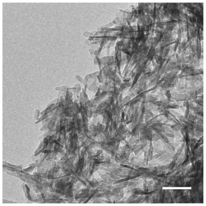
SEM images show that SIBS consists of microparticles with donut-like morphology (). The maximum particle size distribution ranges from 2–5 μm (). This particle size was necessary to prevent the microparticles’ degradation by phagocytosis. A bulk density of 0.26 g/cm3 ± 0.05 g/cm3, a specific surface area of about 168 m2/g, and a porosity of about 81% indicate SIBS as a highly porous bone graft substitute. The majority of the pores in the silica gel had sizes ranging from 10–50 nm in diameter and were interconnected (). The inner structure and composition of the microparticles was investigated by means of TEM. shows a TEM image of a thin section (40 nm) of a resin-embedded microparticle. Significantly, a hollow space in the center of the donut-like microparticle is observable. Furthermore, it was found that the microparticles were surrounded by a darker, more compact zone. This was due to the spray-drying process, during which the solvent evaporated faster than the solid could diffuse. The material density at the particle surface should therefore be higher than in the interior. shows a TEM micrograph of a thin section (40 nm) near the surface of a resin-embedded microparticle. Thin platelets of HA are represented as dark platelet-shaped objects, perpendicular to the image plane, embedded in silica gel. In , a scanning dark-field (STEM DF) image of the same region is presented. It represents the complementary image of . The position of the HA crystals is more pronounced (white platelet-shaped objects) due to stronger scattering of HA compared with the silica gel. In a STEM-SE image of the same region is presented, showing the nanoporous structure of the silica gel matrix. Pores with pore sizes ranging from 10–100 nm in diameter are observable and are interconnected. In the upper left corner of , the outer edge of the microparticle is presented. As already mentioned, the material shows a denser structure in this area caused by the spray-drying process. shows the X-ray diffraction pattern of the biomaterial, the main diffraction peaks of stoichiometric HA, and, for comparison, the diffraction pattern of human bone. The measurement proves that HA is the only crystal phase in our biomaterial. It is known that HA in human bone consists of nanocrystalline biological apatite.Citation11 Peak broadening of synthetic hydroxyapatite is similar to that of biological apatite in human bone, indicating a comparable crystal size in both samples. The shape of the crystals was analysed by TEM. shows a TEM micrograph of the synthetic HA. Thin platelets 3–4 nm thick, 20–25 nm wide, and 50–70 nm long are observable.
Figure 1 Representative electron microscopy images (A, B). SEM images show that SIBS consists of microparticles with donut-like morphology.
Note: Scale bars: A = 40 μm, B = 10 μm.
Abbreviations: SEM, scanning electron microscopy; SIBS, synthetic injectable bone substitute.
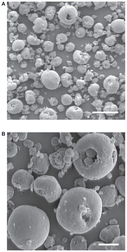
Figure 2 Quantitative analysis of particle size of the microparticles. The maximum of the particle diameter distribution from 2–5 μm is represented.
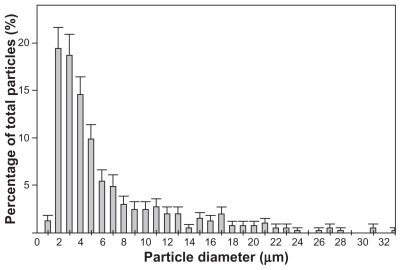
Figure 3 Distribution of pore sizes within SIBS, as measured by mercury porosimetry. The majority of the pores in the silica gel have diameters ranging from 10–50 nm.
Abbreviation: SIBS, synthetic injectable bone substitute.
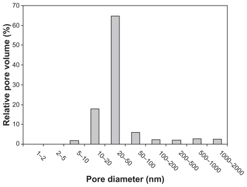
Figure 4 TEM image of a thin section (40 nm) of a resin-embedded microparticle. Significantly, a hollow space in the center of the donut-like microparticle is observable. The microparticles are surrounded by a darker more compact edge.
Note: Scale bar = 1 μm.
Abbreviation: TEM, transmission electron microscopy.
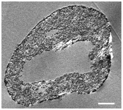
Figure 5 Representative electron microscopy images of a thin section (40 nm) near the surface of a microparticle by means of TEM (A), scanning dark-field (STEM DF, B) and scanning secondary electron (STEM SE, C) providing nanostructural aspects of SIBS. Thin platelets of HA are represented as dark platelet-shaped objects, perpendicular to the image plane, embedded in silica gel (A). A STEM DF image of the same region is presented (B). It represents the complementary image of (A). The position of the HA particles is more pronounced (white platelet-shaped objects) due to stronger scattering of HA compared with the silica gel. A STEM SE image of the same region is presented, showing the nanoporous structure of the silica gel matrix. Pores with pore sizes ranging from 10 nm to 100 nm in diameter are observable and are interconnected (C).
Note: Scale bars: A, B, and C = 100 nm.
Abbreviations: TEM, transmission electron microscopy; HA, hydroxyapatite.
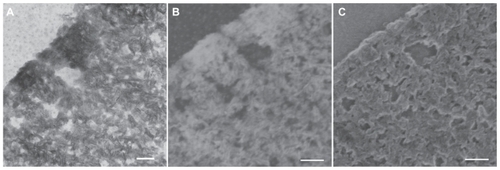
Figure 6 Representative XRD pattern of the biomaterial, the main diffraction peaks of stoichiometric HA and for comparison a diffraction pattern human bone. The measurements prove that HA is the only crystal phase in our biomaterial. The peak broadening of synthetic hydroxyapatite is similar to that of biological hydroxyapatite in human bone, indicating a comparable crystal size in both samples.
Abbreviations: XRD, X-ray diffraction; HA, hydroxyapatite.
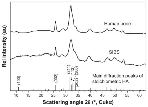
Figure 7 The shape of the crystals was analyzed by TEM. A TEM micrograph of the synthetic HA shows thin platelets of 3–4 nm thick, 20–25 nm wide, and 50–70 nm long.
Note: Scale bar = 50 nm.
Abbreviations: TEM, transmission electron microscopy; HA, hydroxyapatite.
Histomorphometric analysis
Animals showed no abnormal behaviour after implantation of bone substitutes and revealed no postoperative complications.
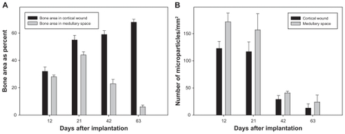
SIBS and hematoma mixture in the centre of the wound could be observed on day 3. Small blood vessels and mesenchymal cells invaded the implanted biomaterial (). New bone formation originated from endosteum on day 6. Loose connective tissue formed a scaffold with different cell types enclosing the microparticles. Some giant, multinucleated osteoclast-like cells were observed around the biomaterial and newly formed bone on day 9 (). The hematoma disappeared on day 12 and the wound region was completely replaced by newly formed cancellous bone, fibrous tissue, and biomaterials. Osteoblast-like cells were clearly observed on the surface of newly formed bone. Some osteoblasts were trapped in lacunae, thus becoming osteocytes (). Due to the histological procedures, the hematomas within the biomaterials of the tissue samples were washed away on days 3, 6, and 9. Quantification analyses of newly formed bone and degradation of SIBS were performed at day 12. The extent of newly formed bone in the medullary space was 27.8% ± 1.3% on day 12, which increased to 43.6% ± 2.4% on day 21 and stepwise decreased to 5.7% ± 1.4% until day 63 (). Conversely, new bone formation in cortical wounds increased from 32.0% ± 3.3% on day 12 to 67.8% ± 2.1% on day 63. The numbers of remaining microparticles in medullary space and cortical wound were ~172/mm2 and ~123/mm2 on day 12 after implantation. Concomitantly, a reduction was observed in final numbers to ~24/mm2 and ~13/mm2 on day 63 (). The newly formed bone and biomaterials in medullary space were almost resorbed on day 63. Repopulation with bone marrow in medullary space and lamellar bone regeneration in cortical wound indicates sufficient and almost complete bone remodelling.
Figure 8 Representative images of HE-stained specimen of the rat tibial defect. Arrows in E and F point to the implanted microparticles. A–D show histological changes over time. Asterisks indicate the newly formed cancellous (E) and lamellar (F) bone. Some giant, multinucleated osteoclast-like cells (arrowhead, E) and osteoblast layer in medullary space (arrowhead, F) are observed around the biomaterial and the new bone on day 9.
Note: Scale bars: A, B, C, and D = 500 μm, E and F = 50 μm.
Abbreviation: HE, hematoxylin-eosin.

Figure 9 Quantitative analysis of new bone formation (A, bone area as percent) and degradation (B, given as piece of square millimeter) in the cortical wound and the medullary space of HE-stained specimen at day 12, 21, 42 and 63 after microparticle implantation.
Notes: Values are means ± sem; 7 animals per group.
Abbreviations: HE, hematoxylin-eosin; sem, standard error in the mean.
Ex vivo analysis
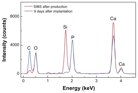
It is speculated that silica in the microparticles accelerates osteoinduction in bone defect. In support of this, quantitative analysis by means of EDXS showed that silicon disappeared and carbon increased, which further demonstrated the matrix change in SIBS over time.
In , SEM images of implanted microparticles are presented. An organic matrix formed on the surface by day 9 after implantation. The typical morphology of implanted microparticles remained unchanged at day 9 after implantation. EDXS was used to detect the in vivo change of the composition of the biomaterial (). The red curve gives the composition of SIBS after production. Therefore, the composition of silica and HA is represented. At day 9 after implantation (blue curve represents SIBS at day 9 after implantation) HA was still visible, but the silicon peak dropped substantially. These results are representative for all samples. After 9 days in vivo, nearly all silica was replaced by organic autologous material. The shape of the microparticles did not change. Therefore, this matrix change cannot be considered as resorption of the biomaterial. The resorption was carried out by osteoclasts. Silica and HA are nearly insoluble at pH 7. In water, or in simulated body fluid, a change of the composition of the biomaterial was not observed (data not shown).
Figure 10 Representative SEM images (A, B) of SIBS 9 days after implantation. Arrows point to the implanted microparticles (A).
Note: Scale bars: A = 20 μm, B = 9 μm.
Abbreviations: SEM, scanning electron microscopy; SIBS, synthetic injectable bone substitute.
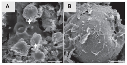
Figure 11 EDXS spectrum analysis of SIBS after production and 9 days after implantation. Silicon disappears 9 days after implantation and calcium increases, indicating a rapid matrix change with bone formation.
Abbreviation: EDXS, energy-dispersive X-ray spectroscopy.
Discussion
The present results demonstrate that a full synthetic injectable bone substitute significantly induced new bone formation after implantation in tibial defects. Furthermore, it was almost absorbed after 63 days following replacement of the medullar cavity with marrow. We have already described the early matrix change of implanted NanoBone granules into adipose neck tissue in rats.Citation10 The silica in these granules disappeared 12 days after implantation. In this study, the silica matrix of SIBS disappeared 9 days after implantation, indicating a fast matrix change. In another study, the analysis after implantation of NanoBone block materials in minipigs have also shown a replacement of the silica gel matrix by a matrix of autologous organic molecules.Citation12
Due to good clinical results, biomaterials were widely used for augmentation of osteoporotic vertebral compression fractures.Citation13 On one hand, all kinds of natural and synthetic biomaterials can be modified as bone substitutes, including gelatine, collagen, bioglass, and calcium phosphate. The choice of biomaterials as bone substitutes depends greatly on the application site, mechanical properties, osteoconduction, degradation behavior, and other factors. On the other hand, different architectural parameters of biomaterials, for example, structure, particle size, pore size, and interconnectivity, are very important for bone tissue engineering.Citation14
The synthetic nanocrystalline HA is morphologically very similar to biological apatite in bone mineral, which has been widely used in clinical practice as a bone graft substitute. A variety of in vitro and in vivo experiments showed silicon rich biomaterials were biocompatible and bioactive with osteoconductive characters.Citation15,Citation16 Previous work suggested that HA with incorporation of silicate ions significantly improved in vivo bioactivity compared with conventional HA materials.Citation17 Another study in patients demonstrated that a bone substitute comprised of nanocrystalline hydroxyapatite embedded in a silica matrix was successful in oral and maxillofacial surgery.Citation18 Based on a silica-embedded nanohydroxyapatite bone substitute, we created a novel injectable biomaterial. It can be easy implanted in irregular bone defects through minimally invasive surgical approaches. Any newly developed biomaterial should be tested for biocompatibility, potential inflammatory reaction, and safety before clinical application. The rat tibial defect model is one of the methods commonly used for the evaluation of bone substitutes. Biomaterials have the potential to induce inflammatory reactions through direct contact with bone marrow cells.Citation19 The high biocompatibility of SIBS is supported by the fact that neither leukocytes nor new formation of blood vessels surrounding the implants could be observed.
Following vascular invasion, mesenchymal stem cells of the bone marrow differentiate into osteogenic cells, including osteoblasts, which are responsible for bone formation.Citation3 It seems that SIBS activates osteoprogenitor cells very quickly, with new bone formation at day 6. Inflammatory cells, including macrophages, produce cytokines and promote the differentiation of osteoclast precursors into mature osteoclasts, which play a prominent role in bone metabolism. Citation20 Since almost all microparticles were gone 63 days after implantation, it is hypothesized that the microparticles were degraded by osteoclasts.
A previous study by our group showed that the silica gel in the bone substitute NanoBone is replaced by bone matrix glycoproteins with known functions in attraction, adhesion, and differentiation of bone cells as osteoblasts and osteoclasts by 12 days after implantation in subcutaneous tissue.Citation10 After implantation of SIBS into tibia defects, silica completely disappeared at day 9, indicating a rapid matrix change in bone regeneration. Silica has an important impact on regulation of generation, mobilization, differentiation, and activation of osteoclast precursors.Citation5 It has been established that a high silica content promotes rapid bone mineralization.Citation21 To better understand SIBS bioactivity, further studies are required to determine silica metabolic pathways. Meanwhile, practical handling characteristics should be improved to facilitate application of the materials by clinicians.
Conclusion
With its unique nanostructure and composition, SIBS exhibits some biological characters of biocompatibility, osteoconduction, osteoproduction, and degradation. This novel injectable bone substitute can be used for treatment of irregular bone fractures and difficult surgical approaches.
Acknowledgments
The authors would like to thank Anja Clasen and Holger Keuer (Department for Materials Research, Institute of Physics, University of Rostock) for excellent technical assistance. This study has been supported by a grant from the German Federal Ministry of Education and Research (BMBF 01EZ0729).
Disclosure
The authors report no conflicts of interest in this work.
References
- AsheMCKhanKMImproving the treatment of major osteoporotic fracturesCMAJ2009181524724819654191
- AnselmettiGCMutoMGuglielmiGPercutaneous vertebroplasty or kyphoplastyRadiol Clin North Am201048364164920609898
- BurchardtHThe biology of bone graft repairClin Orthop Relat Res198317428426339139
- LowKLTanSHZeinSHRoetherJaMourinoVBoccacciniARCalcium phosphate-based composites as injectable bone substitute materialsJ Biomed Mater Res B Appl Biomater201094127328620336722
- JugdaohsinghRSilicon and bone healthJ Nutr Health Aging20071129911017435952
- ChanCThompsonIRobinsonPWilsonJHenchLEvaluation of Bioglass/dextran composite as a bone graft substituteInt J Oral Maxillofac Surg2002311737711936404
- PorterAEPatelNSkepperJNBestSMBonfieldWComparison of in vivo dissolution processes in hydroxyapatite and silicon-substituted hydroxyapatite bioceramicsBiomaterials200324254609462012951004
- HenkelK-OBienengräberVLenzSGerberTComparison of a new kind of calcium phosphate formula versus conventional calciumphosphate matrices in treating bone defects – a long-term investigation in pigsKey Engineering Materials2005284–286885888
- GerberTHolzhüterGGötzWNanostructuring of biomaterials: a pathway to bone grafting substituteEur J Trauma200632132140
- XuWHolzhüterGSorgHEarly matrix change of a nanostructured bone grafting substitute in the ratJ Biomed Mater Res B Appl Biomater200991269269919572294
- PetersFSchwarzKEppleMThe structure of bone studied with synchrotron X-ray diffraction, X-ray absorption spectroscopy and thermal analysisThermochim Acta2000361131138
- KirchhoffMLenzSHenkelK-OLateral augmentation of the mandible in minipigs with a synthetic nanostructured hydroxyapatite blockJ Biomed Mater Res B Appl Biomater201196234235021210515
- ArabmotlaghMRauschmannMFiller materials for augmentation of osteoporotic vertebral fracturesOrthopade201039768769220567804
- HutmacherDWSchantzJTLamCXTanKCLimTCState of the art and future directions of scaffold-based bone engineering from a biomaterials perspectiveJ Tissue Eng Regen Med20071424526018038415
- Magallanes-PerdomoMDe AzaAHMateusAYIn vitro study of the proliferation and growth of human bone marrow cells on apatite-wollastonite-2M glass ceramicsActa Biomater201062254226320026290
- PorterAEPatelNSkepperJNEffect of sintered silicate-substituted hydroxyapatite on remodelling processes at the bone-implant interfaceBiomaterials2004253303331414980425
- PatelNBestSMBonfieldWA comparative study on the in vivo behavior of hydroxyapatite and silicon substituted hydroxyapatite granulesJ Mater Sci Mater Med200213121199120615348666
- HeinemannFMundtTBiffarRGedrangeTGoetzWA 3-year clinical and radiographic study of implants placed simultaneously with maxillary sinus floor augmentations using a new nanocrystaline hydroxyapatiteJ Physiol Pharmacol200960Suppl 8919720400800
- EidKZelicofSPeronaBPSledgeCBGlowackiJTissue reactions to particles of bone-substitute materials in intraosseous and heterotopic sites in rats: discrimination of osteoinduction, osteocompatibility, and inflammationJ Orthop Res200119596296911562148
- XingLSchwarzEMBoyceBFOsteoclast precursors, RANKL/ RANK, and immunologyImmunol Rev2005208192916313338
- BalamuruganARebeloAHLemosAFRochaJHVenturaJMFerreiraJMSuitability evaluation of sol-gel derived Si-substituted hydroxyapatite for dental and maxillofacial applications through in vitro osteoblasts responseDent Mater200824101374138018417203