Abstract
Background
Three-dimensional assembly of graphene hydrogel is rapidly attracting the interest of researchers because of its wide range of applications in energy storage, electronics, electrochemistry, and waste water treatment. Information on the use of graphene hydrogel for biological purposes is lacking, so we conducted a preliminary study to determine the suitability of graphene hydrogel as a substrate for cell growth, which could potentially be used as building blocks for biomolecules and tissue engineering applications.
Methods
A three-dimensional structure of graphene hydrogel was prepared via a simple hydrothermal method using two-dimensional large-area graphene oxide nanosheets as a precursor.
Results
The concentration and lateral size of the graphene oxide nanosheets influenced the structure of the hydrogel. With larger-area graphene oxide nanosheets, the graphene hydrogel could be formed at a lower concentration. X-ray diffraction patterns revealed that the oxide functional groups on the graphene oxide nanosheets were reduced after hydrothermal treatment. The three-dimensional graphene hydrogel matrix was used as a scaffold for proliferation of a MG63 cell line.
Conclusion
Guided filopodia protrusions of MG63 on the hydrogel were observed on the third day of cell culture, demonstrating compatibility of the graphene hydrogel structure for bioapplications.
Keywords:
Introduction
Researchers worldwide have embraced the fact that graphene, a two-dimensional sp2 hybrid of carbon atoms with a honeycomb structure, is without doubt an extraordinary substance that has been extensively investigated either on its ownCitation1–Citation3 or as a composite material.Citation4,Citation5 The intriguing mechanical, thermal, electrical, and structural properties of this material are manifested in applications such as nanocomposites, transparent conducting films, sensors, supercapacitors, nanoelectronics, batteries, photovoltaic devices, and biomedicine.Citation6–Citation10
A myriad of technologies has been introduced to fabricate graphene, including mechanical exfoliation, liquid-phase exfoliation, thermal exfoliation, electrolytic exfoliation, chemical vapor deposition, and epitaxial growth,Citation11,Citation12 but chemical oxidation continues to be the most popular method owing to its simplicity, economical feasibility, and scalability. Initially, graphite is oxidized to form graphite oxide which is then exfoliated to graphene oxide. The graphene oxide is reduced to form the graphene structure.Citation4 The basal planes and edges of the graphene oxide are functionalized with oxygenous groups, such as hydroxyl, epoxide, and carboxyl,Citation13 resulting in hydrophilicity and easing the formation of a stable colloidal solution.Citation14
Recently, a number of researchers have investigated self-assembly of two-dimensional graphene oxide into three-dimensional macrostructures. Various techniques have been employed to synthesize the three-dimensional macroscale architecture, such as easy one-step hydrothermal,Citation15 noble metal-promoted,Citation16 and divalent ion-promotedCitation17 self-assembly of graphene oxide via hydrothermal heating of a graphene oxide and DNA mixture,Citation18 mixing of graphene oxide and polyvinyl alcohol,Citation19 dispersion of graphene oxide in triblock copolymers,Citation20 and curing of graphene oxide with and without the presence of resorcinol-formaldehyde suspension.Citation21 The resulting three-dimensional graphene macroassembly has high mechanical strength, high thermal stability, a high surface area, high water content, good electrical conductivity, good electrochemical performance, good dye-loading capacity, and self-healing properties.
There has been a burgeoning of biocompatibility investigations on graphene-based films in recent years, for example, a A549 mammalian cell line on graphene and graphene oxide paper,Citation22 NIH-3T3 mouse fibroblast cells on graphene-carbon nanotubes,Citation23 L929 mouse fibroblast cells on graphene- and graphene oxide-polyaniline,Citation24 graphene-reinforced chitosan,Citation25 ARPE-19 retinal pigment epithelium cells on graphene oxide-glucose oxidase,Citation26 A549 human lung carcinoma epithelial cells on graphene oxide,Citation27 nanoreduced graphene oxide functionalized noncovalently by amphiphilic PEGylated polymer chains, and nanographene oxide covalently PEGylated on U87MG human glioblastoma and MCF-7 human breast cancer cell lines.Citation28
In this work, the synthesis of graphene hydrogel using the hydrothermal processing route is reported. Graphene hydrogel was synthesized using large-area graphene oxide as a precursor at various concentrations, and was characterized using field emission scanning electron microscopy, x-ray diffractometry, and Fourier transform infrared spectroscopy. Because there is still a knowledge gap regarding the viability of cells on graphene hydrogel, we carried out in vitro cell culture on the synthesized hydrogel using a MG63 cell line for the first time.
Materials and methods
Materials
Graphite flakes were purchased from Asbury Graphite Mills, Inc (Asbury, N J). Sulfuric acid (H2SO4, 98%), potassium permanganate (KMnO4, 99.9%), hydrogen peroxide (H2O2, 30%), glutaral-dehyde (25% aqueous solution), cacodylic acid, and sodium salt trihydrate were purchased from Merck (Darmstadt, Germany). The MG63 cell line was purchased from the American Type Culture Collection (Manassas, VA). Minimum essential medium, penicillin/streptomycin and fetal bovine serum were purchased from Gibco (Grand Island, NY). MTT assay (3-(4,5-dimethylthiazol- 2-yl)-2,5-diphenyltetrazolium bromide) was purchased from Gibco (Eugene, OR). Hydrogen chloride (HCl, 37%), sodium pyruvate, hexamethyldisilazane, and dimethyl sulfoxide were purchased from Sigma-Aldrich (St Louis, MO). Phosphate buffer solution was prepared from NaCl, KCl, Na2HPO4·2H2O, and KH2PO4, which were purchased from Sigma-Aldrich. Denatured ethanol (99.7% v/v) was purchased from R and M Chemicals (Essex, UK).
Graphene oxide synthesis
Graphene oxide was synthesized from graphite using a simplified Hummers’ method.Citation29 Graphite oxide was obtained by oxidation of 3 g of graphite flakes with 400 mL of H2SO4, and 18 g of KMnO4. The mixing process, using a magnetic stirrer, took less than 5 minutes to complete. However, to ensure complete oxidation of the graphite, the mixture was stirred for three days. During oxidation, the color of the mixture changed from dark purplish-green to dark brown. To stop the oxidation process, H2O2 solution was added and the color of the mixture changed to bright yellow, indicating a high oxidation level of graphite. The graphite oxide formed was washed three times with 1 M of aqueous HCl solution and repeatedly with deionized water until a pH of 4–5 was achieved. The washing process was carried out using a simple decantation of the supernatant with a centrifugation technique. During the washing process with deionized water, the graphite oxide underwent exfoliation, which resulted in thickening of the graphene oxide solution, forming graphene oxide gel which was freeze-dried to obtain the graphene oxide solid.
Fabrication of graphene hydrogel
Graphene hydrogel was fabricated according to the method described by Xu et al with some modifications.Citation15 Ten milliliters of homogeneous graphene oxide aqueous dispersion at a concentration of 2 mg/mL, was sealed in a 16 mL Teflon-lined autoclave and maintained at 180°C for 44 hours. The autoclave was allowed to cool to room temperature, and the fabricated graphene hydrogel was removed using tweezers and the surface adsorbed water was removed with filter paper. This sample was labeled graphene hydrogel (HG)-2. Graphene hydrogels at concentrations of 1.0, 0.5, and 0.1 mg/mL were also prepared using the same procedure, and were denoted as graphene HG-1, graphene HG-0.5, and graphene HG-0.1, respectively. To investigate the effect of the lateral dimension of graphene oxide, graphene oxide solution at a concentration at 2 mg/mL was sonicated for 1 hour before being processed using the procedure described above. This sample was labeled as graphene HGS-2.
Characterization of graphene hydrogel
Measurement of the surface area of graphene hydrogel was done using a Micromeritics ASAP 2010 physisorption analyzer. The sample was placed into a sample tube, connected to the analyzer, and evacuated. Nitrogen BET surface area was calculated automatically by the system software. Field emission scanning electron microscopy images were obtained on a FEI Nova NanoSEM 400 operated at 10.0 kV. The crystalline phase was determined using a Phillips x-ray diffractometer employing a scanning rate of 0.033 degrees per second in a 2θ range from 5° to 80° with Cu Kα radiation (λ = 1.5418 Ǻ). Chemical bonding was analyzed using a Perkin Elmer Fourier transform infrared spectroscope. The spectra (% transmittance with wave number) were recorded.
Cell culture
The graphene HG-2 sample was cut and placed into a 24-well plate. Each graphene hydrogel sample was seeded with 30,000 MG63 cells per well. Cells seeded directly on the 24-well plate served as the control. Prior to cell seeding on scaffolds, a cell count was performed using a Haemacytometer (Hirschmann Laborgerate), and 500 μL media with 10% heat-inactivated fetal bovine serum was added to each well for cell proliferation. MG63 cells were maintained using minimum essential medium supplemented with 10% heat-inactivated fetal bovine serum, 1% penicillin/streptomycin, and 1 mM sodium pyruvate at 37°C in a humidified 5% CO2 atmosphere. Graphene hydrogel was incubated with the cells for one, three, five, and seven days. The media were changed every three days.
MTT assay
MTT assay was used to determine the proliferation rate of MG63 on the graphene HG-2 scaffold. After each incubation period, MTT solution of 50 μL was added to each well and left for 4 hours for a cell response to take place. This was followed by addition of 500 μL of dimethyl sulfoxide to dissolve the purple crystals reduced by the living cells. The optical density, at 570 nm, of 200 μL of the resulting solution was measured using a spectrophotometer (Varioskan Flash, Finland).
Cell morphology
Seeding by 30,000 MG63 cells was carried out on graphene hydrogel for morphological observation. Cells incubated on graphene hydrogel for days 1, 3, 5, and 7 were examined using field emission scanning electron microscopy. Prior to viewing by field emission scanning electron microscopy, cells growing on the graphene hydrogel were washed with phosphate-buffered saline, and fixed with 4% of glutaral-dehyde for 30 minutes at 4°C. Subsequently, the graphene hydrogel containing the cells was dehydrated through a series of graded alcohols and dried with hexamethyldisilazane at room temperature. The graphene hydrogel were then ready for observation by field emission scanning electron microscopy.
Statistical analysis
All experiments were performed nine times each. The results were given as means ± standard error. Statistical analysis was performed using one-way analysis of variance and Tukey test with significance reported when P < 0.001.
Results and discussion
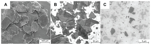
A simplified Hummers’ method was used to produce large-area graphene oxide nanosheets. The large lateral dimension graphite flakes, which were used to produce the large-area graphene oxide, are shown in , and the resulting graphene oxide is shown in . The large graphene oxide has an average area of 7000 μm2 and a lateral dimension of up to 150 μm. After being sonicated for 1 hour, the average area is significantly reduced and the lateral dimension is reduced to <5 μm, as shown in .
Figure 1 Field emission scanning electron microscopy images of (A) graphite flakes, (B) large area graphene oxide sheets, and (C) sonicated graphene oxide sheets.
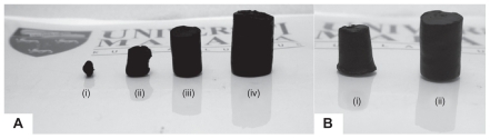
To prepare graphene hydrogel, graphene oxide underwent hydrothermal treatment at 180°C for 24 hours. The physical appearance of the prepared graphene hydrogel is shown in , with graphene hydrogel prepared at a concentration of 2 mg/mL of graphene oxide, illustrating the largest cylindrical shape with an approximate diameter of 15 mm and height of 30 mm. The surface area of graphene HG-2 was 202.4 ± 2.9 m2/g compared with the surface area of graphite of approximately 10 m2/g.Citation30 As expected, the size of graphene hydrogel was smaller when the concentration of the graphene oxide was reduced. Graphene hydrogel was produced at a concentration as low as 0.5 mg/mL. Previously reported results demonstrated precipitation at these low concentration levels.Citation15,Citation31 This can be explained by the large-area graphene oxide used in this experiment. It was found that graphene oxide concentration was not the only factor affecting the size of graphene hydrogel; it was also affected by the dimension of the graphene oxide used. The graphene hydrogel formed using graphene oxide that had been sonicated for 1 hour (with a lateral dimension of <5 μm) has a smaller size compared with the nonsonicated graphene oxide, even though the initial concentration of graphene oxide in both the syntheses was 2 mg/mL, as shown in .
Figure 2 Photographs of (A) graphene HG-0.1 (i), graphene HG-0.5 (ii), graphene HG-1 (iii) and graphene HG-2 (iv), and (B) comparison of graphene HGS-2 (i) and graphene HG-2 (ii).
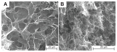
Field emission scanning electron microscopy images of the samples have well defined and interlinked three-dimensional graphene sheets forming a porous network that resembles a loose sponge-like structure, as shown in . The pore walls are made up of thin layers of graphene sheets. The supercritical condition resulted in the graphene oxide sheets converging, overlapping, and coalescing to form cross-links, which give rise to the framework of the graphene hydrogel. The mobility of the large graphene oxide sheets in solution is strongly limited, causing these graphene oxide sheets to orientate randomly in a hydrogel. Moreover, the large conjugated basal planes make the graphene oxide sheets stiff and able to form a stable network.Citation32 The pore size of the graphene hydrogels produced from large area graphene oxide is relatively independent of the concentration of graphene oxide over the measured concentration range (0.5–2 mg/mL). In contrast, graphene HG-2, which was produced from the small-area graphene oxide, has a much smaller pore size than that of graphene HG-2. A plausible explanation for the well-defined large pore size leading to the well-formed cylindrical structure of graphene HG-2 is that the high concentration of large graphene oxide restricts the expansion and flexibility of graphene oxide sheets within the geometry of the autoclave, which is crucial in constructing the three-dimensional microstructure.Citation15 On the other hand, prolonged sonication for 1 hour shattered the graphene oxide sheets (see ) which resulted in a much smaller pore size and much finer pore walls in the network of graphene HGS-2, resulting in the malformed cylindrical shape. Therefore, the pore size of the network is dependent on the lateral size of the graphene oxide nanosheets.
Figure 3 Field emission scanning electron microscopy images of (A) graphene HG-2 and (B) graphene HGS-2.
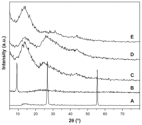
X-ray diffraction patterns for graphene hydrogel are shown in . The diffraction peaks are 26.5° for pristine graphite, 9.1° for graphene oxide, 13.5° for graphene HG-0.5, 13.7° for graphene HG-2, and 13.3° for graphene HGS-2, corresponding to a layer-to-layer distance of 3.36 Ǻ, 9.68 Ǻ, 6.55 Ǻ, 6.45 Ǻ, and 6.64 Ǻ, respectively. The interlayer distance for graphene oxide is significantly larger than for pristine graphite due to the intercalating oxide functional groups.Citation33 The interlayer distance for graphene hydrogel is lower compared with graphene oxide, indicating removal of the oxide functional groups from the graphene sheets after the hydrothermal process. Meanwhile, the appearance of a characteristic peak of graphite for nonsonicated graphene hydrogel, which shifted slightly to the left, suggests the existence of π–π stacking between graphene sheets due to the recovery of a π-conjugated system from the graphene oxide nanosheets upon hydrothermal reduction. Their interlayer spacing was slightly higher than for graphite, which is 3.63 Ǻ and 3.39 Ǻ, respectively, for graphene HG-0.5 and graphene HG-2. The diffraction peak and interlayer distance of graphene HG-2 is the closest to that of graphite because of its relatively high concentration. The characteristic graphite diffraction peak is missing from the graphene HGS-2 sample. This can be explained by the small lateral size of the graphene nanosheets, as shown by a small pore size and cotton-like appearance in field emission scanning electron microscopy (). Although some layering is likely to be present due to self-assembly of the graphene oxide nanosheets through van der Waals forces and hydrogen bond interactions, the graphene is disordered enough not to produce the signature π–π stacking diffraction peak.Citation21 The broad peaks of all the graphene hydrogel are indicative of poor ordering of graphene sheets along their stacking direction, which reflects that the three-dimensional structure is made up of a low degree of interlayer separation that mimics graphite.
Figure 4 X-ray diffraction patterns of (A) graphite flakes, (B) graphene oxide nanosheets, (C) graphene HG-0.5, (D) graphene HG-2, and (E) graphene HGS-2.
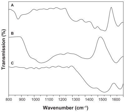
To verify the formation of graphene oxide and graphene hydrogel, the infrared spectra of the samples were measured and are compared in with the spectrum taken from graphite. In the infrared spectrum for graphite (), a peak occurs at approximately 860 cm−1 and is attributed to the aromatic C–H bonds.Citation34 The trough-like absorption peaks located between 1240 and 1590 cm−1 are associated with the stretching vibrations of both double and single C–C bonds and the stretching of C–H bonds,Citation24 whilst the peak centered at 1600 cm−1 is assigned to skeletal vibrations of unoxidized graphitic domains.Citation35 For graphene oxide, as shown in , the characteristic vibrations include the appearance of the broad peak from 900 to 1200 cm−1 attributed to C–O stretching, a C–O–C peak at 1246 cm−1, and a C–OH peak at 1400 cm−1.Citation34 The disappearance of the peaks between 1440 cm−1 and 1590 cm−1 shows that the C=C bonds have been oxidized during the chemical oxidation process. Graphene oxide exhibits a similar peak to that of graphite at 1620 cm−1, signifying nonexfoliated graphite. On the other hand, graphene hydrogel regained most of the graphitic features as illustrated in , indicating the reduction of graphene oxide during the hydrothermal process.
Figure 5 Fourier transform infrared spectra of (A) graphite flakes, (B) graphene oxide, and (C) graphene hydrogel.
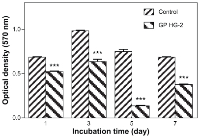
Cell proliferation on the surface of graphene hydrogel was studied using an MTT assay analysis. illustrates cell proliferation on graphene HG-2 after a culture period of 1, 3, 5, and 7 days and by measuring the optical density at a wave-length of 570 nm. On the first day of culture, cell proliferation was observed on the graphene hydrogel. The biocompatible graphene hydrogel could potentially stimulate interaction between cells and the material, which may result in an ideal condition for cell adhesion and regeneration. By increasing the culture time to 3 days, the cells continued to flourish on the hydrogel, although there was a drop in the proliferation rate. This could be due to the formation of confluent cellular layers on the surface that lowered the growth rate of cells.Citation36 However, there was a tremendous decrease in cell proliferation on the fifth day, although there was an increase in cell proliferation rate on the seventh day. Similarly, a decrease in cell viability was also observed by Robinson’s group after 2 days of treatment with nanoreduced graphene oxideCitation28 and Chang’s work after 1 day of graphene oxide exposure, as a result of oxidative stress.Citation27
Figure 6 Optical density measurement of cell proliferation on graphene HG-2 and control after 1, 3, 5, and 7 days of culture time (P < 0.001, n = 3).
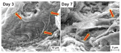
The MTT results are in good agreement with the observation of cell anchorage on the surface of graphene hydrogel. shows the field emission scanning electron microscopy results for graphene HG-2, and when compared with the original field emission scanning electron microscopy image of the original surface, the cell adherence, spreading, and growth on the surface of the hydrogel after 7 days of culture time is apparent. The images display extensive flaky layers of adhered cells with rough cellular surfaces even from the early stage of day 1, when the hydrogel was entirely covered with cells. The confluent layer appeared to be thicker after 3 days. At higher magnifications, graphene hydrogel demonstrated pronounced cell attachment where cells with flattened morphology were seen to adhere to each other, with cellular microextensions on the third and seventh days of culture as illustrated in , which is similar to the observation of Bodhak et al.Citation36 Guided filopodia protrusions, as indicated by the arrows in , were probably caused by the enhanced cell adhesion of MG63 on graphene hydrogel.Citation37 Additionally, the morphology of the spreading MG63 cells suggests their high adaptation to the as-prepared graphene hydrogel substrate. Park et al demonstrated similar cell morphologies in their in vitro study, which involved the culture of MC3T3-El on a highly organized ZnO nanoflower array.Citation38
Figure 7 Field emission scanning electron microscopy images of the cells grown on graphene HG-2 after culturing for 1, 3, 5, and 7 days. All the images share the same scale bar.
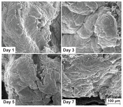
Figure 8 Guided filopodia protrusions of MG63 on graphene HG-2 after 3 and 7 days of culture time observed at higher magnifications.
Conclusion
We successfully prepared noncollapsible cylindrical three-dimensional graphene hydrogels using hydrothermal treatment of large-area graphene oxide. The cylindrical-shaped matrix was found to be a compatible host for cells as cellular microextensions pervaded the hydrogel scaffold. The proliferation of MG63 on the hydrogel was found to be time-dependent, with a reduction in viability on the fifth day of culture. Even though the cell proliferation rate decreased on the fifth day of cell culture, the rate increased on the seventh day. These aspects warrant further studies of the biocompatibility and toxicity of cells via in vitro evaluation, because the results indicated cell proliferation on the hydrogel for up to 7 days. Graphene hydrogel may be a promising building block for development of smart materials for biomolecules and tissue engineering purposes.
Acknowledgment
This work was supported by High Impact Research Grants (UM.C/625/1/HIR/030 and UM.C/625/1/HIR/MOHE/05) from the University of Malaya.
Disclosure
The authors report no conflicts of interest in this work.
References
- GeimAKGraphene: Status and prospectsScience20093241530153419541989
- GeimAKNovoselovKSThe rise of grapheneNat Mater2007618319117330084
- NovoselovKSGeimAKMorozovSVElectric field effect in atomically thin carbon filmsScience200430666666915499015
- ChoiKSLiuFChoiJSSeoTSFabrication of free-standing multilayered graphene and poly(3,4-ethylenedioxythiophene) composite films with enhanced conductive and mechanical propertiesLangmuir201026129021290820617852
- RafieeMARafieeJWangZSongHYuZKoratkarNEnhanced mechanical properties of nanocomposites at low graphene contentACS Nano200933884389019957928
- LiangJXuYSuiDFlexible, magnetic, and electrically conductive graphene/Fe3O4 paper and its application for magnetic-controlled switchesJ Phys Chem C20101141746517471
- ParkSMohantyNSukJWBiocompatible, robust freestanding paper composed of a Tween/graphene compositeAdv Mater2010221736174020496406
- FengLLiuZGraphene in biomedicine: Opportunities and challenges in nanomedicineNanomedicine2011631732421385134
- LiWZWangJLiJLinYGraphene and graphene oxide: Biofunctionalization and applications in biotechnologyTrends Biotechnol20112920521221397350
- MohantyNBerryVGraphene-based single-bacterium resolution biodevice and DNA transistor: Interfacing graphene derivatives with nanoscale and microscale biocomponentsNano Lett200884469447619367973
- ChoiWLahiriISeelaboyinaRKangYSSynthesis of graphene and its applications: A reviewCrit Rev Solid State Mater Sci2008355271
- KimHAbdalaAAMacoskoCWGraphene/polymer nanocompositesMacromolecules20104365156530
- ZhaoXZhangQHaoYLiYFangYChenDAlternate multilayer films of poly(vinyl alcohol) and exfoliated graphene oxide fabricated via a facial layer-by-layer assemblyMacromolecules20104394119416
- VadukumpullySPaulJMahantaNValiyaveettilSFlexible conductive graphene/poly(vinyl chloride) composite thin films with high mechanical strength and thermal stabilityCarbon201149198205
- XuYShengKLiCShiGSelf-assembled graphene hydrogel via a one-step hydrothermal processACS Nano201044324433020590149
- TangZHShenSLZhuangJWangXNoble-metal-promoted three-dimensional macroassembly of single-layered graphene oxideAngew Chem Int Ed20104946034607
- JiangXMaYLiJFanQHuangWSelf-assembly of reduced graphene oxide into three-dimensional architecture by divalent ion linkageJ Phys Chem C20101142246222465
- XuYWuQSunYBaiHShiGThree-dimensional self-assembly of graphene oxide and DNA into multifunctional hydrogelsACS Nano201047358736221080682
- BaiHLiCWangXShiGNon-covalent functionalization of graphene sheets by sulfonated polyanilineChem Commun (Camb)2010462376237820309457
- ZuSZHanBHAqueous dispersion of graphene sheets stabilized by pluronic copolymers: formation of supramolecular hydrogelJ Phys Chem C20091131365113657
- WorsleyMAOlsonTYLeeJRIHigh surface area, sp2- cross- linked three-dimensional graphene monolithsJ Phys Chem Lett20112921925
- HuWPengCLuoWGraphene-based antibacterial paperACS Nano201044317432320593851
- RyooSRKimYKKimMHMinDHBehaviors of NIH-3T3 fibroblasts on graphene/carbon nanotubes: Proliferation, focal adhesion, and gene transfection studiesACS Nano201046587659820979372
- YanXChenJYangJXueQMielePFabrication of free-standing, electrochemically active, and biocompatible graphene oxide-polyaniline and graphene-polyaniline hybrid papersACS Appl Mater Interfaces201022521252920735069
- FanHWangLZhaoKFabrication, mechanical properties, and biocompatibility of graphene-reinforced chitosan compositesBiomacromolecules2010112345235120687549
- LiuYYuDZengCMiaoZDaiLBiocompatible graphene oxide-based glucose biosensorsLangmuir2011266158616020349968
- ChangYYangSTLiuJHIn vitro toxicity evaluation of graphene oxide on A549 cellsToxicol Lett201120020121021130147
- RobinsonJTTabakmanSMLiangYUltrasmall reduced graphene oxide with high near-infrared absorbance for photothermal therapyJ Am Chem Soc20111336825683121476500
- HummersWSOffemanREPreparation of graphitic oxideJ Am Chem Soc1958801339
- PumeraMImaging of oxygen-containing groups on walls of carbon nanotubesChem Asian J2009425025319006131
- ZhouYBaoQLTangLALZhongYLLohKPHydrothermal dehydration for the “green” reduction of exfoliated graphene oxide to graphene and demonstration of tunable optical limiting propertiesChem Mater20092129502956
- BaiHLiCWangXShiGOn the gelation of graphene oxideJ Phys Chem C201111555455551
- LerfABuchsteinerAPieperJHydration behavior and dynamics of water molecules in graphite oxideJ Phys Chem Solids20066711061110
- SiYCSamulskiETSynthesis of water soluble grapheneNano Lett200881679168218498200
- StankovichSDikinDAPinerRDSynthesis of graphene-based nanosheets via chemical reduction of exfoliated graphite oxideCarbon20074515581565
- BodhakSBoseSBandyopadhyayABone cell-material interactions on metal-ion doped polarized hydroxyapatiteMater Sci Eng C201131755761
- MellorHThe role of formins in filopodia formationBiochim Biophys Acta2010180319120019171166
- ParkJKKimYJYeomJThe topography effect of zinc oxide nanoflowers on osteoblast growth and osseointegrationAdv Mater2010224857486120830716