Abstract
Background
This study examined the effects of electrically conductive materials made from electrospun single- or multiwalled carbon nanotubes with polyurethane to promote myoblast differentiation into myotubes in the presence and absence of electrical stimulation.
Methods and results
After electrical stimulation, the number of multinucleated myotubes on the electrospun polyurethane carbon nanotube scaffolds was significantly larger than that on nonconductive electrospun polyurethane scaffolds (5% and 10% w/v polyurethane). In the absence of electrical stimulation, myoblasts also differentiated on the electrospun polyurethane carbon nanotube scaffolds, as evidenced by expression of Myf-5 and myosin heavy chains. The myotube number and length were significantly greater on the electrospun carbon nanotubes with 10% w/v polyurethane than on those with 5% w/v polyurethane. The results suggest that, in the absence of electrical stimulation, skeletal myotube formation is dependent on the morphology of the electrospun scaffolds, while with electrical stimulation it is dependent on the electrical conductivity of the scaffolds.
Conclusion
This study indicates that electrospun polyurethane carbon nanotubes can be used to modulate skeletal myotube formation with or without application of electrical stimulation.
Introduction
Loss of skeletal muscle function can cause a noticeable decline in quality of life. There are few treatment options to replace significant muscle tissue voids. With the advent of tissue engineering and regenerative medicine, there is the potential to grow suitable skeletal muscle tissue to replace muscle loss. Earlier work of others has shown that mature tissue-engineered skeletal muscle can provide adequate support for the rigorous demands of the myocardium better than injection of myoblasts alone.Citation1 However, there is a continued need to improve the quality of engineered skeletal muscle.
Skeletal muscle tissue consists of striated nanoscale fibrous morphologies assembled into fiber bundles which contract upon stimulation by an associated nerve. When designing scaffolds for engineered skeletal muscle, mimicking the features of a natural extracellular matrix in a biomaterial scaffold can be potentially advantageous for tissue development and regeneration. For example, electrospinning has been used widely to create submicron scaffolds that resemble the physical structure of native collagen fibrils or extracellular matrix.Citation2–Citation4 Using this technique, control of chemical composition,Citation5 topography,Citation6 stiffness,Citation7 and hydrophilicity/hydrophobicityCitation8 has been shown to control cellular behavior, such as adhesion, spreading, migration, proliferation, and differentiation.Citation9,Citation10
Electrically conducting materials have also been used to deliver electrical signals to cells and to alter key cell behaviors. Electrically conductive materials, such as polypyrrole,Citation11,Citation12 polyaniline,Citation13 and poly(3,4-ethylenedioxythiophene),Citation14 have been shown to affect cell behavior when electrically stimulated. In addition, nanocomposites of polylactic acid and multiwalled carbon nanotubes (MWNT) have been reported to promote osteoblast differentiation in vitro, achieving a 46% increase in calcium deposition in the extracellular matrix and a 300% greater expression of various genes (such as osteopontin, osteonectin mRNA, and osteocalcin) when an alternating current (10 μA at 10 Hz of electrical stimulation for six hours daily for 21 consecutive days) was applied to the polylactic acid-MWNT composites.Citation15 When carbon nanotubes are incorporated into a polymer matrix, they have shown excellent compatibility with various cell types, including myoblasts,Citation16 osteoblasts,Citation17 smooth muscle cells,Citation18 endothelial cells,Citation19 and neurons.Citation20–Citation22 Abarrategi et al developed biocompatible and biodegradable scaffolds from nanocomposites of MWNT (up to 89 wt%) and chitosan to regulate C2C12 myoblast differentiation toward an osteoblast lineage in the presence of recombinant bone morphogenetic protein-2 both in vitro and in vivo.Citation16 However, augmentation of myoblast differentiation to form multinucleated myofibers on electrospun composite carbon nanotube scaffolds in the presence and absence of electrical stimulation has not yet been investigated.
We hypothesized that composite carbon nanotube materials could enhance myotube formation. The present study had two aims. One was to prepare and characterize an electrically conductive elastomer. To accomplish this, we blended single-walled carbon nanotubes (SWNT) or MWNT into medical grade polyurethane and then electrospun the composite material. The second objective was to determine the effects of myotube formation with and without electrical stimulation on this material, to provide greater insight into material design for skeletal muscle tissue engineering.
Materials and methods
Electrospinning polyurethane carbon nanotube scaffolds
A medical grade aliphatic polycarbonate-based thermoplastic polyurethane elastomer (Carbothane® PC-3585A) was obtained from Lubrizol Advance Materials (Cleveland, OH). Nonfunctionalized SWNT and MWNT were obtained from NanoTechLabs Inc (Yadkinville, NC). The polyurethane pellets were dissolved in 1,1,1,3,3,3-hexafluoro-2-propanol (Triad Scientific, Yadkinville, NC) at concentrations of 5% w/v (5PU) and 10% w/v polyurethane (10PU). After the polymer was dissolved and thoroughly mixed, SWNT or MWNT (0.2% w/v) were added to the polyurethane solution and sonicated for 2.5 hours. To ensure maximum dispersion of the nanotubes, the polyurethane carbon nanotube solutions were vortexed for an additional 12 hours until they became ink-black. For electrospinning, the polyurethane carbon nanotube solutions (5 mL) were dispensed at a flow rate of 0.5 mL/hour using a Medfusion 2001 infusion pump (Medex Inc, Duluth, GA) through a 16-gauge blunt tip syringe needle (1.25 mm inner diameter) and exposed to a 30 kV voltage gradient (CZE1000R power supply, Spellman High Voltage Electronics, Hauppauge, NY) between the needle tip and a rotating mandrel (7.5 cm in diameter). The distance between the syringe tip and the mandrel was 10 cm and the rotation speed was approximately 1200 rpm. The electrospun polyurethane carbon nanotube films were vacuum-dried at room temperature for 24 hours, and 8mm diameter circles were then punched out from the film for further studies. The scaffolds were sterilized with 70% ethanol twice, dried at room temperature on cover glass (VWR, West Chester, PA), and gamma-irradiated at 2.6 mRad before cell culture.
Characterization of electrospun polyurethane carbon nanotube scaffolding
The electrospun polyurethane carbon nanotube films were observed under a Hitachi S-2600 N scanning electron microscope (Hitachi Co Ltd, Tokyo, Japan), and then sputter-coated with 8 nm of gold using a Hummer® 6.2 sputtering system (Anatech, Orange, MA) in a 50 mTorr vacuum argon environment for 2 minutes and 15 mA of current. Images were acquired at an accelerating voltage of 20 kV. The diameter and surface pore area of the electrospun fibers were analyzed from scanning electron microscope images using Image J software (version 1.42q, National Institutes of Health, Bethesda, MD). Ten random fibers per image were used to calculate the mean diameter and surface pore area. The polyurethane carbon nanotube films were also examined using a Philips 400 120 keV transmission electron microscope (Hillsboro, OR) with a high tilt goniometer stage to visualize the encapsulated carbon nanotubes within the fibers. Electrospun fibers for transmission electron microscopic imaging were prepared by attaching carbon transmission electron microscopic grids to the rotating mandrel, and electrospinning for approximately 10 seconds. For transmission electron microscopic imaging of the SWNT or MWNT alone, the carbon nanotubes were sonicated in 70% ethanol for 10 minutes and then a drop of the suspension was placed on carbon transmission electron microscopy grids.
Tensile stress testing
Tensile stress testing was performed using a uniaxial load test machine (Model #5544, Instron Corporation, Issaquah, WA) equipped with a maximum 10 N load cell at a speed of 1 mm/sec and BlueHill software version 2.21.748. The polyurethane carbon nanotube films were configured into a dog-bone shape using a L5143 die (Freeman, Fremont, OH) before the test. Tensile testing was performed for the average thickness of each electrospun film, measured using a Euro-Caliper IV (Fowler, Newton, MA). The ultimate tensile strength, Young’s modulus, and elongation at break were derived from the stress–strain curve. Average values were calculated from five samples.
Contact angle measurements
Static contact angles were measured using the sessile drop method with a CAM 100 contact angle meter (KSV Instruments, Linthicum Heights, MD). Droplets (2 μL) of deionized water and glycerol (Acros Organics, Morris Plains, NJ) were added onto the dry scaffolds at room temperature. The contact angles were measured within 20 seconds of placing a drop of liquid on each sample using CAM 100 software version 2.1.1 and then the average contact angle (n = 10) for each liquid was calculated. The surface tension of water is 72.8 mN/m (dispersive as 21.8 mN/m and polar as 51 mN/m). The surface tension of glycerol is 63.4 mN/m (dispersive as 37 mN/m and polar as 26.4 mN/m).
Four-point probe measurements
Electrical conductivity at ambient temperature was measured (n = 3) using a Series 2400 Source Meter (Keithley Instruments Inc, Cleveland, OH) in a mode of four-wire sense with four test probes (Mueller Electric, Akron, OH) placed on the polyurethane carbon nanotube films and the gold-coated glasses. The resistance measurements from the four- point probe were used with correction factors for thickness and geometry to determine the sheet conductivity.Citation23 The SWNT containing polyurethane concentrations of 5% w/v (SWNT-5PU) or 10% w/v polyurethane (SWNT-10PU) and MWNT containing polyurethane concentrations of 5% w/v (MWNT-5PU) or 10% w/v polyurethane (MWNT-10PU) film thicknesses were measured using a Euro-Caliper IV. The gold film was sputter-coated (thickness of about 8 nm) using a Hummer 6.2 sputtering system in a 50 mTorr vacuum argon environment for 2 minutes and 15 mA of current.
Myoblast proliferation and differentiation
The murine skeletal muscle cell line C2C12 (CRL-1772, American Tissue Type Collection, Manassas, VA), derived from mouse muscle satellite cells, was used to investigate cell proliferation and differentiation on the polyurethane carbon nanotube films. C2C12 cells (passage number 7–15) were cultured in proliferation media consisting of Dulbecco’s Modified Eagle’s Medium (Hyclone, Logan, UT) supplemented with 10% fetal bovine serum (Hyclone), 5% chick embryo extract (Sera Laboratories International Ltd, West Sussex, UK), and 1% penicillin/streptomycin (Hyclone) under standard cell culture conditions (37°C, humidified atmosphere 5% CO2). Cells were used at 80%–90% confluence. The myoblasts were then detached by enzymatic treatment using 0.05% trypsin and 0.2 g/L ethylenediamine tetra-acetic acid solution (Hyclone) in an incubator for 10 minutes. The seeding density of the subcultures was at a viable cell concentration of 1.6 × 10³ cells/cm2. The density of the suspended cells was determined using a hemocytometer. Cells were seeded on the polyurethane carbon nanotube scaffolds at a density of 5 × 10⁵ cells/cm2 in proliferation media. C2C12 cells can differentiate into spontaneously contracting myotubes upon exposure to growth factor inactivation or deprivation.Citation24 Shifting C2C12 cells into differentiation media induced late differentiation. The differentiation media consisted of Dulbecco’s Modified Eagle’s Medium/F12 (Gibco, Grand Island, NY) supplemented with 8% horse serum (Hyclone) and 5% penicillin/streptomycin (Hyclone). For the cell proliferation assays, cells were cultured for eight days in proliferation media and a further eight days in differentiation media. To study the effect of electrical stimulation on cell differentiation, the cells were cultured on the nanocomposite scaffolds for one day in proliferation media and for a further day in differentiation media, followed by an additional two days in differentiation media with electrical stimulation twice a day (one hour on each occasion with five hours between each stimulation). Cell media were replenished every day during cell culture.
Cell proliferation assay
A CellTiter 96® Aqueous Non-Radioactive Cell Proliferation assay (MTS, Promega, Madison, WI) was used to determine cell density on the polyurethane carbon nanotube scaffolds on days 1, 4, and 8 (in both proliferation and differentiation media). The SWNT-PU, MWNT-PU, and polyurethane only scaffolds were placed into new well plates and incubated with 500 μL of 10% v/v MTS assay at 37°C for three hours. The formazan product, which was bioreduced from MTS by living cells, was read at an absorbance of 490 nm using a spectrophotometer (SpectraMax M5, Molecular Devices, Sunnyvale, CA). The cell proliferation assay was repeated on three separate occasions. The cell numbers were reported with C2C12 standard curves (R2 = 0.99) in both proliferation and differentiation media. Cell media were replenished every day during cell culture.
Immunocytochemistry
At four days after seeding, C2C12 cells cultured on the electrospun polyurethane only or polyurethane carbon nanotube films were immunostained for Myf-5 and myosin heavy chain to indicate myotube formation. The mouse monoclonal antibody (MF20) used recognizes skeletal muscle myosin heavy chain.Citation25 The cells were fixed with 4% paraformaldehyde (Polysciences, Warrington, PA) at room temperature for 20 minutes and gently washed with 1× phosphate-buffered saline three times. Cell membranes were then permeabilized with 0.1% Triton X-100 (Sigma- Aldrich, St Louis, MO) in phosphate-buffered saline for three minutes. After rinsing three times with phosphate-buffered saline, nonspecific binding sites were blocked using a protein blocker solution (Dako, Carpinteria, CA) for 30 minutes at room temperature. Then, anti-Myf-5 polyclonal antibody (1:20 dilution, Molecular Probes, Eugene, OR) or antimyosin heavy chain antibody (MF-20, 1:20 dilution, Developmental Studies Hybridoma Bank, University of Iowa, IA) was added to the sample and incubated at 4°C overnight. After incubation, the cells were washed three times with phosphate-buffered saline and incubated with fluorescein-conjugated horse antimouse secondary antibody (1:200 dilution, Vector, Burlingame, CA) or Alexa Fluor® 594-conjugated goat antirabbit antibody (1:300 dilution, Vector) for 40 minutes at room temperature. Cell nuclei were marked using either 4′,6-diamidino-2-phenylindole (DAPI) or propidium iodide containing mounting media (Vector). Samples were visualized using a Zeiss AxioImager M1 fluorescence microscope and a Zeiss LSM510 laser scanning confocal microscope (Carl Zeiss MicroImaging, Thornwood, NY). Myotube numbers were counted and averaged from 14 random fields per sample. The myotube area, length and width were measured using Image J software and averaged from 14 representative fluorescent images per scaffold.
Electrical stimulation
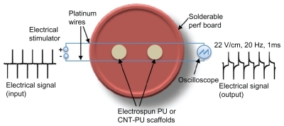
Biphasic electrical pulses (1 msec pulse width) delivered at 20 Hz were applied using a High-Power BiPhase Current Stimulator (model 701C, Aurora Scientific, Ontario, Canada) in trigger mode. Electrical stimulation was performed twice a day on the last two days of culture (four days total). The setup for the electrical stimulation studies consisted of a six-well plate with circularly solderable perf boards (heat-resistant pieces of glass-epoxy material with perforations arranged in a grid) and platinum wires (). The platinum wires were connected to the electrical stimulator, which was placed outside the incubator, and an oscilloscope was used to measure the output signals. The electrospun polyurethane carbon nanotube films were punched (8 mm in diameter) and placed between two platinum wires. The films were placed in the same plane as the wires in order to align them with the electrical field. The distance from the wires to the films was 1.5 cm. The average electrical field strength measured by oscilloscope was 22 V/cm. Micro cover glasses (VWR) were sputter-coated with gold in a thickness of 8 nm to increase its electrical conductivity. Glass and gold-coated glass were used as a control for the cell cultures with electrical stimulation. The cell culture with electrical stimulation was repeated three times.
Figure 1 A schematic diagram shows experimental setup for applying the biphasic pulsatile electrical field stimuli to myoblasts seeded on electrospun polyurethane only or polyurethane carbon nanotube scaffolds.
Abbreviations: CNT, carbon nanotubes; PU, polyurethane.
Statistical analysis
All quantitative data are reported as the mean ± standard error of the mean. Statistical comparisons using KaleidaGraph software (Synergy Software, Reading, PA) were based on an analysis of variance and Tukey’s test for pairwise comparisons. A value of P < 0.05 was considered statistically significant.
Results
Characterization of electrospun polyurethane carbon nanotube scaffolds
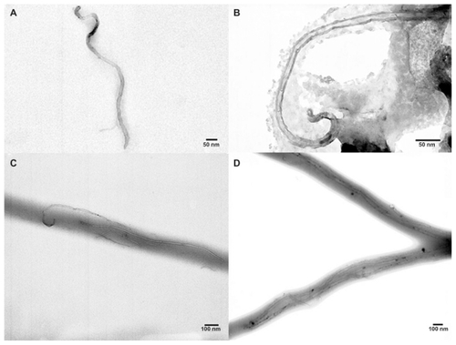
Random fibrous and high porous films were fabricated by electrospinning of polyurethane containing either SWNT or MWNT. shows scanning electron micrographs of the electrospun fibers. show images of the SWNT and MWNT before electrospinning, respectively. SWNT or MWNT were encapsulated inside the polyurethane fibers as confirmed by transmission electron microscopy ().
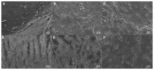
Figure 2 Scanning electron microscopy images of electrospun scaffolds. (A) 5PU, (B) SWNT-5PU, (C) MWNT-5PU, (D) 10PU, (E) SWNT-10PU, and (F) MWNT-10PU.
Note: Scale bars are 20 μm in (−1) and 4 μm in (−2).
Abbreviations: MWNT, multiwalled nanotubes; SWNT, single-walled nanotubes; 5PU, 5% w/v polyurethane; 10PU, 10% w/v polyurethane.
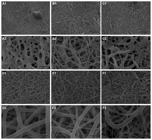
Figure 3 Transmission electron microscopic images. Electrospun (A) SWNT, (B) MWNT, (C) SWNT-10PU, and (D) MWNT-10PU.
Abbreviations: MWNT, multiwalled nanotubes; SWNT, single-walled nanotubes; 10PU, 10% w/v polyurethane.
Ultrafine interconnected and randomly aligned fibers with angular pores were observed on the CNT-10PU and 10PU films. By contrast, CNT-5PU and 5PU films had a melted-fiber matrix appearance, with mixed-shape (oval, circular, and angular) pores. Average pore areas and fiber diameters of the CNT-5PU and 5PU films were less than those in the CNT-10PU and 10PU films (). The average fiber diameters of the 10PU, SWNT-10PU, and MWNT-10PU films (in the region of 1 μm) were greater than that of the 5PU, SWNT-5PU, and MWNT-5PU films (in the region of 500 nm).
Table 1 Physical properties of electrospun SWNT-PU, MWNT-PU, and polyurethane only films (polyurethane 5% and 10% w/v)
Average contact angle values for the polyurethane carbon nanotube and polyurethane alone films are shown in . The results show that the average contact angles of both water and glycerol on the polyurethane carbon nanotube (both 5PU and 10PU) films were significantly lower than the average contact angles measured on polyurethane only (both 5PU and 10PU) films, suggested that the hydrophilicity of carbon nanotube-containing films was enhanced due to the incorporation of carbon nanotubes with the polyurethane. Specifically, the average contact angles (water, glycerol) of 5PU scaffolds were significantly greater than that of SWNT- 5PU and MWNT- 5PU. Similarly, the average contact angle (water, glycerol) of 10PU scaffolds was significantly higher when compared with SWNT-10PU and MWNT-10PU scaffolds.
Table 2 Contact angle measurement of electrospun SWNT-PU, MWNT-PU, and polyurethane only films with water and glycerol
Mechanical properties of electrospun polyurethane carbon nanotube scaffolds
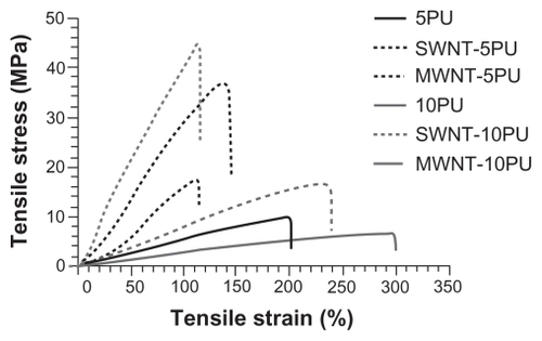
The ultimate tensile strengths of 5PU and 10PU films increased after incorporating SWNT and MWNT ( and ). The Young’s modulus (stiffness) of CNT- 5PU and CNT-10PU films was enhanced when compared with 5PU and 10PU (), respectively. In contrast, the elongation at breaks of CNT-5PU and CNT-10PU were decreased when compared with 5PU and 10PU, respectively. Hence, the incorporation of SWNT or MWNT in polyurethane fibers enhanced ultimate tensile strength and stiffness, but decreased the elongation distances of the scaffolds.
Figure 4 Tensile stress–strain curve of electrospun CNT-PU and polyurethane scaffolds.
Abbreviations: MWNT, multiwalled nanotubes; SWNT, single-walled nanotubes; 5PU, 5% w/v polyurethane; 10PU, 10% w/v polyurethane.
Electrical conductivity of electrospun polyurethane carbon nanotube scaffolds
summarizes the electrical conductivity (σ) of all scaffolds used in the present study. The electrical conductivity of the 5PU and 10PU films was zero, because these films are insulators and cannot readily conduct electricity. The electrical conductivity of the gold-coated glasses was about 0.07 S m−1, while the uncoated glass surfaces were not conductive.
Table 3 Electrical conductivity of electrospun SWNT-PU, MWNT-PU, and polyurethane only films
Cell morphology
The scanning electron micrographs in show the myotube sheets formed on the SWNT-5PU, MWNT-5PU, SWNT-10PU, MWNT-10PU, and control (5PU and 10PU) scaffolds after four days of culture. Fewer multinucleated myotubes were observed on the 5PU and SWNT-5PU scaffolds compared with the others. Importantly, the myotube sheets were denser on the CNT-10PU and 10PU films (interconnected fibers with angular pores) when compared with the CNT-5PU and 5PU films (melted-fiber matrices with oval, circular, and angular pores).
Figure 5 Scanning electron micrographs of C2C12 myoblasts cultured (four days) on electrospun scaffolds. (A) 5PU, (B) SWNT-5PU, (C) MWNT-5PU, (D) 10PU, (E) SWNT-10PU, and (F) MWNT-10PU. Scale bars are 20 μm.
Abbreviations: MWNT, multiwalled nanotubes; SWNT, single-walled nanotubes; 5PU, 5% w/v polyurethane; 10PU, 10% w/v polyurethane.
Cell proliferation
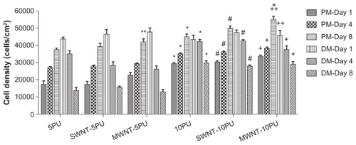
To study the viability of myoblasts on the composite SWNT or MWNT scaffolds, cells were cultured for eight days in proliferation media followed by an additional eight days in differentiation media. Viability was then measured using a cell proliferation (MTS) assay (). Electrospun SWNT-5PU, MWNT-5PU, SWNT-10PU, and MWNT- 10PU scaffolds were more cytocompatible with myoblasts and conducive to cell proliferation when compared with the control groups (5PU and 10PU scaffolds). Specifically, myoblast numbers on the MWNT-PU (both 5PU and 10PU) scaffolds were significantly greater than those on the 5PU and 10PU scaffolds after eight days of culture in proliferation media. However, numbers of cells on the SWNT-PU (both 5PU and 10PU) scaffolds were not significantly greater than those on the 5PU and 10PU scaffolds after eight days of culture in proliferation media. Importantly, CNT-10PU and 10PU films promoted significant myoblast proliferation after days 1, 4, and 8 of culture when compared with electrospun CNT- 5PU and 5PU films. C2C12 myoblast differentiation and fusion into myotubes has been correlated with decreased cell proliferation.Citation3 As expected, cell populations on most of the polyurethane carbon nanotubes and polyurethane only scaffolds decreased significantly after the culture media was shifted from proliferation to differentiation media.
Figure 6 MTS assay results in proliferation and differentiation media.
Notes: Values are presented as the mean ± standard error of the mean (n = 3). *P < 0.01 when compared with 5PU-alone at each same time point; #P < 0.01 when compared with SWNT-5PU at same time point; +P < 0.01 when compared with MWNT-5PU at same time point; ++P < 0.05 when compared with 10PU-alone at same time point; **P < 0.05 when compared with 5PU-alone at same time point.
Abbreviations: PM, proliferation media; DM, differentiation media; MWNT, multiwalled nanotubes; SWNT, single-walled nanotubes; 5PU, 5% w/v polyurethane; 10PU, 10% w/v polyurethane.
Myotube formation without electrical stimulation
Myoblasts expressed normal differentiation proteins (myosin heavy chain and Myf-5) and fused into multinucleated myotubes on the polyurethane carbon nanotube and polyurethane only scaffolds (). Loose fusion of differentiated myoblasts into myotubes was observed on the 5PU, SWNT-5PU, and MWNT-5PU scaffolds after four days in proliferation media. To analyze the effect of carbon nanotubes on the differentiation of myoblasts, the number, diameter, length, and area of multinucleated fused myotubes were measured and plotted (). The myotube number on the 10PU scaffolds was significantly greater than that on the 5PU scaffolds. Similarly, the numbers of myotubes were greater on the SWNT-10PU and MWNT-10PU scaffolds when compared with the SWNT-5PU and MWNT-5PU scaffolds.
Figure 7 Immunochemistry staining after four days of culture on electrospun scaffolds. (A) 5PU, (B) SWNT-5PU, (C) MWNT-5PU, (D) 10PU, (E) SWNT-10PU, and (F) MWNT-10PU. (−1) represents myosin heavy chains in green and (−2) represents Myf-5 in red. Cell nuclei were stained with DAPI in blue.
Note: Scale bars are 40 μm.
Abbreviations: MWNT, multiwalled nanotubes; SWNT, single-walled nanotubes; 5PU, 5% w/v polyurethane; 10PU, 10% w/v polyurethane.
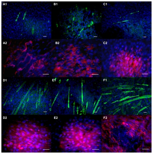
Figure 8 Quantification of myotube organization and morphology on electrospun scaffolds. (A) myotube number (count/cm2) and area (μm2/myotube), (B) myotube length and width (μm/myotube) after four days of culture.
Notes: Values are presented as the mean ± standard error of the mean. *,+,#P < 0.05 versus all 5PU scaffolds; **P < 0.05 versus 10PU; ***P < 0.05 versus 10PU and SWNT-10PU; ++P < 0.05 versus all 5PU and 10PU scaffolds; &P < 0.05 versus MWNT-5PU; and &&P < 0.05 versus all samples.
Abbreviations: MWNT, multiwalled nanotubes; SWNT, single-walled nanotubes; 5PU, 5% w/v polyurethane; 10PU, 10% w/v polyurethane.
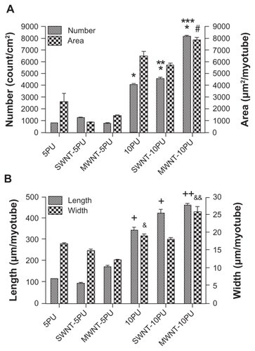
The numbers of myotubes on the MWNT-10PU scaffolds were significantly greater than those on the 10PU and SWNT- 10PU scaffolds. The aspect ratios of the width to length of myotubes on the 5PU, SWNT-5PU, MWNT- 5PU, 10PU, SWNT-10PU, and MWNT-10PU scaffolds were 0.15, 0.16, 0.07, 0.06, 0.04, and 0.06, respectively. Importantly, myotube number and length increased significantly in the CNT-10PU and 10PU scaffolds compared with the CNT- 5PU and 5PU scaffolds. This pattern did not hold true for myotube area or width.
Myotube formation with electrical stimulation
Immunofluorescent images () confirmed the presence of multicellular myotubes after electrical stimulation. The number of myoblasts on the control materials (glass and gold-coated glass) increased slightly after electrical stimulation. Fusion of myoblasts was slightly greater on gold-coated glass when compared with bare glass. The number and length of myotubes on SWNT-5PU and MWNT-5PU scaffolds were significantly greater than those on 5PU (insulator) in the presence of electrical stimulation (). Similarly, the number and length of myotubes on MWNT-10PU scaffolds were significantly greater than those on 10PU scaffolds (insulator). The additional immunofluorescence images from confocal microscopy () show that myotube formation on the carbon nanotube-containing scaffolds was greater than that on polyurethane alone in the presence of electrical stimulation.
Figure 9 Immunofluorescence images of C2C12 cultured for four days on (A) glass, (B) 5PU, (C) SWNT-5PU, (D) MWNT-5PU, (E) gold sputter-coated glass, thickness about 8 nm, (F) 10PU, (G) SWNT-10PU, and (H) MWNT-10PU. (−1) indicates without electrical stimulation and (−2) indicates with electrical stimulation.
Note: Scale bars are 50 μm. Myosin heavy chains were stained with fluorescein (green) and nuclei were marked with propidium iodide (red).
Abbreviations: MWNT, multiwalled nanotubes; SWNT, single-walled nanotubes; 5PU, 5% w/v polyurethane; 10PU, 10% w/v polyurethane.
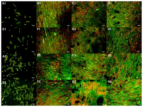
Figure 10 Quantification of myotube organization and morphology on electrospun CNT-PU and polyurethane scaffolds with and without electrical stimulation. (A) Myotube number (count/cm2) and (B) myotube length (μm/myotube) after four days of culture.
Notes: Values are presented as the mean ± standard error of the mean. (A) *P < 0.05 versus all samples; **P < 0.05 versus all samples; +P < 0.05 versus SWNT-/MWNT-5PU, SWNT-10PU, 5PU, and 5PU with electrical stimulation. (B) *P < 0.05 versus all not electrically stimulated samples, 5PU (electrically stimulated), and 10PU (electrically stimulated); **P < 0.05 versus MWNT/SWNT- 5PU, 5PU, 10PU, and 5PU (electrically stimulated); +P < 0.05 MWNT-5PU, 5PU, and 10PU; ++P < 0.05 versus 5PU.
Abbreviations: MWNT, multiwalled nanotubes; SWNT, single-walled nanotubes; 5PU, 5% w/v polyurethane; 10PU, 10% w/v polyurethane.
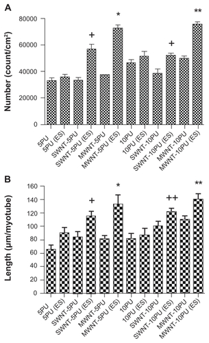
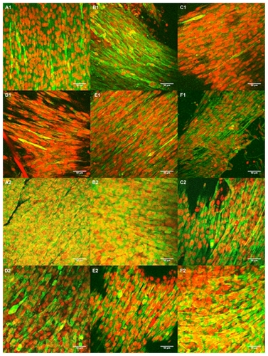
Figure 11 Confocal images of C2C12 seeded for four days on (A) 5PU, (B) SWNT-5PU, (C) MWNT-5PU, (D) 10PU, (E) SWNT-10PU, and (F) MWNT-10PU. (−1) indicates without electrical stimulation and (−2) indicates with electrical stimulation. Myosin heavy chains were stained with fluorescein (green) and cell nuclei were marked with propidium iodide (red).
Abbreviations: MWNT, multiwalled nanotubes; SWNT, single-walled nanotubes; 5PU, 5% w/v polyurethane; 10PU, 10% w/v polyurethane.
Discussion
Scaffolds for skeletal muscle tissue engineering should provide stable support for tissue growth that resists stress from contractile forces and prevents tissue degeneration and deformation. The present study explored myotube formation on electrically conductive scaffolds. To accomplish this, carbon nanotubes were blended into a medical grade, nondegradable polyurethane and electrospun to form a tissue scaffold. A medical grade polymer was used so that if any toxic effects were observed, they would most likely be attributable to the presence of carbon nanotubes, but no obvious toxicity was observed. Once prepared, the composite material was characterized and the effects of electrical stimulation on myotube formation were evaluated.
Characterization
The mechanical/electrical properties and hydrophilicity of the carbon nanotube polymer composite materials primarily depend on loading, aspect ratio, orientation, and dispersion of carbon nanotubes in the composite matrix.Citation26–Citation28 Because SWNT and MWNT have an extremely high modulus (about 1 TPa) along their length,Citation29,Citation30 their use can enhance the mechanical properties of composite scaffolds. Sen et al reported that the tensile strength of electrospun polyurethane SWNT films (about 50–100 mm in thickness) increased from 7.02 (for electrospun polyurethane) to 10.26 MPa when the weight ratio of SWNT to polyurethane was 1:100.Citation31 They also reported that the Young’s modulus of electrospun polyurethane SWNT films was enhanced while the elongation at break was decreased. In our study, a higher weight ratio of SWNT to 5PU (1:25) and of SWNT to 10PU (1:50) was used. Our results agree with those of others that incorporation of carbon nanotubes in polyurethane can improve the tensile strength and the Young’s modulus, but decrease the elongation distances of these materials.
In addition to changes in mechanical strength, incorporation of carbon nanotubes can change the hydrophilicity of scaffolds. Our study shows that polyurethane carbon nanotube films (both 5PU and 10PU) appear to be more hydrophilic than polyurethane films (both 5PU and 10PU), as confirmed by contact angle measurements (). Although the contact angle measurements can only compare relative hydrophilicity among several composite scaffolds, one possible reason for this change to more hydrophilicity upon addition of carbon nanotubes is that surface roughness increased. This may have had a beneficial effect because it may increase protein absorption, and thus promote cell proliferation and differentiation. For example, Khang et al found that high ratios of MWNT coated with polyurethane provided a more hydrophilic surface because of greater nanosurface roughness, even though carbon nanotubes themselves possess extremely hydrophobic surfaces.Citation32 They suggested that MWNT coated with polyurethane promoted adsorption of fibronectin, a protein well known to be critical in mediating the adhesion of anchor-dependent cells. Further studies using atomic force microscopy would confirm if the nanosurface of this particular system becomes rougher.
Incorporation of nanotubes not only changes the mechanical properties of cells, but also may change the biological response of cells to the material. Topography, fiber diameter, and orientation of scaffolds have also been reported to influence myoblast responses (morphology, proliferation, and differentiation).Citation3,Citation6,Citation33,Citation34 In the present study, myotube formation without electrical stimulation was dependent on the morphology of the electrospun composite scaffolds. Specifically, the myotube number and length on the CNT-5PU and 5PU scaffolds were significantly less than those on the CNT-10PU and 10PU scaffolds. The myotubes formed on the randomly oriented fibers of the electrospun scaffolds in the present study were mainly aligned in the same direction, as shown in . It has been shown that C2C12 myoblasts seeded onto a gelatin-coated or fibronectin-coated nonwoven electrospun polylactic acid fiber mesh (diameter approximately 500 nm) developed a disordered F actin filament arrangement on randomly oriented fiber meshes.Citation3 In contrast, in aligned fiber meshes, the filaments formed in an orderly fashion and aligned with the fibers on the mesh. Liao et al reported that myoblasts on electrospun polyurethane films containing aligned fibers showed significant cytoplasmic elongation compared with those cultured on films containing randomly aligned fibers (average elongation factor 13.5 for aligned versus 3.7 for random topography).Citation2 However, they found that fiber diameters between 600 nm to 10 μm produced no statistically significant differences in alignment and cell elongation factors. The average fiber diameters of electrospun scaffolds in the present study were varied in a more narrow range, ie, 500 nm to 1.5 μm (). Another study found that myoblasts formed longer myotubes in the unidirectional fiber orientation of electrospun polycaprolactone/collagen nanofiber meshes compared with the myotubes that formed on nanofiber meshes containing randomly oriented fibers.Citation6 In addition, myoblasts cultured on micropatterned polydimethylsiloxane containing parallel microgrooves developed a well organized F actin assembly along the direction of the microgrooves.Citation34 Although in the present study the randomly aligned fibers were fabricated, further studies could be done on the aligned fiber scaffolds to study myotube formation.
When myotubes contract, they generate force that is distributed throughout the scaffold. Therefore, adhesion between the cell scaffolds has to be strong enough to support the cell differentiation process.Citation35 On the other hand, the contractile force generated from contraction of myotubes on rigid scaffolds could cause late detachment of cells.Citation36 For example, the low stiffness (Young’s modulus 4 ± 1 kPa) of a polylactic-co-glycolic acid (PLGA) scaffold contains fewer multinucleated C2C12 cells when compared with a 75/25 PLGA (Young’s modulus 280 ± 33 kPa) scaffold.Citation7 Cells on PLGA scaffolds had a small round shape instead of the typical elongated shape of myotubes after 14 days of culture, as observed for the 75/25 PLGA scaffolds. However, we found that the stiffness of the polyurethane carbon nanotube scaffolds in the region of 103 kPa () can also promote myoblast organization and differentiation into myotubes. The multinucleated myotubes were mainly aligned in the same direction and fused together to form long myofiber-like cells on all polyurethane carbon nanotube and polyurethane only scaffolds in the present study. Scaffold stiffness could modulate the level of skeletal myotube differentiation through cell-substrate interactions.Citation37 In the present study, the striation of myotubes was not observed on polyurethane carbon nanotube or polyurethane only scaffolds after three days of differentiation. It is possible that a longer period after differentiation is better, because the striations of myotubes (alignment of myosin and actin into repeated units in mature skeletal muscle) usually emerge in the later stages of differentiation. It is also possible that polyurethane carbon nanotube and polyurethane only scaffolds are too stiff to induce striation of myotubes. Engler et al suggested that myoblasts could differentiate more readily on elastic or softer surfaces.Citation37 Specifically, myotubes were found to be formed with a higher degree of striation when cultured on softer fibers (0.5 MPa) rather than on stiffer fibers (22 MPa) in aligned electrospun polyurethane scaffolds.Citation2 In that study, at day 14 after differentiation, about 55% of myotubes cultured on the randomly orientated polyurethane fibers and 70% cultured on aligned polyurethane fibers showed striations. Further studies are needed to clarify the appropriate time of cultures and optimum stiffness of electrospun polyurethane carbon nanotube scaffolds to induce possibly mature myotube formation.
Electrical stimulation
The electrical properties of electrospun SWNT-PU and MWNT-PU also affected cell differentiation in the present study. The electrical conductivity of SWNT-PU and MWNT-PU scaffolds () was significantly increased after incorporation of SWNT or MWNT into the electrospun polyurethane fibers. The conductivity of MWNT-PU scaffolds was similar to the reported conductivity of scaffolds prepared by loading polyurethane with 5 wt% of MWNT powder (0.052 S m−1 and 0.1 S m−1).Citation38,Citation39 The myotube number was greater on the higher conducting scaffolds. For example, the number of myotubes on the MWNT-10PU (σ about 0.023 S m−1) was significantly greater than that on the SWNT- 10PU (σ about 0.009 S m−1) without electrical stimulation, as shown in . However, there was no statistically significant difference in myotube number among the SWNT-5PU, MWNT-5PU, and polyurethane (insulator) scaffolds in the absence of electrical stimulation. In addition, myoblasts fused together and developed more fiber-like morphology on electrically conductive (gold-coated) glass than that on nonconductive glass, on which clusters of round myoblasts were observed. The number of myotubes on the polyurethane carbon nanotube scaffolds was significantly greater than that on gold-coated glass. This is because the glass surface is fully rigid, although the electrical conductivity of gold-coated glasses is similar to that of polyurethane carbon nanotube scaffolds. Importantly, these findings suggest that electrically conductive scaffolds promote more multinucleated myotube formation compared to nonconductive scaffolds on applying electrical stimulation.
Various features of electrical stimulation can influence cell differentiation, including duration of current flow (pulse width), impulse amplitude, frequency, pulse signal characteristics (positive, negative, or biphasic signals), and percentage of current flow into cell membranes. A previous study reported that a positive direct current at 20 V, 1 Hz, and 1 msec pulse width was applied three times a day for at least 14 days (one hour of application with five hours of rest time).Citation2 This electrical stimulation protocol promoted striation in myoblasts (10% at day 0, 45% at day 4, and 70%–85% at day 7, compared with the nonstimulated control). Tandon et al applied positive square pulses (5 V, 1 Hz, 5 V, 1 msec duration), which enhanced the contractile behavior of cardiomyocytes (about seven-fold higher than in nonstimulated constructs after eight days).Citation40 Chui et al showed that when symmetrically square biphasic (positive and negative) electrical signals (2.5 V, 1 Hz, 1 msec duration) were applied to cardiomyocyte-seeded polyethylene glycol constructs in vitro, cell elongation was increased.Citation41 Moreover, in the same study, a higher cell density was observed, along with the presence of cross-striation, and expression of Connexin 43 (a gap junction protein that propagates electrical signaling in cardiac muscle) was increased. Our results suggest that a nonsymmetrical biphasic electrical signal can also be used to augment multinucleated myotube formation from skeletal myoblasts rather than the more common use of symmetrical biphasic (positive and negative) or uniphase pulse signals.
Conclusion
Proliferation and differentiation of C2C12 skeletal muscle cells on electrospun SWNT or MWNT and polyurethane scaffolds was studied with and without electrical stimulation. The incorporation of SWNT or MWNT changed the physical, mechanical, and electrical properties of the scaffolds. Without electrical stimulation, the morphology of the electrospun polyurethane carbon nanotubes and polyurethane only scaffolds had a prominent effect on skeletal myoblast proliferation and differentiation. Our results suggest that multinucleated myotubes are more readily formed on carbon nanotube-containing scaffolds than on nonconductive scaffolds after electrical stimulation. Future studies using electrospun polyurethane carbon nanotube scaffolds are needed to determine if they can be adequately vascularized and innervated to aid in successful skeletal muscle regeneration. Importantly, electrically conductive materials have the potential to aid in the engineering of functional skeletal muscle tissues.
Acknowledgments
The authors thank Professor Martin Childers for the use of his high-power biphase current stimulator, Jennifer L. Olson, for her editorial assistance with this manuscript, and are grateful for the funding support received from the National Institutes of Health (1RO1ES016246).
Disclosure
The authors report no conflicts of interest in this work.
References
- KondohHSawaYMiyagawaSLonger preservation of cardiac performance by sheet-shaped myoblast implantation in dilated cardiomyopathic hamstersCardiovasc Res200669246647516423569
- LiaoICLiuJBBursacNLeongKWEffect of electromechanical stimulation on the maturation of myotubes on aligned electrospun fibersCell Mol Bioeng200812–313314519774099
- HuangNFPatelSThakarRGMyotube assembly on nanofibrous and micropatterned polymersNano Lett20066353754216522058
- KumbarSGJamesRNukavarapuSPLaurencinCTElectrospun nanofiber scaffolds: engineering soft tissuesBiomed Mater20083303400218689924
- LanMAGersbachCAMichaelKEKeselowskyBGGarcíaAJMyoblast proliferation and differentiation on fibronectin-coated self assembled monolayers presenting different surface chemistriesBiomaterials200526224523453115722121
- ChoiJSLeeSJChristGJAtalaAYooJJThe influence of electrospun aligned poly(ɛ-caprolactone)/collagen nanofiber meshes on the formation of self-aligned skeletal muscle myotubesBiomaterials200829192899290618400295
- Levy-MishaliMZoldanJLevenbergSEffect of scaffold stiffness on myoblast differentiationTissue Eng Part A200915493594418821844
- DadoDLevenbergSCell-scaffold mechanical interplay within engineered tissueSemin Cell Dev Biol200920665666419596326
- MaPXBiomimetic materials for tissue engineeringAdv Drug Delivery Rev2008602184198
- ShinHJoSMikosAGBiomimetic materials for tissue engineeringBiomaterials200324244353436412922148
- Brett RungeMDadsetanMBaltrusaitisJThe development of electrically conductive polycaprolactone fumarate-polypyrrole composite materials for nerve regenerationBiomaterials201031235916592620483452
- EvansAJThompsonBCWallaceGGPromoting neurite outgrowth from spiral ganglion neuron explants using polypyrrole/BDNF-coated electrodesJ Biomed Mater Res A10200991124125018814235
- JunIJeongSShinHThe stimulation of myoblast differentiation by electrically conductive sub-micron fibersBiomaterials200930112038204719147222
- Collazos-CastroJEPoloJLHernandez-LabradoGRPadial-CaÒeteVGarcÌa-RamaCBioelectrochemical control of neural cell development on conducting polymersBiomaterials201031359244925520864170
- SupronowiczPRAjayanPMUllmannKRArulanandamBPMetzgerDWBiziosRNovel current-conducting composite substrates for exposing osteoblasts to alternating current stimulationJ Biomed Mater Res200259349950611774308
- AbarrategiAGutiérrezMCMoreno-VicenteCMultiwall carbon nanotube scaffolds for tissue engineering purposesBiomaterials20082919410217928048
- ShiXHudsonJLSpicerPPTourJMKrishnamoortiRMikosAGInjectable nanocomposites of single-walled carbon nanotubes and biodegradable polymers for bone tissue engineeringBiomacromolecules2006772237224216827593
- MacDonaldRALaurenziBFViswanathanGAjayanPMStegemannJPCollagen–carbon nanotube composite materials as scaffolds in tissue engineeringJ Biomed Mater Res A200574A348949615973695
- HanZKongHMengJWangCXieSXuHElectrospun aligned nanofibrous scaffold of carbon nanotubes-polyurethane composite for endothelial cellsJ Nanosci Nanotechnol2009921400140219441533
- MattsonMHaddonRRaoAMolecular functionalization of carbon nanotubes and use as substrates for neuronal growthJ Mol Neurosci200014317518210984193
- HuHNiYMontanaVHaddonRCParpuraVChemically functionalized carbon nanotubes as substrates for neuronal growthNano Lett20044350751121394241
- HuHNiYMandalSKPolyethyleneimine functionalized single-walled carbon nanotubes as a substrate for neuronal growthJ Phys Chem B2005109104285428916851493
- SmitsFMMeasurement of Sheet Resistivities with the four-point probeBell Syst Tech J195837711718
- YaffeDSaxelOSerial passaging and differentiation of myogenic cells isolated from dystrophic mouse muscleNature19772705639725727563524
- BaderDMasakiTFischmanDAImmunochemical analysis of myosin heavy-chain during avian myogenesis in vivo and in vitroJ Cell Biol19829537637706185504
- WongKKZinke-AllmangMHutterJLHrapovicSLuongJHTWanWThe effect of carbon nanotube aspect ratio and loading on the elastic modulus of electrospun poly(vinyl alcohol)-carbon nanotube hybrid fibersCarbon2009471125712578
- KashiwagiTFaganJDouglasJFRelationship between dispersion metric and properties of PMMA/SWNT nanocompositesPolymer2007481648554866
- MacDonaldRAVogeCMKariolisMStegemannJPCarbon nanotubes increase the electrical conductivity of fibroblast-seeded collagen hydrogelsActa Biomater2008461583159218706876
- AjayanPMNanotubes from carbonChem Rev19999971787180011849010
- YuMFFilesBSArepalliSRuoffRSTensile loading of ropes of single wall carbon nanotubes and their mechanical propertiesPhys Rev Lett20008424555210990992
- SenRZhaoBPereaDPreparation of single-walled carbon nanotube reinforced polystyrene and polyurethane nanofibers and membranes by electrospinningNano Lett200443459464
- KhangDKimSYLiu-SnyderPPalmoreGTDurbinSMWebsterTJEnhanced fibronectin adsorption on carbon nanotube/poly(carbonate) urethane: independent role of surface nano-roughness and associated surface energyBiomaterials200728324756476817706277
- WangPYYuHTTsaiWBModulation of alignment and differentiation of skeletal myoblasts by submicron ridges/grooves surface structureBiotechnol Bioeng2010106228529420148416
- HuangNFLeeRJLiSEngineering of aligned skeletal muscle by micropatterningAm J Transl Res201021435520182581
- NeumannTHauschkaSDSandersJETissue engineering of skeletal muscle using polymer fiber arraysTissue Eng200395995100314633383
- ClemmensEWRegnierMSkeletal regulatory proteins enhance thin filament sliding speed and force by skeletal HMMJ Muscle Res Cell Motil200425751552515711882
- EnglerAJGriffinMASenSBönnemannCGSweeneyHLDischerDEMyotubes differentiate optimally on substrates with tissue-like stiffnessJ Cell Biol2004166687788715364962
- SahooNGJungYCYooHJChoJWInfluence of carbon nanotubes and polypyrrole on the thermal, mechanical and electroactive shape-memory properties of polyurethane nanocompositesComposites Science and Technology200767919201929
- ChoJWKimJWJungYCGooNSElectroactive shape-memory polyurethane composites incorporating carbon nanotubesMacromol Rapid Commun2005265412416
- TandonNCannizzaroCChaoPHElectrical stimulation systems for cardiac tissue engineeringNat Protoc20094215517319180087
- ChiuLLIyerRKKingJPRadisicMBiphasic electrical field stimulation aids in tissue engineering of multicell-type cardiac organoidsTissue Eng Part A20111711–121465147718783322