Abstract
An implantable model system was developed to investigate the effects of nanoscale surface properties on the osseointegration of titanium implants in rat tibia. Topographical nanostructures with a well-defined shape (semispherical protrusions) and variable size (60 nm, 120 nm and 220 nm) were produced by colloidal lithography on the machined implants. Furthermore, the implants were sputter-coated with titanium to ensure a uniform surface chemical composition. The histological evaluation of bone around the implants at 7 days and 28 days after implantation was performed on the ground sections using optical and scanning electron microscopy. Differences between groups were found mainly in the new bone formation process in the endosteal and marrow bone compartments after 28 days of implantation. Implant surfaces with 60 nm features demonstrated significantly higher bone-implant contact (BIC, 76%) compared with the 120 nm (45%) and control (57%) surfaces. This effect was correlated to the higher density and curvature of the 60 nm protrusions. Within the developed model system, nanoscale protrusions could be applied and systematically varied in size in the presence of microscale background roughness on complex screw-shaped implants. Moreover, the model can be adapted for the systematic variation of surface nanofeature density and chemistry, which opens up new possibilities for in vivo studies of various nanoscale surface-bone interactions.
Introduction
Osseointegration is an important requirement for the clinical success of dental implants.Citation1 The osseointegration process itself is fairly complex and there are many factors that influence the formation and maintenance of bone at the implant surface. Physicochemical characteristics of the implant surface, such as topography, chemistry, wettability and electrical charge, affect the biological reactions occurring at the interface of tissue and implant.Citation2,Citation3 For example, a micron-scale rough surface prepared by grit blasting and subsequent acid etching induces a rapid increase in bone accrual at titanium implants.Citation4 However, these and other modifications of implant surface roughness at the micrometer level may also result in unintentional changes at the nanometer level and might contribute to changes in surface chemistry.Citation5 It is therefore difficult to determine which of these changes predominantly contribute to the biological effect, unless the performed modifications are characterized and systematically varied down to nanoscale level, which requires a specially designed experimental model system. So far, a number of nanopatterning or nanoreplication methods have been developed for the successful preparation of two-dimensional model surfaces compatible with in vitro systematic studies of surface nanoscale effects on cells.Citation4 Unfortunately, in vitro models do not generally represent the true complexity of the clinical situation. For this reason, the use of animal models is often an essential step in the biological evaluation of implant modifications prior to clinical use in humans.Citation6
Dental implants most often have complex three-dimensional geometry and high microscale surface roughness and, for this reason, the nanopatterning techniques used in the fabrication of in vitro models cannot be directly applied to the medical implants. Nevertheless, several surface treatment methods have been investigated for their potential usefulness in implant surface modification at nanoscale level.Citation4 For example, a nanoscale calcium-phosphate coating can be applied by electrochemical depositionCitation7 or hydroxyapatite nanoprecipitation.Citation8 The nanotubular structural modification of titanium has been achieved by anodization.Citation9 A titanium nanonodular structure can be produced by physical vapor depositions of titanium onto micro-textured titanium surfaces.Citation10 Other techniques, including the plasma-spraying, sol-gel and hydrothermal treatments, are available for titanium nanostructuring.Citation11 Although it has been demonstrated by the listed studies that nanostructures at the titanium implant surface induce a favorable bone response,Citation12 there is still a lack of reliable data on the specific effects of nanotopography on bone response, because many other variables (chemistry, porosity, crystallinity) simultaneously influence biomolecular and cellular interactions with these surfaces and it is therefore difficult to distinguish the surface feature that is responsible for the particular biological effect. For this reason, the aim of the present study is to develop an experimental model system, which enables the evaluation of the in vivo biological effects of systematic modifications of exclusively selected surface nanoscale properties. A specific case, in which the well-defined nanotopography of the implant is systematically altered without affecting other surface properties, such as chemical composition and topography at microscale, is chosen to demonstrate the applicability and usefulness of a model system of this kind.
Materials and methods
Preparation of the model implants
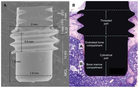
Eighty implants were manufactured by machining a commercially pure (grade II) titanium rod. The intraosseous part of the implant () was specially designed as a cylinder (1.8 mm in diameter, 1.5 mm in length) with threads at the top part (2.0 mm in diameter, 0.5 mm in length). The implants were divided into four groups. The cylindrical part for three of the groups was patterned with 60 nm, 120 nm and 220 nm semispherical protrusions respectively, while non-patterned machined titanium implants served as the control group.
Figure 1 (A) Overall SEM image showing the macroscopic design of the implant. (B) The cylindrical part of the implant protrudes into the marrow cavity without contacting the endosteal site of the opposite cortical bone. The histomorphometric measurement zones are schematically represented as (A and B) compartments, dividing the cylindrical part into two equal segments. Compartment (A) is expected to be dominated by the downgrowth of endosteal bone (distance osteogenesis). In contrast, compartment (B) is dominated by de novo formed bone (contact osteogenesis).
Abbreviation: SEM, scanning electron microscopy.
The topographic nanopatterning of the implants was performed by colloidal lithography.Citation13 First, the implants were cleaned ultrasonically in acetone, isopropyl alcohol and Milli-Q (Millipore Corp, USA) water for 5 minutes in each bath and dried under a nitrogen stream. The remaining organic residues were removed by oxygen plasma treatment (250 W, 250 mTorr, 2 minutes, Plasma Therm Batchtop RIE/PE m/95). A net positive charge on the implant surfaces was induced by soaking the implants in 2% wt/wt polydiallydimethyl ammonium chloride (Mw 200000–350000, Sigma-Aldrich® Corp, St Louis, MO, USA), 2% wt/wt polysodium 4-styrenesulfonate (Mw 70000, Sigma- Aldrich) and 5% wt/wt aluminum chloride hydroxide (chlorohydrol, Summit Reheis, Huguenot, NY, USA) solutions for 5 minutes each. The implants were washed with Milli-Q water and blow-dried by a nitrogen stream between each of these steps. The implants were then soaked in a 2% wt/wt colloidal solution (surfactant free white polystyrene latex, Invitrogen Corp, Carlsbad, CA, USA) so that negatively charged polystyrene nanoparticles were adsorbed on the positively charged implant surfaces, creating a monolayer of short-range ordered polymeric nanoparticles. Non-adsorbed particles were washed off the implants using Milli-Q water. The colloidal particles used in this study had nominal diameters of 50 nm, 110 nm and 190 nm, with an 8% deviation in size. In order to avoid the displacement and aggregation of the adsorbed nanoparticles due to capillary forces during the drying process, the particles were immobilized on the surface by heating them to the temperature above the glass transition (c. 100°C for polystyrene), creating a larger particle-to-implant contact area. The heat was applied by soaking the implants in fuming-hot ethylene glycol for a few seconds before washing with Milli-Q water and drying under a nitrogen stream. The adsorbed spherical polymeric particles on the implant surfaces were deformed to a semi-hemispherical shape by the additional heat treatment of the fabricated implants and adsorbed nanoparticles in an oven at 105°C–118°C for 1–2 minutes depending on the particle sizes. Finally, in order to achieve homogeneous chemistry on the implant surfaces, a 10–20 nm thick Ti layer was deposited by ion sputtering (FHR MS 150, [FHR Anlagenbau GmbH, Germany] 5 × 10⁻⁵ mbar, 0.33 kW) on all the implants (10 nm layer on 50 nm and 110 nm particles and 20 nm layer on 190 nm particles). The implants were stored in 70% ethanol until surgery.
Each particle size was used to nanopattern 20 implants (60 implants in total). An additional 20 implants without any nanoparticles were sputter-coated with Ti (10 nm thick layer) to be used as a reference.
Surface characterization
The chemical composition of the Ti coating was characterized by means of X-ray photoelectron spectroscopy (XPS [Electron Spectroscopy for Chemical Analysis]; PHI 5500C, Perkin-Elmer Corp, Eden Prairie, MN, USA). Surface topography at nanoscale was investigated by scanning electron microscopy (SEM; Supra 60 VP, Zeiss Carl Zeiss, Jena, Germany). The parameters of nanoparticle size, distribution density and coverage were obtained by SEM image analysis (average of three images) using ImageJ (National Institute of Health (NIH), USA) software.Citation14 The geometry and Ti coverage of a single 220 nm nano-semisphere was investigated by energy-filtered transmission electron microscopy (EFTEM) using a Titan™ 80–300 operating at 300 kV. Thin EFTEM-compatible foils revealing the cross-section of the nanostructure were prepared by using a flat silicon nitride membrane as a support and in situ protective platinum deposition, ion milling and section lift-out using a FEI Strata™ DB235 dual beam SEM/FIB (FEI Corp, OR, USA). Surface roughness at micron scale was analyzed using a Wyko NT1100 (Veeco, USA) non-contact optical profilometer. The wettability of the surfaces was measured by a Krüss DSA-10 MK2 (Krüss, Germany) contact angle goniometer. Water droplets (high-performance liquid chromatography [HPLC] grade water, Sigma-Aldrich) with a volume of about 500 pl were dispensed onto the surfaces of the implants using a Krüss DS3230 micro-dosing system. The images of the droplets were recorded for analysis within 1 second after dispensing.
Experimental design and implantation procedure
Twenty male Sprague-Dawley rats (250–350 g), fed on a standard pellet diet and water, were anesthetized using a Univentor 400 anesthesia unit (Univentor Ltd, Zejtun, Malta) under isoflurane (Isoba Vet, Schering-Plough Ltd, Uxbridge, UK) inhalation (4% with an air flow of 650 mL/min). Anesthesia was maintained by the continuous administration of isoflurane (2.7% with an air flow of 450 mL/min) via a mask. Each rat received analgesic (Temgesic 0.03 mg/kg, Reckitt and Coleman Ltd, Hull, Great Britain) subcutaneously postoperatively and the following 2 days, twice daily. After shaving and cleaning (5 mg/mL chlorhexidine in 70% ethanol), the medial aspect of the proximal tibial metaphysis was exposed through an anteromedial skin incision, followed by skin and periosteum reflection with a blunt instrument. Two holes were prepared in each metaphysis (proximally and distally) using subsequent enlarging (Ø1.4 mm and Ø1.8 mm burs) under profuse saline irrigation. A total of 80 implants were installed using a predesigned placement schedule to ensure maximum rotation for the different implant surfaces and placements. The subcutaneous layer of the wound was closed with resorbable polyglactin sutures (5–0, Vicryl, Ethicon, Johnson and Johnson International, Brussels, Belgium) and the skin was closed with transcutaneously placed non-resorbable nylon sutures (5–0, Ethilon, Ethicon, Johnson and Johnson, Brussels, Belgium). The animals were housed in groups and allowed free postoperative movement, with food and water ad libitum.
The retrieval procedure was performed at 7 days and 28 days (ten rats at each time point), where the animals were sacrificed using an overdose of barbiturate (Mebumal®, ACO Läkemedel AB, Solna, Sweden). The skin was reopened by blunt dissection and the bone with the implant was removed en bloc and immersed in formalin. The animal experiments were approved by the University of Gothenburg’s Local Ethics Committee for Laboratory Animals (Dnr 301/09).
Histology and histomorphometry
The formalin-fixed, tissue-implant bloc was dehydrated in a graded series of ethanol and embedded in LR white resin (London Resin Co, Ltd, Berkshire, UK) prior to cutting along the long axis of the implant using a diamond saw. Ground sections were prepared using sawing and grinding (EXAKT Apparatebau GmbH and Co, Norderstedt, Germany) until a final thickness of 10–20 μm was reached, after which they were stained with toluidine blue.
The bone-to-implant contact (BIC) and the relative amount of bone area (BA) around the cylindrical part of the implant were determined using light microscopy (Nikon Eclipse E600, Nikon Instruments Inc, NY, USA) at 20 times magnification. The BA was measured in the rectangular area extending 200 μm from the implant surface into bone. The analysis was performed on two separate compartments – Part A (proximal half-part of the cylinder) and Part B (distal half-part of the cylinder) – in order to distinguish the areas dominated by endosteal and marrow bone respectively ().
The counterparts of the embedded tissue implant blocs were also prepared for SEM analysis by coating them with a 10 nm layer of Au (FHR MS 150 sputtering system) to avoid charging under an e-beam. A Zeiss Supra 60 VP SEM was used in the back-scatter mode (20 kV acceleration, 8.4 mm working distance) to achieve chemical contrast in the images.
Statistics
Statistical analyses were performed by one-way analysis of variance (ANOVA) considering implant surface types as the independent variables and BIC or BA as the dependent variables. Tukey’s least significant difference post-hoc test was used for comparisons between the multiple groups. Statistical significance was indicated by P-levels of less than 5%.
Sample size (n = 10) estimation was performed using statistical power analysis (π > 80%) for a balanced ANOVA model using online software from the University of Iowa.Citation15 The standard deviation of populations values (SD(BIC) = 13, SD(BA) = 10) and the expected contrast of the mean values (μ(BIC) = 20, μ(BA) = 15) were based on previous experiments involving a rat tibia model and screw-shaped implants.Citation16
Results
Surface characterization
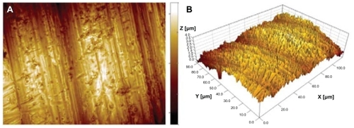
Surface observation of the cylindrical part of the implants by SEM and optical profilometry revealed microscale topography characteristic of metal-lathe-machined surfaces (). The topography was dominated by cutting-tool-induced periodic hierarchical structures aligned perpendicularly to the implant turning axis. The largest surface features, identified as surface waviness, had amplitude of about 1 μm and periodicity of 40 μm. The smaller scale features consisted of a range of parallel grooves and ridges which were about 0.5 μm in height and had periodicity of 3 μm (). In addition to the directional grooves, the entire surface was covered by isotropic topographic features with a summit density of 0.24 μm−2 and a height of up to 3.5 μm, resulting in root-mean- square overall roughness of 0.46 μm. The topography had slightly negative skewness, Ssk = −0.47, indicating asymmetry towards valleys, and kurtosis, Sku = 3.30, larger than Gaussian height distribution, indicating a predominance of somewhat large, sharp peaks and valleys.
Table 1 Microscale surface roughness parameters of the machined implant determined by optical profilometry
Figure 2 Surface microscale roughness of the cylindrical part of a machined titanium implant recorded with an optical profilometer. (A) top view, (B) three-dimensional view. In both images, the x, y and z range is 120, 90 and 4 μm respectively.
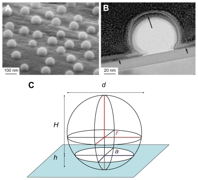
SEM imaging of nanostructured surfaces () revealed that surface patterning by colloidal lithography induced well-defined semispherical bump-shaped structures which were even in size (60 nm, 120 nm and 220 nm diameter) and uniformly distributed (36.6 μm−2, 15.9 μm−2 and 4.7 μm−2 density respectively). The particles successfully covered complex 3D geometries both at macroscale (cylindrical part of the implant) and at microscale (roughness induced by machining). EFTEM analysis of a 220 nm nano-semisphere on a flat support confirmed that the polystyrene semisphere was completely covered by a thin sputtered titanium layer (). The image also revealed that the adsorbed nanoparticle had the geometrical shape of a truncated sphere with a diameter d = 220 nm and height H = 160 nm ≈ 3/4 d. This enables the easy estimation of the surface area induced by nanopatterning ().
Figure 3 SEM micrographs of the cylindrical part of all implant groups. (A) 60 nm, (B) 120 nm, (C) 220 nm diameter semispheres and (D) a non-patterned machined titanium implant.
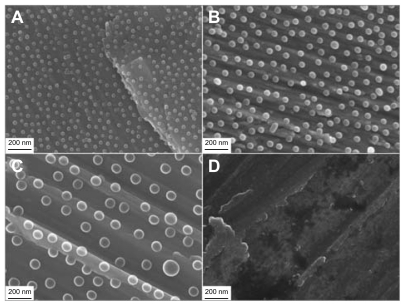
Figure 4 Geometrical shape and composition of nano-semispheres revealed by electron microscopy (A) SEM image of 220 nm semispherical nanostructures on the microscale topography of a machined implant, (B) TEM image of 220 nm nano-semispheres on a flat model surface shows complete coverage of a thin Ti sputtered layer (the black arrows), (C) the geometry of the nanoparticle modeled by a truncated sphere with a diameter of d = 220 nm and a height of H = 160 nm ≈ 3/4 d.
Abbreviations: SEM, scanning electron microscopy; TEM, transmission electron microscopy.
Abbreviation: SEM, scanning electron microscopy.
The induced area was calculated according to the geometry of a truncated sphere (representing an adsorbed nanoparticle) of radius r, which intersected the surface by a distance h, as shown in . The induced area is equal to Sdr = n(SS − SC − SI) = πn(d − h)2 = πnH2, where n is the particle distribution density (number of particles per surface area unit), SS is the surface area of a complete sphere (SS = 4πr2), SC is the surface area of a spherical cap reduced by the intersection (SC = 2πrh) and SD is the surface area of the circular intersection (SI = πa2). Furthermore, as indicated in , d = 2r is a diameter of the sphere, a2 = 2rh − h2 is a radius of the intersection and H = d − h is a height of the truncated sphere. The measured and calculated parameters of the nanopatterned surfaces are tabulated in .
Table 2 Nanoscale topography parameters determined by SEM
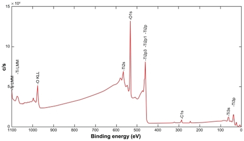
Surface chemical analysis () performed on nanopatterned flat discs by XPS revealed the following elemental composition of the sputtered Ti coatings: 37% titanium, 57% oxygen and 6% carbon. The observed titanium and oxygen ratio (0.65) was significantly higher than that of a stochiometric titanium dioxide (0.5), which indicated that the native titanium oxide was very thin and that sputter-cleaning preferentially removed oxygen from the surface. The carbon signal most likely originated from contamination by hydrocarbons adsorbed from ambient air, which were not completely removed by Ar ion beam sputter cleaning.
Figure 5 XPS spectra of the Ti coating after sputter-cleaning by Ar ions.
Abbreviation: XPS, X-ray photoelectron spectroscopy.
Water contact angles measured on the nanopatterned and reference implants revealed that titanium surfaces were hydrophilic (contact angle of 45.3 ± 2.2 degrees on the reference surface) and that surface hydrophilicity was further dramatically enhanced by the nanostructures (20.7° ± 1.0°, 16.7° ± 3.1° and 27.0° ± 2.2° on the surfaces patterned by the 60 nm, 120 nm and 220 nm features respectively), although all the surfaces had an identical chemical composition (Ti coating). The reduction in contact angles on the nanostructured surfaces might be expected, due to an increase in the surface area by nanostructures (up to 41%, ), as predicted by the Wenzel modelCitation17 and the cos θ* = S cos θ relationship, where S is the developed surface area and θ* and θ are the contact angles on rough and ideally flat surfaces respectively. However, the Wenzel model does not hold in our case when comparing the measured contact angles on surfaces with differently sized nanoparticles. Most likely, a hemi-wicking phenomenon occurs for the 220 nm nanobumps, where a thin water film impregnates the solid surface between the nanoparticles around the liquid drop due to capillary forces and reduces Wenzel wetting, as described by Quéré and Ishino.Citation18,Citation19
For such an effect to occur, the contact angle on flat surfaces should be below the critical angle defined as cos θc = (1 − φ)/(S − φ), where φ is the non-impregnated surface fraction (tops of the nanoparticles). Using the developed surface area and particle surface coverage tabulated in as S and φ values respectively, the critical angles are calculated as 34°, 48° and 51° corresponding to 60 nm, 120 nm and 220 nm particles. Clearly, the measured contact angle on the implant without nanoparticles (45°) is far below the critical angle calculated for 220 nm particles, which supports the hypothesis of a hemi-wicking type of wetting in this case.
Biological responses
The clinical healing of the installed implants was generally uneventful in all experimental animals, apart from one animal excluded from the study, which died during the operation. No operative or postoperative complications were encountered.
The implantation sites in both the distal and proximal tibia consist of cortical bone, which means that the threaded part of the implant is located within the cortical bone. The remaining cylindrical part of the implant protrudes into the marrow cavity without making contact with the endosteal surface of the opposite cortical bone (). In general, distinct bone formation on the endosteal side of the cortex in all implant groups was observed at the early time point. After 7 days of implantation, some of the bone fragments resulting from the drilling procedure at the implant site were seen. Few inflammatory cells and multinucleated cells were detected.
A similar pattern of bone apposition was observed for the surfaces of the 60 nm and 220 nm groups in comparison to the surfaces of the 120 nm and control groups (). This newly formed, mineralized tissue extended from the endosteum onto the implant surface of all implant groups, but it also grew directly (contact osteogenesis) on the surfaces of the implants of the 60 nm and 220 nm groups in both endosteal () and bone marrow compartments (). The newly formed woven bone, which could be distinguished from the pre-existing bone by its differential staining pattern, was deposited on the pre-existing bone or as interconnected islands/trabeculae in the bone marrow around the endosteal and marrow regions of the implant (). The trabeculae formed a randomly oriented scaffold that confined large, numerous intratrabecular bone marrow areas. The trabecular surface was lined with osteoblasts. Lacunae containing osteocytes were also observed.
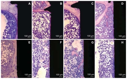
Figure 6 Histological non-decalcified ground sections of bone interface of 60 nm (A and E), 120 nm (B and F), 220 nm (C and G) patterned surfaces and reference (D and H) non-patterned surface after 7 days of implantation. Upper images (A–D) represent the histological sections in the endosteal compartment (Part A). New woven bone can be seen growing towards all the implant surfaces. Lower images (E–H) show the histological sections in the bone marrow compartment (Part B). A continuous layer of new bone formation is observed along and in direct contact with the implant surface from the upper endosteal cortical compartment (A) and the marrow bone compartment (E) for the surface patterned by 60 nm semispheres.

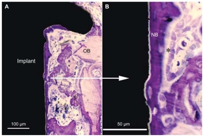
Figure 7 Histological non-decalcified ground sections of bone interface in the 60 nm group after seven days of implantation. (A) Low magnification image showing newly formed bone growing directly and along the implant surface in the endosteal compartment but also extending from the old bone onto the implant surface. (B) Higher magnification of the image (A) showing active bone formation directly on the implant surface (contact osteogenesis).
Note: *Indicates steoblast-like cell.
Abbreviations: OB, old bone; NB, new bone.
After 28 days of implantation, bone had remodeled, demonstrating a different morphology compared with the 7-day observations. One major observation in the ground sections () was the presence of a thin (30–200 μm) layer of mature, lamellar bone around and in direct contact with the surface of the implants. The layer of bone in the marrow cavity was in direct continuity with the downward (towards the marrow) extension of the endosteal bone growth, thereby creating a bone “collar” which separated the implant from the bone marrow. At this time point, no bone fragments or signs of inflammation were detected.
Figure 8 Histological non-decalcified ground sections of bone interface of 60 nm (A and E), 120 nm (B and F), 220 nm (C and G) nanopatterned surfaces and reference (D and H) non-patterned surface after 28 days of implantation. Upper images (A–D) represent the histological section in the endosteal compartment (Part A). This compartment is dominated by the downgrowth of mineralized endosteal bone in direct contact with the implant surfaces. Lower images (E–H) show histological sections in the bone marrow compartment (Part B). Mineralized bone growth along the implant in the medullary area is also observed in direct contact with the 60 nm patterned implant surface.
and show the mean percentage of BIC, BA and standard deviations between different implant groups at 7 days and 28 days. After 7 days of healing, there was no significant difference in BIC and BA between implants with nanofeatures and the control group in both endosteal (Part A) and marrow bone (Part B) compartments (P < 0.05).
Figure 9 Histomorphometry of total BIC after (A) 7 days and (B) 28 days. Notes: Bars represent mean values with marked standard deviations. Part A is the endosteal bone compartment. Part B is the bone marrow compartment. The markings indicate that the BIC was significantly higher for the 60 nm surface than for the 120 nm surface and the machined implants in both A and B compartments (P < 0.05).
Abbreviation: BIC, bone-implant contact.
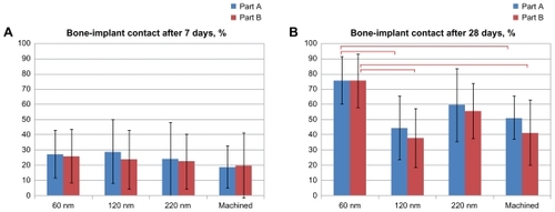
Figure 10 Histomorphometry of total BA after (A) 7 days and (B) 28 days. Notes: Bars represent mean values with marked standard deviations. Part A is the endosteal bone compartment. Part B is the bone marrow compartment. There was no significant difference between the groups at both time points (P < 0.05).
Abbreviation: BA, bone area.
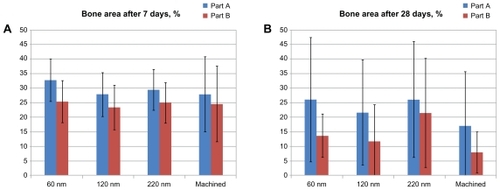
After 28 days of healing, in the endosteal (Part A) compartment, statistical analysis revealed that the BIC was significantly higher for the implant surface of the 60 nm group (76% ± 17%) than for the surface of the 120 nm group (45% ± 28%) and the control group (52% ± 24%) (P < 0.05). Similar differences were observed in the bone marrow (Part B) compartment, where statistical analysis revealed that the BIC was significantly higher for the implant surface of the 60 nm group (76% ± 16%) compared with the 120 nm group (38% ± 26%) and the control group (42% ± 27%) (P < 0.05). There were no significant differences in BIC between the surfaces of the 220 nm group and the 60 nm group in both compartments. There was also no significant difference in BA between the surfaces in nanofeature groups and the control group in both the endosteal (Part A) and marrow bone (Part B) compartments.
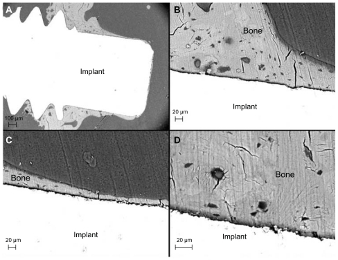
The SEM observation was in agreement with the histologic evaluation. An endosteal downgrowth from the cortex was clearly visible after 28 days of healing (). Direct BIC was observed in both the endosteal and bone marrow compartments. For the surface of the 60 nm group, the bone layer was continuous along the implant surface even at the marrow compartment. Osteocyte lacunae and canaliculi were frequently detected in the bone close to the implant surface, irrespective of surface modification.
Figure 11 Back-scattered electron micrographs of the 60 nm patterned implant after 28 days. (A) Low magnification image showing the implant and bone tissue. (B) Higher magnification of direct bone contact observed in the endosteal compartment (Part A). Osteocyte lacunae and canaliculi frequently observed close to the implant surface in the medullary compartment. (C) Mineralized bone in direct contact with the implant surface (Part B). (D) Osteocyte lacunae detected in the vicinity of the implant surface.
Discussion
The present investigation introduces a new in vivo model that could help us to understand the biological interactions of bone tissue and the nanotopography of the implant surface. This includes the choice of animal model, macroscopic implant design, compatible nanopatterning technique and adequate surface characterization methods.
Transcortical implantation in the rat tibia model has been widely used and can be regarded as a standard for studying the biological response to an alloplastic material.Citation6,Citation20 The rat is an attractive experimental model because bone turnover and resorption in a rat is several times faster than in a human.Citation21 The early signs of new bone formation appear within 7 days after implantation and complete bone formation around the implant is achieved in 28 days.Citation22,Citation23 In contrast, osseointegration in human bone is achieved 3–4 months after implantation and remodeling takes place over a 1-year period under functional conditions.Citation1,Citation24
Various implant designs have been used previously to study osseointegration in different experimental in vivo models. Commonly designed implants, such as cylindrical rods or screws, have been installed in direct contact with bone and histologic and histomorphometric analyses have focused on evaluating the adaptive response of the usually nearby, pre-existing and injured bone tissue. The limitations of these implant designs are the mechanically unstable micromovement of the cylindrical implant and the high shear and tensile stress towards the bone tissue during the installation of the screw-shaped implant which might affect the tissue response and also partly destroy the implant surface or coating. For this reason, a novel implant design was used in the present study. Threads were used in the upper part of the implant to provide good primary implant stability in direct contact with cortical bone, whereas the lower cylindrical part of the implant permitted the investigation of de novo bone formation within a well-defined healing compartment.
In this model, the implant is in contact with cortical bone, cancellous bone and bone marrow. Bone formation around an implant in the cortical compartment consists both of de novo regeneration at the implant surface via the recruitment and differentiation of mesenchymal stem cells and of the formation of bone from the surfaces of existing bone (towards the implant surface), followed by remodeling of the bone. The downgrowth of the bone in the endosteal compartment towards the implant surface reflects the distant osteogenesis. In contrast, the bone formation in the bone marrow compartment reflects the process of de novo bone formation/contact osteogenesis.Citation25 The advantage of the novel implant design used in the present investigation is its close resemblance to the clinical conditions, owing to the presence of the screws in the upper part of the implant, which provide the primary stability for the implant, and the opportunity systematically to modify the part of the cylindrical section where, at least during the early period of healing, de novo bone formation is predominant.
For the systematic variation of implant nanoscale properties, we adopted the colloidal lithography technique to produce unique, well-defined, semi-spherical protrusions on micro-rough titanium implants with controlled topography and chemistry. This process is rapid and controllable in terms of the size and density of the nanoscale features and it has been shown to be feasible for producing the semi-organized distribution of well-defined nanofeatures of various two-dimensional geometries (circular, elliptical, paired, ring-shaped) and three-dimensional shapes (cylindrical, conical, semispherical, cup-shaped, pit-shaped), as well as a wide range of materials on the planar surfaces.Citation26–Citation29 In this study, we demonstrate the applicability of colloidal lithography for the nanopatterning of rough and curved surfaces of medical implants by semispherical protrusions. The chosen size of the semispherical nano-protrusions was in the range of 60–220 nm and all the groups were coated with Ti in order to unify the experimental conditions and to distinguish topographic surface cues from chemical ones. Machined Ti implants with a Ti coating with a chemical composition analogous to the coating applied to nanobumps were used as control surfaces.
The physical qualities of titanium – high strength, toughness, durability, low density, corrosion resistance and biological compatibility – make it useful in a variety of applications.Citation30 Many other surface chemistries (eg, metallic, ceramic or organic coatings) and implant materials (eg, stainless steel, cobalt-chromium alloys, tantalum, zirconium) can be investigated with the same model system for systematic studies of surface chemical effects on cell and tissue behavior. Similarly, the suggested model system can span a wider range of topographic surface parameters than those demonstrated in this study, as summarized in .
Table 3 Properties of model implants nanostructured by colloidal lithography
The characterization of the nanopatterned implants ( and ) indicates that colloidal lithography based on polystyrene nanoparticles can be successfully used to induce well-defined nanopatterns on the complex microscale and microscale geometries of machined metallic implants, which can serve as a model system for in vivo studies. However, there are limitations to the direct use of this method to fabricate implants in commercial applications. There is a risk that nano-semispheres might be scratched off the implant surface during insertion and release polystyrene into the tissue. This risk was reduced in this study by choosing a cylindrical shape for the nanopatterned part of the implant and by drilling the insertion hole with a larger diameter than that of the cylinder, thereby minimizing the mechanical interaction of this part of the implant with the bone during implant insertion. Another consideration is that the polymeric core of the nanostructures is not resistant to high-temperature heat treatments of the final surfaces which may be desirable for sterilization or surface modification purposes (for example, to create a crystalline TiO2 layer on the outer surface). In such cases, colloidal nanoparticles of metallic or ceramic materials, such as Au, SiO2, Ti or TiO2, should be used, although they might require the development of different protocols for particle adsorption and immobilization to the implant surfaces. On the other hand, polystyrene particles have certain advantages due to commercial availability, uniform size distribution, easy shape manipulation by heat treatment and size manipulation by oxygen plasma treatment when used for the nanopatterning of model implants.
The present investigation involving nanostructured model surfaces indicates for the first time that early bone formation is dependent on the size of nanofeatures, with the exclusion of the effect of surface chemistry. The machined surface with 60 nm features (60 nm group) enhanced the bone response to the implant surface after 28 days of implantation in a rat model. The mechanism responsible for the bone-promoting effect of these specific nanoscale features was not investigated in this study. Nevertheless, the described model, in combination with additional analytical tools of cell and molecular biology, provides an opportunity for this kind of exploration under in vivo conditions. Hitherto, the majority of comparable experimental information has come from in vitro studies of cell adhesion, proliferation and differentiation on two-dimensional and three-dimensional nanostructured materials.
Previous in vitro findings reported by several investigators show that materials with a surface with nanoscale features displayed increased alkaline phosphatase synthesis and calcium mineral content in the cell layer compared with conventional materials with a microscale surface after 21 days and 28 days.Citation31,Citation32 Our findings provide evidence of the positive effects of nanotopography on osseointegration. Similarly, positive bone responses to the nanoscale topographic features of biomaterials have been reported in vivo by other researchers.Citation33 Further, short-term, experimental, in vivo studies of laser-modified titanium implants with nanoscale surface topographic features have shown a significant increase in removal torque and different fracture mechanisms.Citation34 The fact that nanostructured surfaces promoted long-term bone bonding and interface strength in vivo, as determined by coalescence between mineralized bone and the nanostructured surface and a substantial increase in removal torque, is of clinical importance.Citation35 Furthermore, a previous in vivo study of electropolished titanium implants with nanosized hydroxyapatite particle modification compared with a non-coated control showed greater bone contact for the modified surface after 4 weeks of healing.Citation36 Acid-etched microtopography with irregular, discrete, 20–40 nm hydroxyapatite particles has also been reported to enhance the strength and direct bone bonding of osseointegration.Citation33
Another experiment with a hydrofluoric-acid-treated, sand-blasted titanium surface produced an approximately 100 nm structural modification of a titanium surface and this may be related to the enhanced osteoblastic differentiation occurring on the surface.Citation37
Nevertheless, in these latter experimental studies, the shape, size, chemistry and distribution of the nanostructure differ between the technologies. Moreover, in each of these techniques, many variables (chemistry, porosity and crystallinity) influence molecular and cellular interactions with surface structures and it is difficult to draw conclusions and formulate general principles for nanostructured surfaces.
Several interpretations of the effect of nanofeatures on bone response have been put forward.Citation38 One hypothesis about the origin of this kind of effect is that nanoscale topographic features in the <100 nm region more closely mimic the natural constituents of bone (hydroxyapatite crystals and collagen) than a surface with microscale roughness,Citation39 which is in agreement with our findings in this study, showing that 60 nm semispheres improved bone implant contact in comparison with larger (120 nm, 220 nm) nanostructures or unmodified machined implants (control group). A second hypothesis suggested that altering the surface area by adding semispherical nanostructures to the microscale topography of machined implants would increase their wettability by blood and the spreading and binding of fibrin and matrix proteins and would increase the cell attachment area.Citation40,Citation41 Our present study contradicts this hypothesis, because both the most hydrophilic surface (patterned by 120 nm semispheres) and the implant with the largest surface area (patterned by 220 nm semispheres) had a lower bone response compared with the surface patterned by 60 nm protrusions of intermediate wettability and surface area.
The impact of nanotopography on increased bone formation might also be due to the effect of feature density.Citation42 The surface modification of the titanium implant with 60 nm semispheres had a nanofeature density that was at least twice as high compared with the implants patterned by the 120 nm and 220 nm semispheres. This may represent a larger quantity of surface cues per interacting cell and thus explain the tendency towards enhanced bone contact with the 60 nm patterned implants.
A further hypothesis suggested that the surface curvature of nanofeatures has an influence on protein binding and/or induces dramatic changes in cell behavior, including morphology, proliferation and differentiation. Several studies have shown that interaction between specific proteins and smaller nanoparticles may be due to a larger surface curvature.Citation43,Citation44 In fact, the 60 nm semispheres used in this study had the largest local surface curvature and this property might therefore be responsible for the observed increase in BIC after 28 days.
It is anticipated that further studies involving model systems with variable nanofeature densities with fixed size (curvature) or variable size but fixed density will contribute to the further identification and understanding of the nanoscale topographical properties that affect in vivo bone formation and bonding strength.
Conclusions
This study presents a novel in vivo model system consisting of the chemically and geometrically well-defined semispherical surface nanoprotrusions of variable size that can be applied to complex screw-shaped implants in the presence of microscale background roughness. After insertion in bone, a significant enhancement in bone formation was detected on Ti implant surfaces modified by 60 nm semispheres after 28 days of healing. The results suggest that this effect might be related to (1) size similarity to the mineral part of the natural bone matrix, (2) a higher density distribution of nanofeatures and (3) a larger surface curvature of the 60 nm semispherical nanostructures in comparison to the 120 nm and 220 nm semispherical nanostructures. The model can be adapted for the systematic and independent variation of chemical and topographical surface properties and therefore enables in-depth analysis of material nanoscale interactions with bone.
Disclosure
The authors report no conflict of interest in this work.
Acknowledgments
This work was supported by the BIOMATCELL VINN Excellence Center of Biomaterials and Cell Therapy and Chalmers Area of Advance-Materials Science. Stefan Gustafsson, Chalmers University of Technology, and Lena Emanuelsson, University of Gothenburg, are gratefully acknowledged for supplying the TEM images of nano-semispheres and for surgical assistance respectively.
References
- BrånemarkPIOsseointegration and its experimental backgroundJ Prosthet Dent19835033994106352924
- GeorgeZAlbrektssonTBakerGOsseointegration. On continuing synergies in surgery, prosthodontics and biomaterialsNew Malden, UKQuintessence Publishing Co Ltd2008
- KimTIJangJ-HKimHWKnowlesJCKuYBiomimetic approach to dental implantsCurr Pharm Des200814222201201118781972
- MendonçaGMendonçaDBAragãoFJCooperLFAdvancing dental implant surface technology – from micron – to nanotopographyBiomaterials200829283822383518617258
- AlbrektssonTSennerbyLWennerbergAState of the art of oral implantsPeriodontol 2000200847152618412571
- PearceAIRichardsRGMilzSSchneiderEPearceSGAnimal models for implant biomaterial research in bone: a reviewEur Cell Mater20071311017334975
- HuRLinCYShiHYA novel ordered nano hydroxyapatite coating electrochemically deposited on titanium substrateJ Biomed Mater Res A200780368769217109412
- BarrereFSnelMMvan BlitterswijkCAde GrootKLayrollePNano-scale study of the nucleation and growth of calcium phosphate coating on titanium implantsBiomaterials200425142901291014962569
- YaoCWebsterTJAnodization: a promising nano-modification technique of titanium implants for orthopedic applicationsJ Nanosci Nanotech200669–1026822692
- OgawaTSaruwatariLTakeuchiKAitaHOhnoNTi nanonodular structuring for bone integration and regenerationJ Dent Res200887875175618650547
- ChenXMaoSSSynthesis of titanium dioxide (TiO2) nanomaterialsJ Nanosci Nanotechnol20066490692516736747
- WebsterTJNanotechnology for the regeneration of hard and soft tissuesSingaporeWorld Scientific Publishers2007
- HanarpPSutherlandDGoldJKasemoBNanostructured model biomaterial surfaces prepared by colloidal lithographyNanostructure Materials199912429432
- RasbandWSImageJBethesda, MDUS National Institutes of Health Available from: http://rsb.info.nih.gov/ijAccessed December 6, 2011
- LenthRVJava Applets for power and sample size [computer software] Available from: http://stat.uiowa.edu/~rlenth/PowerAccessed December 6, 2011
- WermelinKSuskaFTengvallPThomsenPAspenbergPStainless steel screws coated with bisphosphonates gave stronger fixation and more surrounding bone. Histomorphometry in ratsBone200842236537118055289
- WenzelRNResistance of solid surfaces to wetting by waterInd Eng Chem193628988994
- QuereDRough ideas on wettingPhysica A: Statistical Mechanics and Its Applications20023131–23246
- IshinoCOkumuraKWetting transitions on textured hydrophilic surfacesEur Phys J E Soft Matter200825441542418431542
- DhertWJThomsenPBlomgrenAKIntegration of press-fit implants in cortical bone: a study on interface kineticsJ Biomed Mater Res19984145745839697030
- BalloAMBrokeJEvaluation of implant osseointegration in small laboratory animalsBalloAMImplant Dentistry Research Guide: Basic, Translation, and Clinical ResearchHauppauge, NYNova Publishers2012151176
- FutamiTFujiiNOhnishiHTissue response to titanium implants in the rat maxilla: ultrastructural and histochemical observations of the bone-titanium interfaceJ Periodontol200071228729810711620
- MuraiKTakeshitaFAyukawaYLight and electron microscopic studies of bone-titanium interface in the tibiae of young and mature ratsJ Biomed Mater Res1996304523338847361
- BrånemarkPIHanssonBOAdellROsseointegrated implants in the treatment of the edentulous jaw. Experience from a 10-year periodScand J Plast and Reconstr Surg Suppl1977161132356184
- DaviesJEUnderstanding peri-implant endosseous healingJ Dent Educ200367893294912959168
- DuKWathuthanthriIMaoWXuWChoiCHLarge-area pattern transfer of metallic nanostructures on glass substrates via interference lithographyNanotechnology2011222828530621642762
- FredrikssonHAlaverdyanYDmitrievCHole–mask colloidal lithographyAdvanced Materials2007192342974302
- ChenYPépinANanofabrication: conventional and nonconventional methodsElectrophoresis20012218720711288885
- KosiorekAKandulskiWGlaczynskaHGiersigMFabrication of nanoscale rings, dots, and rods by combining shadow nanosphere lithography and annealed polystyrene nanosphere masksSmall20051443944417193469
- BrunetteDMTengvallPTextorMThomsenPTitanium in medicine: material science, surface science, engineering, biological responses, and medical applicationsBerlinSpringer Verlag200187144
- MyllymaaSKaivosojaEMyllymaaKAdhesion, spreading and osteogenic differentiation of mesenchymal stem cells cultured on micropatterned amorphous diamond, titanium, tantalum and chromium coatings on siliconJ Sci Mater Med2010211329341
- DalbyMJGadegaardNTareRThe control of human mesenchymal cell differentiation using nanoscale symmetry and disorderNat Mater2007612997100317891143
- OrsiniGPiattelliMScaranoARandomized, controlled histologic and histomorphometric evaluation of implants with nanometer-scale calcium phosphate added to the dual acid-etched surface in the human posterior maxillaJ Periodontol200778220921817274708
- BrånemarkREmanuelssonLPalmquistAThomsenPBone response to laser-induced micro- and nano-size titanium surface featuresNanomedicine20117222022721059406
- PalmquistAEmanuelssonLBrånemarkRThomsenPBiomechanical, histological and ultrastructural analyses of laser micro- and nanostructured titanium implant after 6 months in rabbitJ Biomed Mater Res B Appl Biomater201197228929821394900
- MeirellesLArvidssonAAnderssonMNano hydroxyapatite structures influence early bone formationJ Biomed Mater Res A200887229930718181110
- GuoJPadillaRJAmbroseWDe KokIJCooperLFThe effect of hydrofluoric acid treatment of TiO2 grit blasted titanium implants on adherent osteoblast gene expression in vitro and in vivoBiomaterials200728365418542517868850
- BettingerCJLangerRBorensteinJTEngineering substrate topography at the micro- and nanoscale to control cell functionAngew Chem Int Ed Engl200948305406541519492373
- ThomasJTAyadSGrantMECartilage collagens: strategies for the study of their organisation and expression in the extracellular matrixAnn Rheum Dis19945384884967944631
- SchwarzFWielandMSchwartzZPotential of chemically modified hydrophilic surface characteristics to support tissue integration of titanium dental implantsJ Biomed Mater Res B Appl Biomater200988254455718837448
- KarabudaZCAbdel-HaqJArisanVStability, marginal bone loss and survival of standard and modified sand-blasted, acid-etched implants in bilateral edentulous spaces: a prospective 15-month evaluationClin Oral Implants Res201122884084921198901
- Cavalcanti-AdamEAVolbergTMicouletACell spreading and focal adhesion dynamics are regulated by spacing of integrin ligandsBiophys J20079282964297417277192
- AsuriPBaleSSKarajanagiSSKaneRSThe protein-nanomaterial interfaceCurr Opin Biotechnol200617656256817015011
- LundqvistMSethsonIJonssonBHProtein adsorption onto silica nanoparticles: conformational changes depend on the particles’ curvature and the protein stabilityLangmuir20042024106391064715544396