 ?Mathematical formulae have been encoded as MathML and are displayed in this HTML version using MathJax in order to improve their display. Uncheck the box to turn MathJax off. This feature requires Javascript. Click on a formula to zoom.
Abstract
In this study, we have generated terahertz (THz) frequency by a novel design of microring resonators for medical applications. The dense wavelength-division multiplexing can be generated and obtained by using a Gaussian pulse propagating within a modified PANDA ring resonator and an add/drop filter system. Our results show that the THz frequency region can be obtained between 40–50 THz. This area of frequency provides a reliable frequency band for THz pulsed imaging.
Introduction
Nonlinear terahertz (THz) radiation is the electromagnetic spectrum which ranges from 30 THz to 100 GHz. It covers the region away from microwaves via mid to beyond infrared. Formerly, bulky and expensive equipment such as free electron lasers or the alternative employment of thermal sources produced weak, incoherent radiation. THz radiation gives rise to rotational and vibrating excitation of some biological molecules. THz radiation has also been used in tissue with differentiating abilities.Citation1 There is an increasing tendency towards THz technology for the next wave of noninvasive biomedical instruments.Citation2,Citation3 THz pulse has many properties that could encourage the use of THz pulsed imaging (TPI) as a medical imaging tool. Moreover, THz waves are useful for the analysis of histopathological diagnosis, without any staining process.Citation4 Rayleigh scattering of electromagnetic radiation increases with the inverse of the wavelength to the fourth power. However, there is no ionization hazard for biological tissue.Citation5 TPI is a new technique based on broadband pulses of electromagnetic radiation of THz frequencies.Citation6,Citation7 Contrast images can be obtained for different degrees of THz wave absorption for normal tissues, such as muscles, fatty tissue and cartilage, as well as cancer tissue. We can obtain THz images using a microring resonator (MRR) in a wide range of wavelengths.Citation8,Citation9 The THz pulse interacts with the sample in reflection or transmission modes. The modified pulse is recorded as a time-series. The spectra information from THz pulses has been used to distinguish different types of soft tissues, such as muscle, fat, and kidney tissues.Citation10,Citation11
Methodology and results
In order to achieve a wide band frequency carrier, we propose a novel system consisting of MRRs for many communication applications such as a wireless THz communication system and faster data transfer, which requires higher carrier frequencies.Citation12 In this paper, we use MRRs made of InGaAsP/InP material to enhance the channels of the frequency band for implementation in medical imaging.Citation13
The transfer function of the system uses Gaussian beam, described by EquationEquation 1(1) .Citation14
Here A1 is the amplitude of the optical field and t is the time for phase shift with frequency shift of ω0. The optical outputs from the first and second ring resonators are given by EquationEquations 2(2) and Equation3
(3) .Citation15,Citation16
Here κ is the coupling coefficient, and K represents the wave number in vacuum. γ is the fractional coupling intensity loss. L1 and L2 are circumferences of the first and second rings. Exp(−αL/2) shows the roundtrip loss coefficient and α is the waveguide loss. For the PANDA system, the output optical fields from right and left rings are expressed by EquationEquations 4(4) and Equation5
(5) .
Here, ER and EL are the outputs from the right and left rings of the PANDA system. The interior output fields of E1, E2, E3, and E4 are shown in EquationEquations 6(6) –Equation9
(9) .
Therefore, the final equations for drop port and throughput power are given in EquationEquations 10(10) –Equation13
(13) .
where Pt and Pd represent the output powers of the throughput and drop port, respectively.Citation14,Citation15
In this work we use a Gaussian beam as an input power to the proposed system. The new design of the system is illustrated in . In this case the Gaussian pulse with a center wavelength of 1.3 μm, pulse width of 20 ns, and power of 1 W, is an input into the system as shown in . The parameters used are R1 = 5 μm (radius of first ring), R2 = 3 μm (radius of second ring), RL = 1 μm (radius of left ring of PANDA), RR = 1 μm (radius of right ring of PANDA), R = 3 μm (radius of centered ring of PANDA), Aeff = 0.10–0.25 μm.Citation2 Some fixed parameters such as nonlinear refractive index, n0 = 3.34 (InGaAsP/InP)Citation17 and intensity attenuation coefficient, α = 0.2 dBmm−1 have been selected for this system. The coupler intensity loss is γ = 0.1. The coupling coefficient of the MMR varies from 0.1–0.98. The nonlinear refractive index is n2 = 2.2 × 10⁻¹⁷.
Figure 1 Schematic of two microring resonators coupled into a PANDA system.
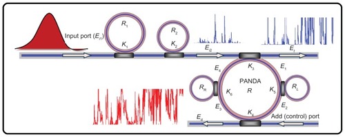
Figure 2 Result of the outputs from two ring resonators with centre wavelength at 1.3 μm: (A) the input Gaussian pulse, (B) the chaotic signal generation, (C) the amplified and filtering signals.
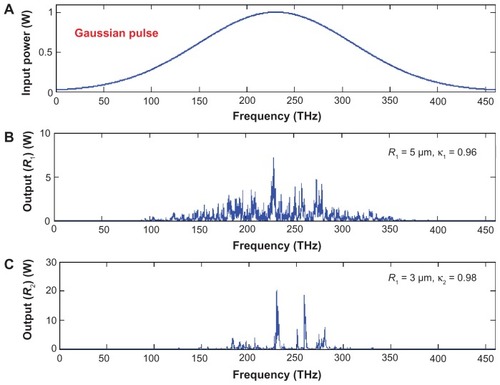
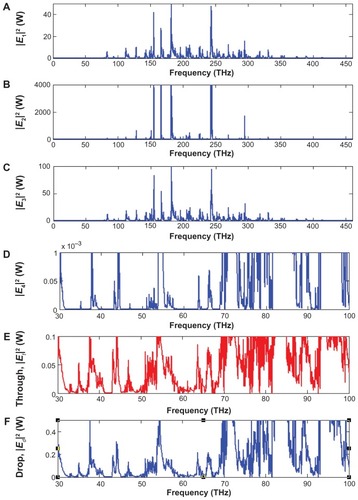
The input pulse is sliced to a smaller signal through the spectrum shown in . The light pulse can be chopped into discrete signals and amplified in the first ring, where more signal amplification is obtained by the second ring (smaller ring). The output signals from the second ring resonator are inputs into the PANDA system. Output signals of the PANDA system are simulated and shown in . show the best region of frequency, which can be seen at the range of 40–50 THz. In practice, the channel frequency can be increased by using the system. Finally, the required signals can be obtained via the PANDA system.
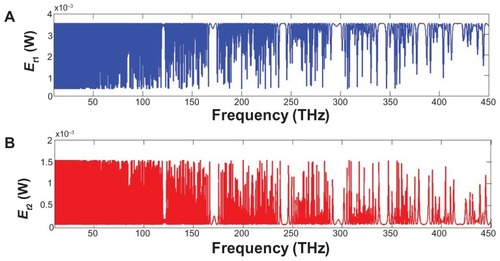
Figure 3 Simulation results of the light pulse generated by the PANDA system at center wavelength of 1.3 μm, where (A) |E1|2, (B) |E2|2, (C) |E3|2, (D) |E4|2, (E) |Ed|2, and (F) |Et|2 are output powers inside a PANDA system.
The output signals from the PANDA system are inputs to the add/drop filter system in order to cancel out noisy chaotic signals. To retrieve the signals from the chaotic noise, we suggest the use of add/drop filters with proper parameters. Two complementary optical circuits of the MRR add/drop filter can be illustrated by EquationEquations 14(14) and Equation15
(15) .Citation17
where Et1 and Et2 represent the optical fields of the throughput and drop port, respectively. β = kneff is the propagation constant, neff is the effective refractive index of the waveguide, L = 2πR is the circumference of the ring, and R is the radius of the ring. For simplification, we define the phase constant as φ = βL. Chaotic noise cancellation and required signals can be obtained by using the particular parameters of the add/drop device. κ1 and κ2 are coupling coefficients of the add/drop filters, κn = 2π/λ is the wave propagation number for a vacuum, where the waveguide loss is α = 0.2 dB/mm. The fractional coupler intensity loss is γ = 0.1. For the add/drop filter device, the nonlinear refractive index is neglected.
We used an add/drop filter system with a radius of 10 μm to determine the free spectral range, the number of channels and bandwidth as shown in . shows the simulation results where represent the throughput and drop port outputs of the system, respectively.
Figure 4 Schematic of an add/drop filter system for area frequency selection.
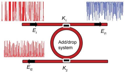
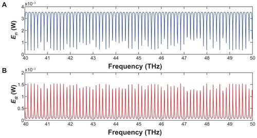
Figure 5 Simulation results of the channel frequency light pulse generated by the add/drop filter system at the center wavelength of 1.3 μm for Gaussian pulse: (A) system throughput, (B) system drop port.
As demonstrated in , generated dense wavelength-division multiplexing from the proposed configuration of ring resonators are involved in the THz region, which provides a reliable frequency band for medical applications, especially for THz imaging. The main advantage of THz imaging is its diagnostic capabilities.Citation11 These obtained pulses are also useful for analysis of the histopathological diagnosis, without any staining process.Citation6
Figure 6 Expansion of simulation result of the channel frequency light pulse generated by the add/drop filter system.
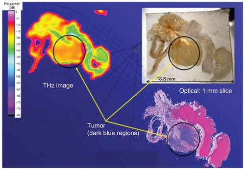
To date, imaging spectroscopy is used only for small areas.Citation3,Citation4 THz imaging exactly reflects the tissue situation, for instance tumor, nontumor tissues, tissue degeneration, and fibrosis. The THz image shows significantly reduced absorption of THz radiation in this region compared with normal tissue, which suggests its usefulness for detecting tumors (). Contrast images associated with different degrees of absorption of THz waves have been obtained for normal tissues, such as muscles, fatty tissue, and cartilage, as well as for cancer tissue. We could obtain THz images of large areas from an MRR in a wide range of wavelengths.Citation8,Citation10,Citation11
Figure 7 Prostate section with tumor tissue as imaged with terahertz, optical, and staining techniques.
Conclusion
In this study, a new MRR design has been introduced, which provides the best frequency band when the input Gaussian pulse is used. This system consists of a series of MRRs connected to a PANDA system. Using the proposed system, multifrequency bands can be generated and simultaneously linked to an add/drop filter where it is suitable for analysis of the histopathological diagnosis. The results show the frequency band region lies between 40–50 THz. This range provides a reliable frequency band for medical purposes, especially in THz imaging.
Acknowledgments
We would like to thank the Institute of Advanced Photonics Science, Nanotechnology Research Alliance, Universiti Teknologi Malaysia (UTM) and King Mongkut’s Institute of Technology (KMITL), Thailand for providing the research facilities. This research work has been supported by SLAI IDF financial support from UTM. The authors report no conflicts of interest in this work.
References
- MittlemanMDJacobsonRHNussMCT-ray imagingIEEE J Sel Top Quant Electron19962679692
- IglesiasEJSmithAWKaplanSGA sensitive, spatially uniform photo-detector for broadband infrared spectrophotometryAppl Opt2008472430243618449309
- ArnoneDCieslaCPepperMTerahertz imaging comes into viewPhys World2000133540
- KnoblochPSchildknechtCKleine-OstmannTMedical THz imaging: An investigation of histo-pathological samplesPhys Med Biol2002473875388412452579
- FitzgeraldABerryEZinovevNWalkerGCSmithMAChamberlainJMAn introduction to medical imaging with coherent terahertz frequency radiationPhys Med Biol200247R678411996068
- HuBNussMImaging with terahertz wavesOpt Lett1995201716171819862134
- ZhangXGeneration and detection of pulsed microwave signals by THz optoelectronicsProceedings of 1997 SBMO/IEEE MTT-S International Microwave and Optoelectronics Conference, 1997. Linking to the Next CenturyNatal, BrazilAugust 11–14, 19971215220
- NishizawaJISasakiTSutoKTHz imaging of nucleobases and cancerous tissue using a GaP THz-wave generatorOpt Comm20052441–6469474
- WallaceVPTadayPFFitzgeraldAJTerahertz pulsed imaging and spectroscopy for biomedical and pharmaceutical applicationsFaraday Discuss200412625526314992411
- FitzgeraldAJWallaceVPJimenez-LinanMLTerahertz pulsed imaging of human breast tumorsRadiology200623953354016543586
- NakajimaSHoshinaHYamashitaMOtaniCMiyoshiNTerahertz imaging diagnostics of cancer tissues with a chemometrics techniqueAppl Phys Lett200790041102
- UdomariyasapPNoppanakeepongSMitathaSYupapinPPTHz light pulse generation and storage within an embedded optical waveguide systemJ Nonlinear Opt Phys201019303310
- GroverRAbsilPPVanVVertically coupled GaInAsP-InP microring resonatorsOpt Lett20012650650818040367
- JuleangPPhongsanamPMitathaSYupapinPPPublic key suppression and recovery using a PANDA ring resonator for high security communicationOpt Eng201150035002
- YupapinPPVanishkornBMathematical simulation of light pulse propagating within a microring resonator system and applicationsAppl Math Model20113517291738
- AmiriISAfroozehABahadoranMSimulation and analysis of multisoliton generation using a PANDA ring resonator systemChinese Phys Lett201128104205
- PiyatamrongBKulsiriratKTechitdheeraWMitathaSYupapinPPDynamic potential well generation and control using double resonators incorporating an add/drop filterMod Phys Lett B20102430713080