 ?Mathematical formulae have been encoded as MathML and are displayed in this HTML version using MathJax in order to improve their display. Uncheck the box to turn MathJax off. This feature requires Javascript. Click on a formula to zoom.
Abstract
Background
The objective of this investigation was to develop a new class of antibacterial material in the form of nanofibers coated with silver nanoparticles (AgNPs) using a modified coaxial electrospinning approach. Through manipulation of the distribution on the surface of nanofibers, the antibacterial effect of Ag can be improved substantially.
Methods
Using polyacrylonitrile (PAN) as the filament-forming polymer matrix, an electrospinnable PAN solution was prepared as the core fluid. A silver nitrate (AgNO3) solution was exploited as sheath fluid to carry out the modified coaxial electrospinning process under varied sheath-to-core flow rate ratios.
Results
Scanning electron microscopy and transmission electron microscopy demonstrated that the sheath AgNO3 solution can take a role in reducing the nanofibers’ diameters significantly, a sheath-to-core flow rate ratio of 0.1 and 0.2 resulting in PAN nanofibers with diameters of 380 ± 110 nm and 230 ± 70 nm respectively. AgNPs are well distributed on the surface of PAN nanofibers. The antibacterial experiments demonstrated that these nanofibers show strong antimicrobial activities against Bacillus subtilis Wb800, and Escherichia coli dh5α.
Conclusion
Coaxial electrospinning with AgNO3 solution as sheath fluid not only facilitates the electrospinning process, providing nanofibers with reduced diameters, but also allows functionalization of the nanofibers through coating with functional ingredients, effectively ensuring that the active antibacterial component is on the surface of the material, which leads to enhanced activity. We report an example of the systematic design, preparation, and application of a novel type of antibacterial material coated with AgNPs via a modified coaxial electrospinning methodology.
Introduction
One of the aims of nanotechnology is the control of structures at the nanometer level. Such nanoengineering can lead to significantly modified, and often enhanced, properties. Citation1 Electrospinning is a simple and straightforward technology for generating nanofibers. The popularity of this system is not only due to its easy implementation, versatility with regard to potential ingredient materials, but also its convenience in obtaining nanostructures.Citation2–Citation6
As a simple and straightforward “top–down” process, electrospinning has the unique capability of copying structures from the macro world to products at the micro/ nanoscale directly.Citation7–Citation10 For example, electrospinning can easily duplicate the structure of macro jet devices (as concentric and side-by-side spinnerets) to generate products with special nanostructures such as core-sheath and side-by-side nanofibers.Citation7–Citation10 In particular coaxial electrospinning, in which a concentric spinneret can accommodate two different liquids, is regarded as one of the most significant breakthroughs in the field.Citation11–Citation13 It has been applied in controlling secondary structures of nanofibers, encapsulating drugs or biological agents into the polymeric nanofibers, fabricating polymeric microtubes, preparing nanofibers from materials that lack filament-forming properties, and enclosing functional liquids within the fiber matrix.Citation14–Citation18 In traditional coaxial electrospinning, the sheath solution acts as a guide and surrounds the core material, which means that the sheath fluids must be electrospinnable and have enough viscosity to overcome the interfacial tension between the two solutions through “viscous dragging” and “contact friction” for a successful coaxial process.Citation17,Citation18
More recently, a modified process based on coaxial electrospinning was reported, in which only unspinnable solvents were used as sheath fluids. This process was exploited to manipulate nanofiber diameters and control the size of self-assembled nanoparticles generated from the fibers, to prepare fibers from concentrated polymer solutions previously thought to be unspinnable, and to further decrease the nanofiber diameter to take advantage of the resultant high surface area and porosity in the nonwoven mats.Citation19–Citation22 In all these investigations, sheath solvents act as a useful tool, permitting core electrospun fluid jets to be subjected to longer periods of electrical drawing. Later advances involved adding surfactants and salts to the sheath fluids so as to manipulate the conductivity and surface tension of sheath solutions for a better coaxial electrospinning process and produce nanofibers with even smaller diameters and a smooth surface morphology.Citation23–Citation29 However in all the above-mentioned reports, the modified coaxial electrospinning processes generated nanofibers with improved quality in terms of nanofiber diameter, diameter distribution, as well as nanofiber morphology, but no attempts were made to modify the nanofibers so as to improve their functionality and enhance their nascent efficiency.
Silver (Ag) ions, colloidal silver nanoparticles (AgNPs) and silver-containing compounds are well documented as effective antiseptics for controlling broad-spectrum microbes and antibiotic-resistant bacteria in vitro.Citation30–Citation42 Electrospun Ag-containing polymer nanofiber mats have been intensively investigated for potential biomedical applications, such as wound-dressing materials, body wall repairs, augmentation devices, tissue scaffolds, and antimicrobial filters.Citation43–Citation47 However, all the nanofibers were prepared using a single fluid electrospinning approach involving codissolving solutions of polymer and silver nitrate (AgNO3). This was then followed by reduction of the incorporated Ag+ to AgNPs so as to take advantage of the unique property of nanofibers such as huge surface, small diameter, high porosity, and a three-dimensional continuous web structure. Although the prepared Ag-containing polymer nanofibers were demonstrated to provide the desired performance, most of the Ag was wasted as it was buried in the inner part of the nanofibers. It was proposed that if the AgNPs can be distributed on the surface of the nanofibers, the efficacy of the formulated material should be improved substantially.Citation48–Citation50
Polyacrylonitrile (PAN) is a synthetic, semicrystalline organic polymer resin, with the linear formula (C3H3 N)n. It is a versatile polymer used to produce a large variety of products including ultrafiltration membranes, hollow fibers for reverse osmosis, fibers for textiles, oxidized flame retardant fibers, and carbon fiber.Citation51 Based on its wide-ranging applications and good electrospinnability, PAN was selected as the filament-forming matrix. The PAN nanofibers with AgNPs distributed on their surface were produced using a modified coaxial electrospinning process, which involved using only AgNO3 solution as the sheath fluid to facilitate the electrospinning process and render the new functions of the nanofibers.
Materials and methods
Materials
PAN powders (M̄w = 80,000) were purchased from Jinshan Petrochemistry Co, Ltd (Shanghai, China). N, N-dimethylacetamide (DMAc) and AgNO3 were obtained from the Sinopharm Chemical Reagent Co, Ltd (Shanghai, China). All reagents were analytical grade and used without further purification. Water was double distilled just before use.
Coaxial electrospinning process
Preparation of spinning solutions
A solution of 15% (w/v) PAN in DMAc was used as core fluid. Pure DMAc and a concentration of 10% (w/v) AgNO3 in DMAc were employed as sheath fluids. Other conditions for fabrication of different nanofibers are listed in .
Table 1 Experimental parameters for the fabrication nanofibers
The concentric spinneret was designed and fabricated in-house and used to carry out coaxial electrospinning. Two syringe pumps (KDS100 and KDS200; Cole-Parmer®, Chicago, IL) were employed to drive the sheath and core fluids according to the parameters in . A metal clip was used to connect the spinneret with the high voltage supply (Shanghai SuTe Electrical Co, Ltd, Shanghai, China) and the applied voltage was 18 kV. The nanofibers were collected on a metal collector wrapped with aluminum foil and kept at a fixed distance of 20 cm away from the needle tip of the spinneret. The coaxial processes were recorded using a digital video recorder (PowerShot A640; Canon, Tokyo, Japan) under magnifications of 11×. The electrospun nanofibers were exposed to 254 nm ultraviolet light for 24 hours to reduce the Ag+ to AgNPs.
Characterization
The morphology of the core-sheath nanofibers was assessed using a Quanta FEG450 scanning electron microscope (SEM; FEI Corporation, Eindhoven, The Netherlands). The average fiber diameter was determined by measuring diameters of nanofibers over 100 points from field emission SEM images using Image J software (National Institutes of Health, Bethesda, MD). The elemental composition of the samples was analyzed by an energy-dispersive spectrometer EDAX (EDS; EDAX Inc, Draper, UT), [software; IE300X, Oxford, UK] attached to the SEM.
Transmission electron microscopy (TEM) images of the samples were recorded on a JEM 2100F field emission TEM (JEOL, Tokyo, Japan). TEM samples were collected by fixing a lacy carbon-coated copper grid on the collector.
Antibacterial test
The in vitro antibacterial activities of PAN nanofibers F2, F3, and F4 were examined according to enumeration by the plate count method described previously.Citation52,Citation53 The following microorganisms were used: Gram-positive Bacillus subtilis (Wb800) and Gram-negative Escherichia coli dh5α (E. coli dh5α). Briefly, sterilized Luria–Bertani (LB) broth was measured (5 mL) into an Erlenmeyer flask. Sixty mg PAN nanofibers were introduced into the LB broth solution, which contained approximately 1.5 × 10⁵ colony-forming units (CFU) of Wb800 and E. coli dh5α, respectively. The mixtures were cultured at 37°C in a shaking incubator for 12 hours. One hundred microliters of each of these cell solutions was seeded onto LB agar using a surface spread plate technique. The plates were incubated at 37°C for 24 hours. The numbers of bacterial colonies (CFU) were counted.
Pure phosphate-buffered saline (PBS) and AgNO3 were also tested as blank control and positive control, respectively. One hundred microliters of each of these cell solutions was seeded onto LB agar using a surface spread plate technique. The plates were incubated at 37°C for 24 hours. The numbers of bacterial colonies (CFU) were counted. The counts were used to calculate the surviving number of bacteria. The antibacterial efficacy (ABE in %) of the specimen was calculated according to the following equation:
where Vc and Vt stands for the numbers of viable bacterial colonies of the blank control (pure PBS buffer added) and test specimen, respectively. All the experiments were repeated six times and the results are presented as mean values.
Results and discussion
Modified coaxial electrospinning
A schematic diagram of the coaxial electrospinning process is shown in . Two syringe pumps were employed to drive the sheath and core fluids respectively. The nanofibers are collected on a plate and the coaxial processes can be recorded using a digital video recorder. The self-made concentric spinneretCitation20 used to carry out the modified coaxial electrospinning is shown in . The upper surface of the core capillary was indented 1.0 mm from the tip of the sheath capillary, and this facilitates easier envelopment of the core spinning solution by the outer solvent. The system differs from conventional coaxial spinnerets in which the tips of the inner and the outer capillary are coplanar or the tips of the inner capillary slightly project out the tips of the outer capillary.
Figure 1 Schematic diagram of the modified coaxial electrospinning process (A) and the homemade concentric spinneret (B).
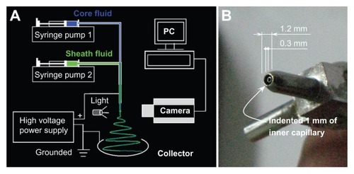
The critical voltage applied to a fluid to initiate Taylor cone formation and the straight thinning jet (Vc) has a close relationship with the diameter of the sheath part of the concentric spinneret:Citation54
where Vc is the critical voltage for a jet emanating from the meniscus tip, d is the electrode separation, ɛ is the permittivity, γ is the surface tension, and R is the principal curvature of the liquid meniscus. A low diameter spinneret orifice gives a high value of R, and thus only a small Vc is needed to initiate electrospinning. The self-made spinneret used in this work has outside and inner diameters of 1.2 and 0.3 mm respectively, facilitating the coaxial electrospinning process.
A digital picture of the coaxial electrospinning process is shown in . shows the connection of power supply with the spinneret and the sheath and core fluids. This modified coaxial electrospinning differs from the traditional coaxial process in that the core fluid was the protagonist whereas the sheath fluid played a supporting role for smoothing and stabilizing the overall process. It also differs from the traditional single fluid process as the formation of the Taylor cone, the thinning of straight jet and part of the instability region would occur in the surrounding solvent, not the atmosphere.
Figure 2 Digital pictures of the modified coaxial process: (A) A digital picture shows arrangement of apparatus; (B) The connection of power supply with the spinneret and the sheath and core fluids; (C and D) A typical fluid jet trajectory (taken with a magnification of 12×, a core and sheath flow rates of 1.0 and 0.2 mL/hour and a fiber collection distance of 20 cm) under a high voltage of 15 and 18 kV, respectively.
Abbreviation: PAN, Polyacrylonitrile.
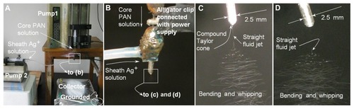
exhibits a typical fluid jet trajectory when core and sheath flow rates of 1.0 and 0.2 mL/hour were taken under a high voltage of 15 kV. A typical electrospinning process can be discerned according to the following stages: (1) fluid charging and the formation of the compound Taylor cone-jet, (2) thinning of the straight fluid jet, (3) onset and growth of jet instabilities (ie, the bending and whipping region) and random collections of the nanofibers. When the applied voltages were further raised to 18 kV, the compound Taylor cone shrank into the indented region of the outer capillary of spinneret and cannot be discerned in the picture (). However, the straight fluid jets, the bending and whipping of the fluid jets under the electrical field are all similar as those in . A higher applied voltage always leads to finer nanofibers, thus a voltage of 18 kV was selected as the final value for producing Ag-coating PAN nanofibers.
Morphology
shows the SEM images of the prepared four types of nanofibers. All the nanofibers have uniform structures without beads-on-a-string morphology owing to the good electrospinnability of the core PAN solutions. However, PAN nanofibers from the traditional single fluid electrospinning F1 have very rough surfaces, along with the largest average diameters and broadest distributions (750 ± 160 nm; ).
Figure 3 SEM images of PAN nanofibers prepared using different processes: (A) surface morphologies and diameter distribution of nanofibers F1 from single fluid electrospinning; (B) surface morphologies and diameter distribution of nanofibers F2 from a modified coaxial process with only DMAc as sheath fluid; (C and D) surface morphologies and diameter distribution of nanofibers F3 and F4 from a modified coaxial process with AgNO3 solution as sheath fluid, respectively. The scale bars in the insets of (C and D) represent 500 nm. (E and F) are TEM images of nanofibers F3 and F4, respectively.
Abbreviations: AgNO3, silver nitrate; DMAc, N,N-dimethylacetamide; PAN, polyacrylonitrile; SEM, scanning electron microscopy; TEM, transmission electron microscopy.
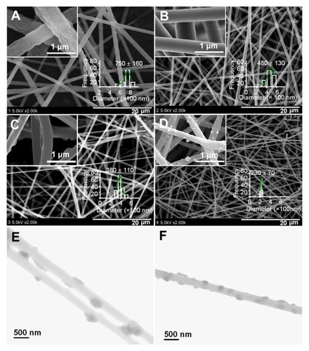
When the coaxial electrospinning was taken with DMAc as the sheath fluid, the traditional Taylor cone-air and fluid jet-air interfaces have become Taylor cone-solvent and fluid jet-solvent interfaces. As a result, the formation of the cone-jet, the thinning of the straight jet and partial bending and whipping were different when compared to the traditional system conducted in air. The presence of sheath DMAc in the process would not only let the PAN fluid jet be subjected to a longer period of electrical drawing, but also provide stable and robust conditions for the solvent in the PAN fluid jet to evaporate. Correspondingly, the modified process generated nanofibers F2 with smaller diameters, narrower distributions (480 ± 130 nm), and smooth surface morphology ().
When AgNO3 solution was employed as sheath fluid, the nanofiber (F3) diameters and their distributions () even became smaller and narrower (380 ± 130 nm) although a smaller sheath-to-core fluid rate ratio was taken. This could be attributed to the increase of conductivity of the sheath solution that contained the electrolyte AgNO3. As anticipated, the increase of sheath-to-core fluid rate ratio from 0.1 to 0.2 resulted in the nanofibers F4 () with the smallest diameter and narrowest distribution (230 ± 70 nm).
As shown in the insets of , the reduced AgNPs were distributed on the surface of nanofibers F3 and F4. It is surprising that the AgNPs on the surface of nanofibers F3 have a diameter range of 50 to 100 nm, larger than those on the surface of nanofibers F4, which have a diameter range of 20 to 80 nm. When a sheath-to-core fluid rate ratio of 0.1 was used to conduct the modified coaxial electrospinning, the smaller flow of AgNO3 solution was not able to follow the core PAN fluid jet during the fast bending and whipping process. This results in a separation of the sheath AgNO3 solution and a nonuniform deposition of AgNO3 on the surface of nanofibers. Thus, a higher sheath-to- core fluid rate ratio of 0.2 should result in a more homogeneous distribution of AgNO3 on the surface of nanofibers F4 compared to that on the surface of nanofibers F3. When the Ag+ on the surface of PAN nanofibers was reduced to AgNPs, those on the surface of nanofibers F4 had a more uniform size and a tighter distribution than those on the surface of nanofibers F3. It is anticipated that reduction of Ag+ to AgNP on the surface of nanofibers should be beneficial to long-term stability of the system and prevent Ag leaching from the fibers.
Throughout the modified coaxial electrospinning, the sheath Ag+ solution would exert the following influences on the process (): (1) facilitating the formation of the Taylor cone due to lower surface tensions and high electrical conductivity; (2) surrounding the straight thinning jet of the core PAN solutions to prevent fast evaporation of the core solvent, while the sheath solvent itself outwardly evaporates to the open air; (3) following the core fluid to enter the bending and whipping region. The primary reason that the sheath solution acts to thin the nanofibers is that it prevents evaporation of solvents from the surface of the core spinning polymer solutions prematurely, and in turn retains the core jet in a fluid state thus allowing it to be subjected to electrical drawing for a longer period in the unstable region.Citation26–Citation28
Figure 4 A schematic diagram of the influence of the sheath flow rate on the formation of silver nanoparticles (AgNPs): (A) a typical fluid jet trajectory during electrospinning; (B) an illustration of AgNPs on the surface of nanofibers F3 when a smaller sheath-to-core flow rate ratio was exploited; (C) an illustration of AgNPs on the surface of nanofibers F4 when a relatively larger sheath-to-core flow rate ratio was exploited.
Abbreviation: PAN, Polyacrylonitrile.
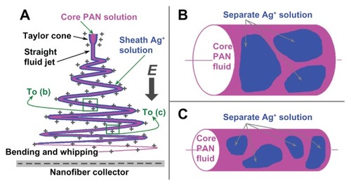
During the modified process, the electrospinnable core fluid jets had sufficient viscoelastic forces to balance Coulomb forces so allowing an even and continuous drawing. However, the sheath Ag+ solution should break up into separate segments along the core PAN fluid jets due to lack of viscoelasticity at a certain place in the bending and whipping region as determined by the sheath rate ratio. When a relatively small sheath flow rate was taken, such as the case of nanofibers F3 in , the separation of sheath solutions on the surface of core fluid would be a little easier when the fluid jet still has a bigger size, which in turn formed larger and fewer AgNPs when they were reduced using ultraviolet light. When a relatively big sheath flow rate was used, such as the case of nanofibers F4 in , the surrounding Ag+ solutions remained with the core PAN fluid for a longer time to enter the late period of the bending and whipping when the fluid jets had a smaller diameter. Thus correspondingly the sheath solutions were divided into smaller segments on the core PAN fluid jets, which in turn formed smaller and more AgNPs when they were reduced.
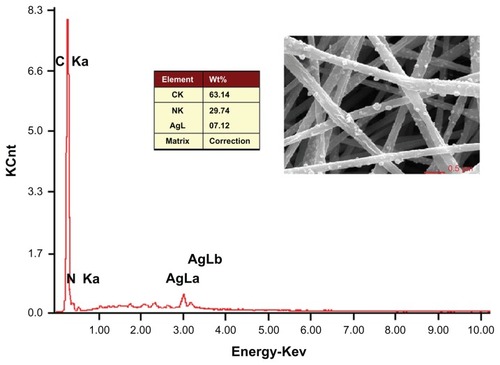
The EDS of the nanofibers F4 indicate the presence of Ag on the surface of the fibers (). The content of AgNPs in the PAN nanofibers was 7.12% by weight. The theoretical content of Ag in the nanofibers can be calculated from the electrospinning conditions: ie, (0.2 × 10%) × (108/170)/ [(0.2 × 10%) × (108/170) + 1 × 15%] = 7.81 %. The EDS result demonstrates that nearly all the AgNPs were successfully immobilized on the surface of PAN nanofibers F4.
Figure 5 EDS spectrum of the Ag-containing electrospun PAN nanofibers F4.
Abbreviations: EDS, energy-dispersive spectrometer; PAN, polyacrylonitrile.
Antibacterial activity
The antibacterial capacities of AgNPs-coated PAN nanofibers F3 and F4 against Gram-positive Wb800 and Gram-negative E. coli dh5α were explored by the viable cell counting method. Their abilities in inhibiting the growth of the test bacteria are shown in . The ABE of the nanofibers F4 against Wb800 and E. coli dh5α were over 99.9%. The ABE of the nanofibers F3 against Wb800 were also over 99.9%, and that against E. coli dh5α was about 99.8%. Pure PAN nanofibers F2 did not show any antibacterial properties. The AgNPs distributed on the surface of PAN nanofibers F3 and F4 were responsible for the strong antibacterial activity of the nanofibers.
Table 2 The antibacterial effect of AgNPs-coated PAN nanofiber against Wb800 and Escherichia coli dh5α (n = 6)
Previous electrospun polymer nanofibers have been employed as AgNPs-loaded matrices for the development antimicrobial materials. However, most of the functional Ag was buried in the inner part of the nanofibers and often a high content of Ag (up to 30%) was used in the formulation when single fluid electrospinning was exploited.Citation46 In contrast, the present study showed excellent antibacterial efficacies with only a content of less than 4% (w/w) Ag in the nanofibers (nanofibers F3) generated using a modified coaxial process. The position of AgNPs on the PAN nanofiber surface could endow the PAN nanofibers with excellent antibacterial capacities, and avoid wasting the noble metal buried in the inner part of the nanofibers by traditional electrospinning processes.
Conclusion
A modified coaxial electrospinning process was developed successfully to prepare a new type of antibacterial nanofiber in which AgNPs were distributed only on the surface of nanofibers to improve their antibacterial capability.
The nanofibers were prepared using a modified coaxial process and resulted in nanofibers that exhibited better quality than those obtained from the single fluid electrospinning in terms of nanofiber diameter, diameter distribution, and surface morphology. Under a sheath-to-core flow rate ratio of 0.2, the resultant PAN nanofibers have a diameter of 230 ± 70 nm with the AgNPs uniformly distributed on their surface. The antibacterial experiments demonstrated that both nanofibers F3 and F4 exhibited strong antimicrobial activities against B. subtilis Wb800 and E. coli dh5α even with a low Ag content present. Our study provides an example of the systematic design, preparation, and application of a novel type of structural antibacterial materials coated with AgNPs via a modified coaxial electrospinning.
Acknowledgments
This work was supported by the Key project of Shanghai Municipal Education Commission (No 13ZZ113) and National Science Foundation of China (Nos 31170920, 51173107, and 21101107).
Disclosure
The authors report no conflicts of interest in this work.
References
- WebsterTJNanomedicine: what’s in a definition?Int J Nanomedicine2006111511617722527
- SeilJTWebsterTJSpray deposition of live cells throughout the electrospinning process produces nanofibrous three-dimensional tissue scaffoldsInt J Nanomedicine201161095109921698076
- JannesariMVarshosazJMorshedMZamaniMComposite poly(vinyl alcohol)/poly(vinyl acetate) electrospun nanofibrous mats as a novel wound dressing matrix for controlled release of drugsInt J Nanomedicine20116993100321720511
- NevesNMCamposRPedroACunhaJMacedoFReisRLPatterning of polymer nanofiber meshes by electrospinning for biomedical applicationsInt J Nanomedicine2007243344818019842
- WangYZhangCZhangQLiPComposite electrospun nanomembranes of fish scale collagen peptides/chito-oligosaccharides: antibacterial properties and potential for wound dressingInt J Nanomedicine2011666767621556341
- TeoWERamakrishnaSA review on electrospinning design and nanofiber assembliesNanotechnology20061789106
- ZhaoYCaoXJiangLBio-mimic multichannel microtubes by a facile methodJ Am Chem Soc20072976476517243804
- YuJHFridrikhSVRutledgeGCProduction of submicrometer diameter fibers by two-fluid electrospinningAdv Mater20041615621566
- LiuZSunDDGuoPLeckieJOAn efficient bicomponent TiO2/SnO2 nanofiber photocatalyst fabricated by electrospinning with a side-by-side dual spinneret methodNano Lett200771081108517425281
- YarinALZussmanEWendorffJHGreinerAMaterial encapsulation and transport in core-shell micro/nanofibers, polymer and carbon nanotubes and micro/nanochannelsJ Mater Chem20071725852599
- DzenisYSpinning continuous fibers for nanotechnologyScience20043041917191915218134
- LocertalesIGBarreroAGuerreroICortijoRMarquezMGanan-CalvoAMMicro/nano encapsulation via electrified coaxial liquid jetsScience20022951695169811872835
- XinYHuangZLiWJiangZTongYWangCCore-sheath functional polymer nanofibers prepared by co-electrospinningEur Polym J20084410401045
- ZhangJFYangDZXuFZhangZPYinRXNieJElectrospun core-shell structure nanofibers from homogeneous solution of poly(ethyleneoxide)/chitosanMacromolecules20094252785284
- ParkCHLeeJOne-step immobilization of protein-encapsulated core/shell particles onto nanofibersMacromol Mater Eng2010295544550
- SillTJVon RecumHAElectrospinning: applications in drug delivery and tissue engineeringBiomaterials2008291989200618281090
- MogheKGuptaBSCo-axial electrospinning for nanofiber structures: preparation and applicationsPolym Rev200848353377
- DrorYSalalhaWAvrahamiROne-step production of polymeric microtubes by co-electrospinningSmall200731064107317315262
- YuDGBranford-WhiteCChattertonNPElectrospinning of concentrated polymer solutionsMacromolecules2010431074310746
- YuDGBranford-WhiteCBlighSWAWhiteKChattertonNPZhuLMImproving polymer nanofiber quality using a modified coaxial electrospinning processMacromol Rapid Commun20113274475021438063
- YuDGZhuLMBranford-WhiteCBlighSWAWhiteKCoaxial electrospinning with organic solvent for controlling the self-assembled nanoparticle sizeChem Commun20114712161218
- YuDGBranford-WhiteCWhiteKA modified coaxial electrospinning for preparing fibers from a high concentration polymer solutioneXPRESS Polym Lett20115732741
- YuDGLuPBranford-WhiteCYangJHWangXPolyacrylonitrile nanofibers prepared using co-axial electrospinning with LiCl solution as sheath fluidNanotechnology20112243530121955591
- YuDGWhiteKYangJHWangXQianWLiYPVP nanofibers prepared using co-axial electrospinning with salt solution as sheath fluidMater Lett2012677880
- YuDGYangJMLiLLuPZhuLMObtaining finer polymer nanofibers using two different electrospinning processesFiber Polym201213450455
- YuDGWilliamsGRGaoLDAnnie BlighSWYangJHWangXCoaxial electrospinning with sodium dodecylbenzene sulfonate solution for high quality polyacrylonitrile nanofibersColloid Surf A2012396161168
- YangJMYuDGCo-axial electrospinning with sodium thiocyanate solution for preparing polyacrylonitrile nanofibersJ Polym Res2012199789
- YuDGChattertonNPYangJHWangXLiaoYZCoaxial electrospinning with Triton X-100 solutions as sheath fluids for preparing PAN nanofibersMacromol Mater Eng2012297395401
- YuDGYuJHChenLWilliamsGRWangXModified coaxial electrospinning for the preparation of high-quality ketoprofen-loaded cellulose acetate nanofibersCarbohydr Polym2102901016102322840034
- EidKAMAzzazyHMEControlled synthesis and characterization of hollow flower-like silver nanostructuresInt J Nanomedicine201271543155022619511
- AllahverdiyevAMAbamorESBagirovaMAntileishmanial effect of silver nanoparticles and their enhanced antiparasitic activity under ultraviolet lightInt J Nanomedicine201162705271422114501
- ChenMYangZWuHPanXXieXWuCAntimicrobial activity and the mechanism of silver nanoparticle thermosensitive gelInt J Nanomedicine201162873287722131833
- JangSParkJWCha1HRSilver nanoparticles modify VEGF signaling pathway and mucus hypersecretion in allergic airway inflammationInt J Nanomedicine201271329134322457593
- SinghSKGoswamiKSharmaRDReddyMVRDashDNovel microfilaricidal activity of nanosilverInt J Nanomedicine201271023103022393295
- BeiYChenXLiuYNovel norcantharidin-loaded liver targeting chitosan nanoparticles to enhance intestinal absorptionInt J Nanomedicine201271819182722619530
- SuYHYinZFXinHLOptimized antimicrobial and antiproliferative activities of titanate nanofibers containing silverInt J Nanomedicine201161579158621845048
- SeilJTWebsterTJAntimicrobial applications of nanotechnology: methods and literatureInt J Nanomedicine201272767278122745541
- HuGXiaoLTongPAntibacterial homeostatic dressings with nanoporous bioglass containing silverInt J Nanomedicine201272613262022745538
- ElzatahryAAAl-EniziAMElsayedEANanofiber composites containing N-heterocyclic carbine complexes with antimicrobial activityInt J Nanomedicine201272829283222745545
- JenaPMohantySMallickRJacobBSonawaneAToxicity and antibacterial assessment of chitosan coated silver nanoparticles on human pathogens and macrophage cellsInt J Nanomedicine201271805181822619529
- ChiaoSHLinSHShenCIEfficacy and safety of nanohybrids comprising silver nanoparticles and silicate clay for controlling Salmonella infectionInt J Nanomedicine201272421243222654516
- SharmaVKYngardRALinYSilver nanoparticles: Green synthesis and their antimicrobial activitiesAdv Colloid Interfac Sci20091458396
- LimSKLeeSKHwangSHKimHPhotocatalytic deposition of silver nanoparticles organic/inorganic composite nanofibersMacromol Mater Eng200629112651270
- SonWKYoukJHLeeTSParkWHPreparation of Antimicrobial ultrafine cellulose acetate fibers with silver nanoparticlesMacromol Rapid Commun20042516321637
- ChouWLYuDGYangMCThe preparation and characterization of silver-loading cellulose acetate hollow fiber membrane for water treatmentPolym Adv Technol200516600607
- XuXYangQWangYYuHChenXJingXBiodegradable electrospun poly(L-lactide) fibers containing antibacterial silver nanoparticlesEuro Polym J20064220812087
- HongKHPreparation and properties of electrospun poly (vinyl alcohol)/silver fiber web as wound dressingsPolym Eng Sci2007474349
- CarlbergBYeLLLiuJSurface-confined synthesis of silver nanoparticle composite coating on electrospun polyimide nanofibersSmall201173057306621901829
- YuLNZhaoJShenLDGaoYWangXFAg-coated PAN nanofibers prepared by poly(dopamine)-assisted electroless platingAdv Mater Res2012482–48425432546
- ZhaoPFanJSilver polyhedron coated electrospun nylon 6 nano-fibrous membrane with good infrared extinction, ultraviolet shielding and water vapor permeabilityJ Appl Polym Sci201212451385144
- WikipediaPolyacrylonitrile Available from: http://en.wikipedia.org/wiki/PolyacrylonitrileAccessed on September 10, 2012
- MelaiyeASunZHindiKSilver(I)-imidazole cyclophane gemdiol complexes encapsulated by electrospun tecophilic nanofibers: Formation of nanosilver particles and antimicrobial activityJ Am Chem Soc20051272285229115713108
- SonWKYoukJHLeeTSParkWHPreparation of antimicrobial ultrafine cellulose acetate fibers with silver nanoparticlesMacromol Rapid Commun20042516321637
- YeoLYFriendJRElectrospinning carbon nanotube polymer composite nanofibersJ Exp Nanosci20062177209