 ?Mathematical formulae have been encoded as MathML and are displayed in this HTML version using MathJax in order to improve their display. Uncheck the box to turn MathJax off. This feature requires Javascript. Click on a formula to zoom.
Abstract
The aim of this study was to fabricate fibrinogen (Fbg) microfibers with different structural characteristics for the development of 3-D tissue-engineering scaffolds. Fabricated Fbg microfibers were investigated for their biomolecule encapsulation, cell adhesion, and proliferations. Microfibers with three different concentrations of Fbg (5, 10, and 15 wt%) were prepared by a gel solvent-extraction method using a silicone rubber tube. Fbg microfibers were covalently modified with fibronectin (FN) by using water-soluble 1-ethyl-3-(3-dimethylaminopropyl) carbodiimide as the cross-linking agent. Fbg microfibers were characterized by their FN cross-linking properties, structural morphology, and in vitro degradation. Furthermore, FN/Fbg microfibers were evaluated for cell attachment and proliferation. The bio-compatibility and cell proliferation of the microfibers were assessed by measuring adenosine triphosphate activity in C2C12 fibroblast cells. Cell attachment and proliferation on microfibers were further examined using fluorescence and scanning electron microscopic images. FN loading on the microfibers was confirmed by fluorescence and infrared spectroscopy. Surface morphology was characterized by scanning electron microscopy, and showed highly aligned nanostructures for fibers made with 15 wt% Fbg, a more porous structure for fibers made with 10 wt% Fbg, and a less porous structure for those made with 5 wt% Fbg. Controlled biodegradation of the fiber was observed for 8 weeks by using an in vitro proteolytic degradation assay. Fbg microfibers with highly aligned nanostructures (15 wt%) showed enhanced biomolecule encapsulation, as well as higher cell adhesion and proliferation than another two types of FN/Fbg fibers (5 and 10 wt%) and unmodified Fbg fibers. The promising results obtained from the present study reveal that optimal structure of Fbg microfibers could be used as a potential substratum for growth factors or drug release, especially in wound healing and vascular tissue engineering, in which fibers could be applied to promote and orient cell adhesion and proliferation.
Introduction
The goal of tissue engineering is to develop functional substitutes for tissues and organs that may offer a permanent result to damaged tissues or organs without relying on additional therapies. In tissue engineering, protein-based polymer scaffolds have been used to precisely direct biomolecule adsorption, sustained release, and biochemical interactions with a variety of cells, which ultimately improves cell proliferation as well as tissue and organ growth or regeneration in the host.Citation1,Citation2 Additionally, these scaffolds may facilitate cell adhesion, extracellular matrix (ECM) production, morphogenesis, and differentiation by mimicking in vivo microenvironments, by offering physical and chemical cues in regulating cellular functions. Tissue-engineered scaffolds have been fabricated from several synthetic polymers,Citation3,Citation4 as well as naturally occurring biomaterials, such as collagen, gelatin, fibrinogen (Fbg), hyaluronic acid, and silk.Citation5,Citation6 Among these natural biomaterials, Fbg has many advantages because of its excellent biochemical interactions and superior physiological activities, such as selective cell adhesion, mechanical properties similar to natural tissues (eg, blood vessels and animal heart vessels), and enzymatic biodegradability (eg, gelatin and collagen).Citation7 Fbg is often considered to be nature’s provisional ECM because of its importance in the early stages of hemostasis and wound repair in addition to its role in clotting.Citation8 Furthermore, Fbg contains two arginine-glycine-aspartic acid (RGD) integrin-binding sites in the Aα chain, which usually bind endothelial and fibroblast cells. Fbg has been shown to bind fibroblast growth factor, vascular endothelial growth factor, insulin-like growth factor, and the Aα chain of fibronectin with high affinity.Citation9,Citation10 Fbg-based scaffolds such as nanofibers, hydrogels, and microbeads have been widely investigated for vascular, skin, and bone tissue engineering because of their respective cell adhesion, proliferation, and protein synthesis characteristics.Citation11–Citation13 The abundance of available ɛ-amino groups of lysine on the Fbg surface preferentially induces peptide-bond formation between Fbg and external biomolecules with the appropriate functional groups.
Generally, 3-D scaffolds can render a better association between single cells and organs over conventional 2-D cultures, as the third dimension in the 3-D scaffold offers an additional platform for cell–cell interactions, cell migration, and cell morphogenesis, which are all important in regulating the cell cycle and tissue functions.Citation14,Citation15 3-D fiber matrices are a particularly favorable replacement for natural scaffolds due to their porous morphology, isotropic structures, and uniform structure. In addition, 3-D porous constructs allow for the transport of nutrients and waste metabolites during tissue or organ development. The 3-D fiber scaffolds in the micron-size range have higher mechanical strength than their counterparts, which could enhance cell adhesion, proliferation, and ease of handling during in vitro postmodifications or implantation,Citation16 although they generally lack the topographical features needed to resemble native ECM (due to the lack of nanostructures). On the other hand, 3-D scaffolds fabricated on the nanoscale exhibit more success in directing cells towards certain cellular morphologies, differentiation, and many other important cellular functions, but usually at the cost of reduced mechanical strength.Citation17 Therefore, in order to establish in vivo microenvironments, the next generation of 3-D tissue-engineering scaffolds should integrate both microstructures and nanoscale architectures, which could enhance both mechanical strength and cellular functions. However, there are some difficulties in fabricating thick 3-D microstructures, scaffolds with a nanoscale integration or morphology due to the characteristics of polymers. In addition, the introduction of nanostructures to microfiber scaffolds is generally not suitable for protein-based natural polymers. For example, chemical etching methods can create nanostructures or nanotopographies on the surface of 3-D microfiber scaffolds by soaking the microfibers in etchants (organic solvent), such as hydrofluoric acid and NaOH,Citation18 which could damage and degrade the polymer scaffolds.Citation19–Citation21 Also, electrospinning may not be suitable for aqueous soluble natural polymers (due to limitations in spinning these into fibers). Further difficulties include the observation of degradation when natural polymers are dissolved in organic solvent, the production of aligned fibers is difficult, and fibers that are too thin having low mechanical strength.Citation22,Citation23 Melt spinning requires bulky instruments for its high-temperature process, and high temperatures denature and limit protein loading. The microfluidic method is cost-effective, but it is more appropriate for select synthetic polymers such as poly(lactic-co-glycolic acid), di- or triblock copolymers, and other synthetic polymers that are freely soluble in organic solvents.Citation16,Citation24
Furthermore, to improve or establish cellular function, cell behavior, and cell responses on polymer surfaces, biomolecule grafting is necessary, for which different approaches have been introduced. Physical adsorption, physical entrapment, and cross-linking are commonly used to immobilize biomolecules on polymer surfaces. The covalent cross-linking of biomolecules on polymer surfaces is a more complex process, but it overcomes drawbacks, such as the loss of bioactivity from aggregation, conformational changes, and denaturation related to physical adsorption and entrapment methods.Citation25,Citation26 However, covalent cross-linking of biomolecules is dependent on the presence of appropriate functional moieties on both the polymeric material and the target molecule.
Fibronectin (FN) is one of the largest protein components of the ECM, and it has been frequently studied because it is involved in many significant physiological processes, such as cell adhesion, migration, differentiation, survival, and wound healing. FN contains an RGD-binding site, which commonly binds endothelial and fibroblast cells.Citation27 Since FN is an important cellular adhesion protein, it can be used to regulate several aspects of cellular association with the ECM through a variety of integrin–ligand interactions. Integrin forms a bridge between the adhesion protein and the cytoskeleton, which supports cell adhesion to the biomaterial.Citation28 Various studies have investigated adhesive proteins on polymer carriers to regulate cellular activities.Citation29 A recent study revealed that natural and synthetic polymer surfaces that had been modified with FN could improve cell adhesion and accelerate cell proliferation.Citation30
In this study, we describe the fabrication process for Fbg microfiber scaffolds by using a simple and cost-effective micron-sized silicone tube. Furthermore, to investigate cell adhesion, proliferation, and biomolecule grafting on Fbg fibers, we also fabricated different structural characteristic Fbg microfibers by varying polymer concentrations. Fbg microfibers were then covalently grafted with FN, with 1-ethyl-3-(3-dimethylaminopropyl) carbodiimide hydrochloride (EDC) as a binder. The FN/Fbg microfiber surfaces were characterized under scanning electron microscopy (SEM), and FN immobilization efficacy and fibrinolytic degradation were analyzed. Finally, a mouse muscle-fibroblast cell line was used to evaluate cell viability, cytocompatibility, and bioactivity of the microfiber matrix.
Materials and methods
Materials
Bovine fibrinogen (molecular weight 340 kDa), fibronectin from bovine plasma, EDC, N-hydroxysuccinimide (NHS), osmium tetroxide 4 wt% solution in water, and hexamethyldisilazane (HMDS) were purchased from Fluka. Dulbecco’s modified Eagle medium, fetal bovine serum (FBS), and penicillin-streptomycin were purchased from Life Technologies (Carlsbad, CA, USA). For immunofluorescence, 4′,6-diamidine-2-phenylindole dihydrochloride (DAPI) and Alexa Fluor 488 were purchased from Life Technologies. The cell-proliferation kit CellTiter-Glo was purchased from Promega (Fitchburg, WI, USA). Lys-plasminogen and tissue Plasminogen Activator (t-PA) were purchased from HTI (Boston, MA, USA). C2C12 mouse muscle fibroblasts were provided freely by NanoEntek (Seoul, South Korea). All other chemicals used in this work were of analytical grade.
Fiber-fabrication process
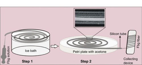
Fbg microfibers were fabricated by the gel solvent-extraction method by using silicone rubber tubes, as reported recently,Citation31 with some modifications. Briefly, three different concentrations (5%, 10%, and 15% w/v) of Fbg solutions were prepared with phosphate-buffered saline, and the solution was then filtered through a 0.45 μm syringe filter. The fabrication of microfibers mainly consisted of two steps. In step one, the Fbg solution was injected from one end of the coil-shaped silicone tube (0.76 mm ID) to the other, and was then cooled to 0°C–4°C in an ice bath without shaking. In step two, the gel tube was completely immersed in acetone (previously cooled to 4°C) at room temperature. Once the complete solvent extraction was finished, the flexible white solid fiber was rolled out from the tube. Finally, the rolled fiber was vacuum-dried for 2 days. A schematic representation of the complete fiber formation is shown in .
Figure 1 Schematic diagram of the fabrication process for fibrinogen (Fbg) microfibers (inlet: optical micrograph showing fiber formation inside the silicone tube during solvent extraction).
Covalent cross-linking of FN or FN immobilization
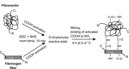
The method used for FN immobilization was based on previous studies of the immobilization of peptides or protein on amino-phase substrates.Citation32,Citation33 Briefly, with some modification, Fbg microfibers were covalently cross-linked with FN, using EDC as a cross-linking agent. The cross-linking reaction consisted of two steps. In step one, the prepared Fbg microfibers (250 mg in acetone) and 30 μL of FN (2 mg/mL) were separately added to EDC (3 mM) and NHS (2 mM) in two different tubes, and gentle rotation was continued for 10 minutes at room temperature in order to preactivate the carboxyl groups available on Fbg and FN. In step two, both tubes were mixed together, and the final volume was made up to 10 mL with an acetone:water mixture (4:1). The rotation was continued for 6 hours at 0°C–4°C using a gentle rotator (Intelli Mixture, Seoul, South Korea) at a speed of 30 rpm, as shown in . Finally, the FN-grafted Fbg fibers were washed with distilled water, followed by moisture removal with 50% and 100% acetone, and were then vacuum-dried for 1 day prior to further characterization.
Figure 2 Schematic illustration of conjugating fibronectin and fibrinogen by 1-ethyl-3-(3-dimethylaminopropyl) carbodiimide hydrochloride (EDC)/N-hydroxysuccinimide (NHS).
Fluorescence microscopy
To confirm FN immobilization, we used Alexa Fluor 488 fluorescently labeled goat anti-mouse IgG antibody. The immobilization of FN on Fbg microfibers was observed with a fluorescence microscope (Eclipse TE2000-U; Nikon, Tokyo, Japan).
FT-IR characterization study
For further confirmation of FN grafting with Fbg fibers, Fourier-transform infrared spectrophotometry (FT-IR) (Tensor 27; Bruker, Billerica, MA, USA) was carried out on the FN-Fbg fibers.
Quantification of FN encapsulation efficacy
FN immobilization efficacy on the Fbg microfiber surface was determined using the Custódio method.Citation33 After 6 hours of FN cross-linking, the solution was measured by a colorimetric method to quantify un-cross-linked FN using the Bradford protein assay. The measured value was subtracted from the initial measurement, which corresponded to the FN cross-linked on the Fbg fiber surface. In the Bradford assay, an equal amount of Bradford reagent and sample solution were mixed in a 96-well plate and were incubated at 37°C for 10 minutes in a dark room; the absorbance was then measured at 568 nm using a PerkinElmer (Waltham, MA, USA) Victor3.
Fiber morphological characterization
The morphology of Fbg microfibers was analyzed by both optical microscopy and SEM (S-4700 type II; Hitachi, Tokyo, Japan). The optical light microscopic images were taken to observe the bulk morphology of the three Fbg microfibers with different diameters (light microscope, NIS-Elements software; Nikon). Next, SEM images were analyzed to examine outer morphology and ultrafine structures of the microfibers. To obtain SEM images, the microfiber was attached over the adhesive carbon tape and was sputter-coated with gold for 90 seconds at 10 mA, and images were obtained at 15 kV.
In vitro degradation through fibrinolysis
For testing the in vitro degradation of Fbg fibers, fibrinolytic degradation was monitored after the addition of the proteolytic medium. Fbg fibers (300 mg) were cut into a smaller size (less than 1 cm in length) and were placed in 1.5 mL Eppendorf (Hamburg, Germany) tubes containing proteolytic medium (Tris-buffered saline [TBS, 25 μL], CaCl2 [10 μL of 50 mM], t-PA [20 μL of 20 μg/mL], lys-plasminogen [2.5 μL of 1 mM], and additional TBS [42.5 μL]). Then, the tube was incubated at 37°C with mild rotation (20 rpm) for 8 weeks. At different time intervals, triplicate samples were rinsed with double-distilled water and were vacuum-dried at room temperature until a constant weight was reached. Every 7 days, the degradation medium was replaced with freshly prepared proteolytic medium. The weight loss was calculated as follows:
W0 and W1 are the weights of the sample before and after fibrinolytic degradation, respectively. The reported weight loss is the average of three samples.
Cell-viability study
Cell viability and proliferation were assessed using the CellTiter-Glo luminescent cell viability assay kit, in which the luciferase-catalyzed luciferin/adenosine triphosphate (ATP) reaction provides an indicator of cell number.Citation34 For these studies, both unmodified and FN-modified fibers (5 mg) were sterilized under ultraviolet light for 30 minutes and were prewetted with modified Eagle medium for 1 hour prior to seeding the cells. Fibroblast cells were seeded into 96-well opaque plates (4 × 10Citation4 cells/well) with 100 μL of culture medium containing 10% FBS, penicillin (100 U/mL), and streptomycin sulfate (100 mg/mL), and were then incubated overnight under normal growth conditions to attach the cells. The medium was then replaced with the same volume of culture medium containing 1% FBS, with 5 mg of each of the different-sized fibers, after which the incubation continued for 5 days. At 1, 3, and 5 days, cell proliferation was analyzed by measuring ATP luminescence. To obtain a value for background luminescence, the control was maintained in the same conditions as above, but in the absence of cells. After 3 days, the attachment of metabolically active fibroblast cells on FN/Fbg microfibers was examined by fluorescence microscopy using DAPI nuclear staining. After treating the cells with microfibers for a specific period the culture medium was removed and the cells were washed once with a DAPI-methanol solution (1 μg/mL). Then, the plate was incubated with 1 mL of DAPI-methanol solution for 15 minutes at 37°C. The staining solution was removed the cells were washed once with methanol, and the cell-attached microfibers were observed by fluorescence microscopy (Eclipse TE 2000-U).
Cell-adhesion study and cell morphology
After treating the fiber matrix with fibroblast cells, the matrix was gently rinsed twice with sodium phosphate buffer (pH 7.4) to eliminate nonadherent cells, and was then fixed with 2.5% glutaraldehyde in phosphate-buffered saline for 30 minutes at room temperature. The matrix was postfixed in 0.5 mL of 0.5% osmium tetroxide in sodium phosphate buffer for 1 hour at room temperature. The fixation solution was then removed and the samples were dehydrated by immersing in 100% HMDS for 3 minutes. HMDS has a low surface tension and helps preserve surface structure by cross-linking proteins.Citation35 The samples were dried in a desiccator for 30 minutes, sputter-coated and examined under SEM.
Statistical analysis
The effect of the covalent grafting approach of FN on the Fbg fibers and the cell response in terms of attachment and proliferation to the different-sized fibers were evaluated and the results are represented as mean values ± standard deviation (n = 3). Groups were compared using an independent paired t-test, with P < 0.05 and P < 0.01 indicating statistical significance.
Results and discussion
Fiber fabrication and morphological characterization
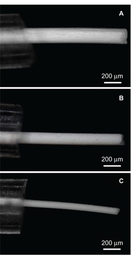
Fbg microfibers with various diameter sizes and different structural characteristics were successfully fabricated using three concentrations (5, 10, and 15 wt%) of Fbg solutions by a gel solvent-extraction method with a micron-sized silicone tube. shows the optical microscopic images of the microfibers when they were removed from the silicone tube, which clearly shows Fbg fibers with three different diameters. Decreased fiber size and increased gelation time were observed with decreasing Fbg concentrations. In the Fbg microfiber-fabrication process, the silicone tube inner diameter, polymer concentration, and gelation time played the most important roles. For example, an Fbg solution of 15 wt% became completely gelatinous within 20–30 minutes, while the solution of 10 wt% Fbg took 30–40 minutes, and the lowest concentration of Fbg solution (5 wt%) took more than 40 minutes for complete gelation. In the same way, for the solvent-extraction process, the 15 wt% and 10 wt% Fbg-gel took, respectively, 8–10 and 15–20 minutes, and the lowest concentration, 5 wt%, took more than 30 minutes. If the polymer particles were not completely solidified during gelation, they were removed as debris or as particles from the silicone tube during the solvent-extraction process. In our previous work, after gelation, only the injected end was connected with the precooled acetone reservoir. Here, the coil-shaped silicone tube was completely immersed in a petri plate containing precooled acetone, which reduced the extraction time by comparison, since the extraction occurred from both sides of the silicone tube ().
Figure 3 Light microscopic images clearly showed the three different diameters of the fibrinogen (Fbg) microfibers, as being pulled from the silicone tube. (A) 15 wt% Fbg fiber; (B) 10 wt% Fbg fiber; (C) 5 wt% Fbg fiber.
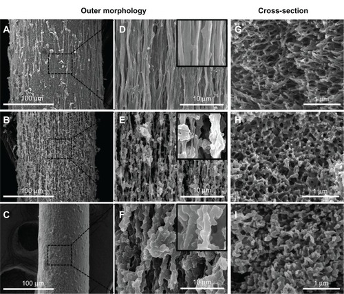
Furthermore, changing the Fbg concentration had a significant impact on the microfiber structure; 15, 10, and 5 wt% Fbg concentrations resulted in an aligned nanostructure, highly porous aligned fibers, and less porous unaligned microfibers, respectively. The characteristic fiber-structure formation was based on the diffusion-induced phase separation, namely precipitation by solvent extraction and immersion precipitation. When there was no chemical reaction between the polymer solution and the organic solvent, diffusional mass exchange occurred, which resulted in changes in the local composition of the polymer particles and demixing, thereby resulting in different morphological fiber structures. Therefore, microfibers fabricated from a high concentration (15 wt%) of Fbg had highly aligned nanostructures because they contained a relatively high content of polymer particles; fibers made from the middle concentration of Fbg (10 wt%) had highly porous fibers, due to a greater volume of solvent extraction; and fibers formed from the lowest concentration of Fbg (5 wt%) were less porous with an unaligned structure (). Based on the above theory, microfibers made from 5 wt% Fbg might be expected to be more porous than those made from 10 wt% Fbg because of greater solvent extraction. However, this result was not observed because they contained fewer polymer particles, and so could not form either a highly porous or aligned fiber structure. In addition, as the polymer concentration decreased, the solvent-extraction time increased because of the need for a greater number of aqueous extractions. This led to a slowing of the movement of the organic solvent, resulting in less organized fibers with a less porous structure. Hence, both polymer concentration and gelation time played an important role in the overall size and structural characteristics of the microfibers. This simple and economical method for the fabrication of tissue-engineering scaffolds offers a number of advantages, such as Fbg scaffolds, varying diameter, and diverse structural characteristics. Furthermore, a variety of biomedical and/or pharmaceutical applications would favor a fiber scaffold with aligned nanostructuresCitation36 and porous structures.Citation37 Microfibers containing aligned nanostructures and porous structures could be more beneficial for the sustained release of active biomolecules as well as for providing orientation of cell growth towards specific cell or tissue regeneration. Moreover, these microfibers could enhance the surface area for biomolecule immobilization, provide an anchoring point for cell accommodation, and maintain controlled bioavailability, as the porous structures can help to transport nutrients and waste metabolites in tissue regeneration. Many research laboratories have focused on fabricating polymer microfibers (synthetic and natural) with various characteristics toward the development of 3-D tissue-engineering scaffolds. The simple gel solvent-extraction method can be used for fabricating other synthetic and natural polymer fibers, when the polymers form a gel in aqueous or organic solvents.
Figure 4 Scanning electron microscopy images of fibrinogen (Fbg) microfibers fabricated from three different concentrations of Fbg. Decreasing fiber diameter was observed with decreasing Fbg concentration; images (A–C) show 200 μm, 150 μm, and 75 μm fibers, respectively, which were made from 15, 10, and 5 wt% Fbg, respectively. Images (D–F) represent highly aligned nanostructures, highly interporous fibers with aggregated structures, and less porous fibers with unaligned structure, respectively, and are the same as the lower magnification images in (A–C), respectively (inlet images scale bar is 1 μm). The cross-sectioned scanning electron microscopy image confirmed a higher degree of nanofiber alignment from microfibers made from 15 wt% Fbg (G), highly porous structure fibers made from 10 wt% Fbg (H), and a less porous fiber structure made from 5 wt% Fbg (I).
FN immobilization on Fbg fibers
In this study, FN was covalently immobilized on Fbg microfibers by forming peptide bonds between both the polymer carrier and target molecule. EDC and NHS were used to preactivate the carboxyl groups from FN and Fbg. The amount of immobilized FN was quantitatively assessed through an indirect protein assay (Bradford method), and the results are shown in . The quantitative results revealed that FN was successfully cross-linked with Fbg fibers, and demonstrated that FN-immobilization efficiency increased with increasing fiber-diameter size or increasing number of nanostructures. The amounts of FN immobilization by covalent cross-linking for 15, 10, and 5 wt% Fbg fibers were 17.4, 13.5, and 9.8 μg/mg, respectively. The fiber made from 15 wt% Fbg showed higher amounts of FN grafting because of a high surface-to-volume ratio of the scaffolds. Since the microfibers were composed of many nanostructured fibers, the abundant number of arginine and lysine residues on the Fbg surface could freely be used for peptide-bond formation with FN. FN-immobilization efficiency was reduced for fibers made with 10 and 5 wt% Fbg. In theory, the smaller microfibers made with 5 wt Fbg could have been immobilized with more FN than the fibers with a larger diameter (ie, those made from 10 or 15 wt% Fbg). However, since these smaller microfibers contained fewer nanostructures, the overall surface area was reduced, with less exposed arginine and lysine residues available to make peptide bonds.
Figure 5 (A) Quantity of fibronectin (FN) covalently immobilized on three different structures of fibrinogen (Fbg) fibers after a 6-hour cross-linking reaction (n = 3). (B) Fluorescent micrographs of FN-grafted Fbg microfibers (different magnifications).
Note: Images show the uniform grafting of adhesion protein on Fbg surfaces.
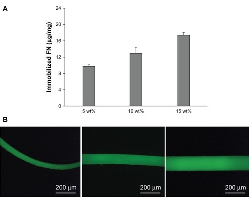
FN-immobilized fiber images, as seen under a confocal microscope, are shown in , and reveal that FN was uniformly incorporated on the Fbg fiber surface. Other types of biomolecules and cytokines that have an appropriate functional group could also be easily immobilized on the Fbg surface via intermolecular cross-linking, as other natural or synthetic biomaterials that are coated or functionalized could improve tissue regeneration. For cases where the target biomolecule or small peptide does not have suitable functional groups, the biomolecules can be premixed with the polymer solution before being injected into the silicone tube. Previous studies have confirmed that biomaterials functionalized with FN have improved cellular function, and that the polymerization of FN into natural polymers increased actin organization and regulated the composition of the natural polymers, thereby increasing the strength, toughness, and stability of the polymers.Citation38,Citation39 Recent studies have focused on understanding the biochemical communication of FN in the covalently cross-linked state and the in vitro cellular response.Citation33
FT-IR characterization study
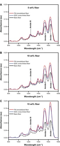
The FT-IR spectra of the three fibers (bare, EDC cross-linked, and FN/Fbg fibers) were characterized within a range of vibration frequencies from 800 to 1800 cm−1 to ensure the successful cross-linking between FN and the Fbg fibers, as proteins exhibit characteristic bands in this spectral range. Two dominant amide bonds were observed at 1649 cm−1 (amide I) due to −C═O stretching vibrations of large-class natural proteins, and at 1538 cm−1 (amide II) due to −C(O) stretching of aliphatic amides and the in-plane N−H bending mode. The amide III bond was assigned at 1245 cm−1 because of N−H bending and the complex vibration mode, as reported earlier for Fbg.Citation40,Citation41 The peaks centered at 1450 and 1393 cm−1 were due to −CH2 deformation and amino acid side-chain vibrations, respectively.
For the EDC-treated Fbg fibers, the amide I peak shifted from 1649 to 1637 cm−1, the amide II peak shifted from 1538 to 1524 cm−1, and the amide III band shifted from 1244 to 1234 cm−1. This shift can be attributed to the potential cross-linking between two oppositely charged molecules (−CO2− and −NH3+), leading to increased bond length and reduced stretching frequency, which ultimately resulted in a wavelength shift from the higher- to lower-frequency regions. Therefore, the reduced stretching frequency and peak shifts towards lower wavelengths were attributed to intramolecular Fbg cross-linking. Fbg fibers treated with FN and EDC, in addition to the peak shift, showed increased peak intensity over the EDC cross-linked Fbg fibers in all three amide bands (amide I, amide II, and amide III), suggesting that intermolecular cross-linking occurred between Fbg and FN. Furthermore, peak intensity increased with increasing Fbg concentration, indicating that FN immobilization was enhanced with increasing nanostructure-aligned Fbg fibers. For example, the 15 wt% Fbg fibers showed maximum peak intensity, indicating higher peptide-bond formation, between Fbg and FN, since the Fbg fiber could expose their free arginine and lysine residues due to the presence of more nanostructures. Reduced peak intensity was observed with 10 and 5 wt% Fbg fibers, indicating reduced peptide-bond formation for these fibers (). The increased peak intensity represented increased peptide-bond formation, as reported previously for another natural protein polymer.Citation42 These absorption peaks also confirmed that inter- and intramolecular cross-linking occurred to produce a cross-linked Fbg-FN network. Finally, the physical characterization revealed that additional peaks were not observed after cross-linking, indicating that there were no chemical interactions between Fbg and EDC or FN and EDC.
Figure 6 Fourier-transform infrared spectroscopy of fibrinogen (Fbg) microfibers as a function of fibronectin (FN) cross-linking. Images confirm FN immobilization on the Fbg fiber surfaces. The fibers treated with 1-ethyl-3-(3-dimethylaminopropyl) carbodiimide (EDC) only show the peak shifting towards a lower wavelength and higher peak intensity (blue line) compared to bare Fbg fibers (black line), due to the potential cross-linking within Fbg molecules. The FN cross-linked fibers in addition to EDC show a much higher peak intensity (red line) along with peak shifting, which confirms the cross-linking between FN and Fbg. The increase in peak intensity and peak shifting was due to an increasing number of peptide bonds. (A) 5 wt% Fbg fiber; (B) 10 wt% Fbg fibers; (C) 15 wt% Fbg fiber.
Fibrinolytic degradation
Degradation experiments were critically important for our study, because application of the scaffold is directly dependent on degradation time. Fbg can be easily regulated by plasmin or other proteolytic enzymes in vitro and in vivo.Citation43 Here, the Fbg fiber degradation was quantitatively evaluated by weight loss during the enzymatic degradation. FN grafted using the three Fbg microfibers was incubated with plasminogen and tPA for 8 weeks. Every 7 days, the degradation ratio was monitored by measuring fiber weight loss. After 4 weeks of degradation, the fiber matrix losses were approximately 23.4%, 31.2%, and 56.8% of their weight for each of the 15, 10, and 5 wt% fibers, respectively. The 5 and 10 wt% fibers were completely degraded after 7 and 9 weeks of incubation, respectively, while the microfiber made from 15 wt% Fbg remained relatively intact until 12 weeks. depicts the overall degradation ratio of the three fibers at different times in vitro. From the degradation studies, we determined that the microfiber degradation ratio completely depended upon the structural characteristics and number of peptide bonds. At the end of 7 weeks of degradation, the nanostructure-aligned Fbg microfibers (from 15 wt% Fbg) showed the lowest rate of degradation with a loss of 60.3%, due to an increased number of peptide bonds (ie, an increased surface-to-volume ratio and a greater number of exposed arginine and lysine residues).
Figure 7 Fibrinolytic degradation of fibrinogen (Fbg) microfibers made with three different diameter sizes shows the rate of degradation at different time intervals (n = 3).
Abbreviation: FN, fibronectin.
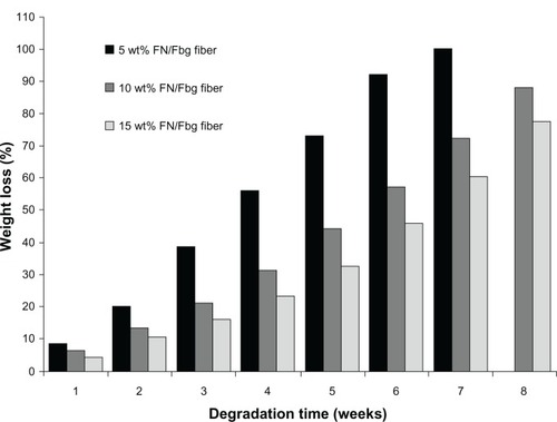
Since polymers that have free hydrogen molecules can more easily make hydrogen bonds in aqueous medium, swelling occurs via diffusion of aqueous medium followed by hydrolysis, which results in the cleavage of the polymer into small fragments by proteolytic enzymes.Citation43 Plasminogen could be activated by tPA to a serine protease, plasmin, which could degrade Fbg by cleaving arginine or lysine residues at their carboxyl terminal peptide bond. Therefore, plasmin would take a longer time to degrade 15 wt% Fbg microfibers than it would to degrade the 10 and 5 wt% fibers. Indeed, the quantitative weight-loss data indicated that the 5 and 10 wt% Fbg fibers were degraded faster than the microfibers produced from 15 wt% Fbg.
Cell-viability study
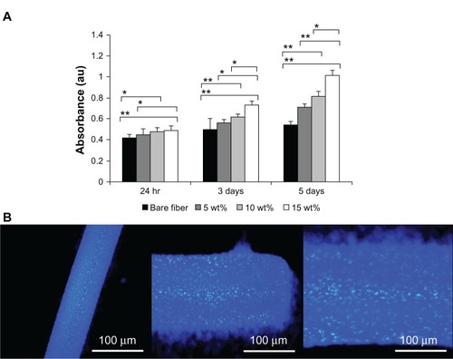
The bioactivity and cell proliferation of the Fbg and FN/Fbg microfibers were evaluated by measuring mitochondrial ATP activity using the CellTiter-Glo luminescent cell-viability assay. Bare Fbg and FN/Fbg microfibers were cultured with mouse fibroblast cells for 5 days. The cell-proliferation assay was performed at days 1, 3, and 5. Although both bare Fbg and all three different structures of FN/Fbg fibers surfaces exhibited nearly the same optical density values at the early stage (24 hours) of cell culture, in later stages (3 and 5 days), cells cultured on FN/Fbg microfibers exhibited a clear enhancement in ATP luminescence measurements when compared to that of bare Fbg fibers (). Furthermore, our results indicated that the optical density values increased with increasing fiber diameter due to enhanced cell proliferation, which is consistent with the FN immobilization data. These data indicate that increased cell proliferation with increasing FN grafting is consistent with the findings of a recently published work on natural carbohydrate polymers grafted with FN.Citation33 Although the assay results revealed that both Fbg and FN/Fbg were biocompatible, the microfibers containing nanostructures could enhance much higher cell proliferation compared to highly porous and less porous microfibers. It is well known that FN is a large ECM protein that has been extensively studied because of its significant role in numerous physiological processes, such as cell adhesion, migration, proliferation, survival, and wound healing.Citation44,Citation45 The availability of an FN–RGD binding site, in many cases, was sufficient to regulate cellular activities,Citation46,Citation47 and offered important secondary actions, which regulate cell binding, cell signaling, cell proliferation, and differentiation. These results demonstrate that bare Fbg microfibers differ significantly in cell proliferation compared with FN/Fbg microfibers, indicating that the bare Fbg microfibers are cytocompatible, but that proliferation was not improved, as observed for FN/Fbg fibers. Mouse fibroblast cells cultured on the FN/Fbg microfibers were stained with DAPI, which stains DNA (). Moreover, the cells were attached well to the microfiber surface, which clearly indicates that the FN/Fbg microfibers were compatible with cells andenhanced cell attachment and proliferation.
Figure 8 (A) CellTiter-Glo Luminescent Cell Viability assay results of cultured mouse muscle-fibroblast cells on fibrinogen microfiber scaffolds at different times. Groups were compared using an independent paired t-test. Error bars represent means ± standard deviation for n = 3. **P < 0.01; *P < 0.05. (B) DAPI (4′,6-diamidino-2-phenylindole) nuclear staining images reveal mouse muscle-fibroblast cell attachment on fibrinogen fibers (different magnifications).
Cell-attachment/morphology study
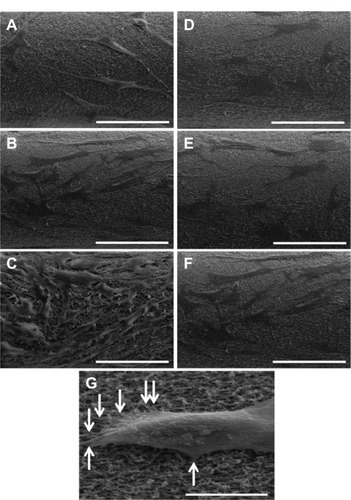
To further confirm improved cell attachment on FN/Fbg fibers, fibroblast cells attached to FN/Fbg fibers were examined using SEM at different times (24 hours, 3 days, and 5 days). After cell attachment at each time point, the microfiber was processed to obtain SEM images. The results revealed increased cell attachment with increased incubation time, as the FN/Fbg fiber cells cultured for 24 hours showed the lowest amount of cellular attachment, while the degree of cellular attachment was positively increased over time. However, the same level of increased cell attachment was not observed with bare Fbg microfibers, demonstrating that the modification of biomaterials with adhesive proteins improves cellular function and cell attachment on a polymer surface (). clearly shows the cell attachment and actin filament penetration and fibrillary extensions in Fbg fibers. In this study, we used 10 wt% fiber to exemplify cellular attachment.
Figure 9 Representative scanning electron microscopy images of cell attachment on Fbg fibers. Images A, B, and C are FN-grafted Fbg fibers showing fibroblast cell attachment and proliferation after 24 hours, 3 days, and 5 days, respectively. Images D, E, and F are bare Fbg fibers after 24 hours, 3 days, and 5 days of fibroblast proliferation, respectively, (scale bar: 100 μm). Image G shows single-cell attachment with fiber pore structures (denoted by white arrows; Scale bar: 50 μm).
Conclusion
In the current study, we demonstrated a fabrication process for Fbg microfiber scaffolds with different structural characteristics by using a cost-effective micron-sized silicone tube. The fiber diameter and structural characteristics were mainly dependent on the concentration of Fbg. The results of the Bradford protein assay showed that Fbg microfibers with a larger diameter (200 μm), and that were aligned with more nanostructures, exhibited an increased amount of FN immobilization compared to fibers made from 10 and 5 wt% Fbg, which was likely due to increased arginine- and lysine-residue exposure. These data were supported by an FT-IR study showing a peak shift towards a lower wavelength with higher peak intensity, which was assumed to be due to increased peptide-bond formation. Fluorescence microscopic images confirmed uniform FN grafting. The fibrinolytic degradation results were consistent with the results from the protein-estimation assay and FT-IR study; the 200 μm Fbg microfibers were degraded at a slower rate than the other fibers, suggesting that plasmin took a longer time to break more peptide bonds. The results of the cell proliferation study and in vitro cell cultures demonstrated that the amount of FN immobilization strongly influenced cell attachment and proliferation. Finally these findings show that the developed Fbg microfibers are biodegradable, biocompatible, and cytocompatible. Also, Fbg microfibers contain aligned nanostructures, which can enhance biomolecule encapsulation, and have an ability to accelerate cell adhesion and proliferation compared to that of more porous Fbg fibers. We believe that the 3-D tissue-engineered scaffold described here has potential for use in biomedical applications or pharmaceutical devices, such as protein-, gene-, cell-, and drug-delivery vehicles.
Acknowledgments
This work was supported by a National Research Foundation of Korea (NRF) grant funded by the Korean government (MEST) (2012R1A2A2A03046819: Development of biodegradable and biocompatible nano-patterned microfibers and microtubes for skin and vascular tissue engineering) and the GRRC program of Gyeonggi province (GRRCKyungwon 2010-A01, Development of microfluidic chip for diagnosis of disease).
Disclosure
The authors report no conflicts of interest in this work.
References
- MalafayaPBSilvaGAReisRLNatural-origin polymers as carriers and scaffolds for biomolecules and cell delivery in tissue engineering applicationsAdv Drug Deliv Rev2007594–520723317482309
- SahniAOdrljinTFrancisCWBinding of basic fibroblast growth factor to fibrinogen and fibrinJ Biol Chem199827313755475599516457
- WangZLiMYuBCaoLYangQSuJNanocalcium-deficient hydroxy-apatite–poly (ɛ-caprolactone)–polyethylene glycol–poly(ɛ-caprolactone) composite scaffoldsInt J Nanomedicine201273123313122848159
- ParizekMDouglasTENovotnaKNanofibrous poly(lactide-co-glycolide) membranes loaded with diamond nanoparticles as promising substrates for bone tissue engineeringInt J Nanomedicine201271931195122619532
- AdhirajanNShanmugasundaramNShanmuganathanSBabuMFunctionally modified gelatin microspheres impregnated collagen scaffold as novel wound dressing to attenuate the proteases and bacterial growthEur J Pharm Sci2009362–323524518952165
- NumataKKaplanDLSilk-based delivery systems of bioactive moleculesAdv Drug Deliv Rev201062151497150820298729
- RossoFMarinoGGiordanoABarbarisiMParmeggianiDBarbarisiASmart materials as scaffolds for tissue engineeringJ Cell Physiol2005203346547015744740
- SellSAWolfePSGargKMcCoolJMRodriguezIABowlinGLThe use of natural polymers in tissue engineering: a focus on electrospun extracellular matrix analoguesPolymers201024522553
- DrewAFLiuHDavidsonJMDaughertyCCDegenJLWound-healing defects in mice lacking fibrinogenBlood200197123691369811389004
- SahniAOdrljinTFrancisCWBinding of basic fibroblast growth factor to fibrinogen and fibrinJ Biol Chem199827313755475599516457
- McManusMCBolandEDSimpsonDGBarnesCPBowlinGLElectrospun fibrinogen: feasibility as a tissue engineering scaffold in a rat cell culture modelJ Biomed Mater Res A200781229930917120217
- ShachafYGonen-WadmanyMSeliktarDThe biocompatibility of Pluronic F127 fibrinogen-based hydrogelsBiomaterials201031102836284720092890
- FlanaganTCCornelissenCKochSThe in vitro development of autologous fibrin-based tissue-engineered heart valves through optimised dynamic conditioningBiomaterials200728233388339717467792
- HaycockJW3D Cell Culture: Methods and Protocols (Methods in Molecular Biology)New YorkHumana2011
- LiYYangSTEffects of three-dimensional scaffolds on cell organization and tissue developmentBiotechnol Bioprocess Eng200165311325
- HwangCMKhademhosseiniAParkYSunKLeeSHMicrofluidic chip-based fabrication of PLGA microfiber scaffolds for tissue engineeringLangmuir200824136845685118512874
- HongJKMadihallySVNext generation of electrosprayed fibers for tissue regenerationTissue Eng2011172125142
- NgRZhangXLiuNYangSTModifications of nonwoven polyethylene terephthalate fibrous matrices via NaOH hydrolysis: effects on pore size, fiber diameter, cell seeding and proliferationProc Biochem2009449992998
- KidoakiSKwonIKMatsudaTMesoscopic spatial designs of nano-and microfiber meshes for tissue-engineering matrix and scaffold based on newly devised multilayering and mixing electrospinning techniquesBiomaterials2005261374615193879
- DzenisYMaterial science. Spinning continuous fibers for nanotechnologyScience200430456791917191915218134
- LinYSHuangKSYangCHMicrofluidic synthesis of microfibers for magnetic-responsive controlled drug release and cell culturePloS One20127318
- KiCSBaekDHGangKDLeeKHUmICParkYHCharacterization of gelatin nanofiber prepared from gelatin–formic acid solutionPolymer2005461450945102
- BarnesCPSellSABolandEDSimpsonDGBowlinGLNanofiber technology: designing the next generation of tissue engineering scaffoldsAdv Drug Deliv Rev200759141413143317916396
- MarimuthuMKimSAnJAmphiphilic triblock copolymer and a microfluidic device for porous microfiber fabricationSoft Matter201061022002207
- GarciaAJVegaMDBoettigerDModulation of cell proliferation and differentiation through substrate-dependent changes in fibronectin conformationMol Biol Cell199910378579810069818
- VallieresKChevallierPSarra-BournetCTurgeonSLarocheGAFM imaging of immobilized fibronectin: does the surface conjugation scheme affect the protein orientation/conformation?Langmuir200723199745975117705411
- KhademhosseiniALangerRBorensteinJVacantiJPMicroscale technologies for tissue engineering and biologyProc Natl Acad Sci USA200610382480248716477028
- RuoslahtiEReedJCAnchorage dependence, integrins, and apoptosisCell19947744774788187171
- BarbucciRMagnaniAChiumientoAPasquiDCangioliILamponiSFibroblast cell behavior on bound and adsorbed fibronectin onto hyaluronan and sulfated hyaluronan substratesBiomacromolecules20056263864515762624
- SeidlitsSKDrinnanCTPetersenRRShearJBSuggsLJSchmidtCEFibronectin-hyaluronic acid composite hydrogels for three-dimensional endothelial cell cultureActa Biomater2011762401240921439409
- RajangamTPaikHJAnSSAFabricating fibrinogen microfibers with aligned nanostructure, as biodegradable threads for tissue engineeringBull Korean Chem Soc201233620742078
- NakajimaNIkadaYMechanism of amide formation by carbodiimide for bioconjugation in aqueous mediaBioconjug Chem1995611231307711098
- CustodioCAAlvesCMReisRLManoJFImmobilization of fibronectin in chitosan substrates improves cell adhesion and proliferationJ Tissue Eng Regen Med20104431632320049746
- CrouchSPKozlowskiRSlaterKJFletcherJThe use of ATP bioluminescence as a measure of cell proliferation and cytotoxicityJ Immunol Methods1993160181887680699
- PasseySPellegrinSMellorHScanning electron microscopy of cell surface morphologyCurr Protoc Cell Biol2007 Chapter 4: Unit 4.17
- LeeCHShinHJChoIHNanofiber alignment and direction of mechanical strain affect the ECM production of human ACL fibroblastBiomaterials200526111261127015475056
- LeeYHLeeJHAnIGElectrospun dual-porosity structure and biodegradation morphology of Montmorillonite reinforced PLLA nanocomposite scaffoldsBiomaterials200526163165317215603811
- GildnerCDLernerALHockingDCFibronectin matrix polymerization increases tensile strength of model tissueAm J Physiol Heart Circ Physiol200428714653
- SottileJHockingDCFibronectin polymerization regulates the composition and stability of extracellular matrix fibrils and cell-matrix adhesionsMol Biol Cell200213103546355912388756
- RajangamTPaikHJAnSSADevelopment of fibrinogen microspheres as a biodegradable carrier for tissue engineeringBiochip J201152175183
- TuncSMaitzMFSteinerGVázquezLPhamMTSalzerRIn situ conformational analysis of fibrinogen adsorbed on Si surfacesColloids Surf B Biointerfaces2005423–421922515893222
- LaiJYLiYTInfluence of cross-linker concentration on the functionality of carbodiimide cross-linked gelatin membranes for retinal sheet carriersJ Biomater Sci Polym Ed2011221–3277295
- LatalloZSTeisseyreEWegrzynowiczZKopécMDegradation of fibrinogen by proteolytic enzymesScand J Haematol Suppl19718S1315194258200
- NuttelmanCRMortisenDJHenrySMAnsethKSAttachment of fibronectin to poly(vinyl alcohol) hydrogels promotes NIH3T3 cell adhesion, proliferation, and migrationJ Biomed Mater Res200157221722311484184
- GrinnellFFibronectin and wound healingJ Cell Biochem19842621071166084665
- HoMHWangDMHsiehHJPreparation and characterization of RGD-immobilized chitosan scaffoldsBiomaterials200526163197320615603814
- TigliRSGumusdereliogluMEvaluation of RGD- or EGF-immobilized chitosan scaffolds for chondrogenic activityInt J Biol Macromol200843212112818485469