
Abstract
A new automated pharmacoanalytical technique for convenient quantification of redox-active antibiotics has been established by combining the benefits of a carbon nanotube (CNT) sensor modification with electrocatalytic activity for analyte detection with the merits of a robotic electrochemical device that is capable of sequential nonmanual sample measurements in 24-well microtiter plates. Norfloxacin (NFX) and ciprofloxacin (CFX), two standard fluoroquinolone antibiotics, were used in automated calibration measurements by differential pulse voltammetry (DPV) and accomplished were linear ranges of 1–10 μM and 2–100 μM for NFX and CFX, respectively. The lowest detectable levels were estimated to be 0.3±0.1 μM (n=7) for NFX and 1.6±0.1 μM (n=7) for CFX. In standard solutions or tablet samples of known content, both analytes could be quantified with the robotic DPV microtiter plate assay, with recoveries within ±4% of 100%. And recoveries were as good when NFX was evaluated in human serum samples with added NFX. The use of simple instrumentation, convenience in execution, and high effectiveness in analyte quantitation suggest the merger between automated microtiter plate voltammetry and CNT-supported electrochemical drug detection as a novel methodology for antibiotic testing in pharmaceutical and clinical research and quality control laboratories.
Introduction
Drug discovery and clinical analysis are areas in which efficient, accurate, cost-effective, and convenient analytical methods are needed. A balance between the different criteria is best reached by systematic parameter optimization for the specific detection scheme of choice and, if possible, automation.Citation1 Accomplishments in automation of electroanalysis schemes include computer-controlled microfluidic devices with voltammetric detection in flow-through electrochemical chambers,Citation2 non-manually operated electrode microarrays,Citation3 microtiter plates with multiplexed three-electrode systems on vial bottoms,Citation4 and electrochemical analyzers with robotic sampling and pipetting.Citation5,Citation6 Our own recent contribution to automatic electroanalysis is timed voltammetry, with a three-electrode assembly that moves sequentially between microtiter plate wells for nonmanual analyte determinations at user-specified points. With graphite pencil “leads” used as working electrodes (PL-WEs), this setup was capable of accurate robotic differential pulse voltammetry (DPV) of vitamin C,Citation7 automated amperometric total antioxidant capacity measurements,Citation8 and robotic trace lead and cadmium stripping voltammetry.Citation9 Motivated by pharmaceutical and clinical interest in drug assays, our next aim was to develop easily handled antibiotic analysis by microtiter plate-based voltammetry. Two antibiotics, norfloxacin (NFX) and ciprofloxacin (CFX), served as model analytes in evaluating this approach. Voltammetric antibiotic quantification is, however, often limited by poor redox conversion of this group of analytes at bare carbon or noble metal electrodes, which badly affects the onset of faradaic current signals and thus compromises sensitivity and accuracy. This can be improved by coating the sensor with materials that facilitate electron transfer for drug electroxidation or reduction.Citation10–Citation16 Based on earlier reports of success with carbon nanotube (CNT)-assisted NFXCitation17,Citation18, CFXCitation19,Citation20 and other analyteCitation22–Citation24 voltammetry, electrophoretic CNT depositionCitation21 was chosen to modify the PL-WEs in the three-electrode assembly of a robotic workstation for NFX and CFX voltammetry. Through parameter optimization for WE modification, CNT layers were obtained that enabled stable and accurate NFX/CFX detection during voltammetric microtiter plate runs.
We report the details of the sensor testing by voltammetry, results of robotic voltammetric drug calibrations in preloaded microtiter plates, and NFX/CFX quantification by robotic drug voltammetry in model, dissolved tablet, and, for NFX, human serum samples with added analyte. In contrast to previously described options for automated electroanalysis, the practice described in this study does not need complicated microfluidics or complex electrode structures. Its application in pharmacoanalytics for nonmanual antibiotic sample evaluation is thus practical, provided that the target molecules are electroactive and hence suitable for electrochemical detection.
Material and methods
Chemicals and materials
Analytical grade NFX and CFX powders were from Sigma-Aldrich GmbH (Munich, Germany) while their tablet formulations came from QUALIMED Co, Ltd (Bangkok, Thailand) (NFX, type Norfar®, 400 mg/tablet) and MILLIMED Co, Ltd (Bangkok Thailand) (CFX, type Cobay®, 500 mg/tablet). Stock solutions of 1 mM drug were prepared by dissolving their powders in 0.01 M HCl. NFX was measured in acetate buffer (0.1 M in 0.1 M KCl, pH 4.5), while phosphate buffers (0.1 M in 0.1 M KCl, pH 4.0) were used for CFX. The electrolyte for cyclic voltammetry (CV) and DPV electrode tests was 1 mM K3[Fe(CN)6] in 0.1 M KCl.NaNO3 (anhydrous, 99%) and N2 gas (99.99%, Linde Thailand, Thailand) were used to make and condition the electrolyte for the voltammetric evaluation of WE capacitances. If no specific source and quality is stated, chemicals were analytical grade and obtained via Italmar (Thailand) Co, Ltd (Bangkok, Thailand). Drug stock and test solutions and buffers used ultrapure deionized water. Human serum was made from the whole blood of a healthy volunteer following a standard isolation protocol.
Common heat-shrinking tubes, as used in electrical engineering for the isolation of wirings and joints, and 0.5-mm-diameter pencil leads (Pentel® HB, Pentel Co, Ltd, Bangkok, Thailand) from a local stationery shop were used for the fabrication of PL-WEs. The process of polymer tube sealing left ~2 mm of the pencil lead exposed at the bottom end, which brought ~3 mm2 into use as electroactive area. A 1-mm-diameter Ag wire (Goodfellow, Cambridge, UK) became the applied pseudo-Ag/AgCl reference electrode (RE) via 10-minute application of a DC voltage of 10 V vs a Pt wire in 1 M HCl/3 M KCl electrolyte, with consequent formation of a well-adhering layer of AgCl. A coiled 0.5-mm-diameter Pt wire (Goodfellow) served as counterelectrode (CE), with an immersed area of about 500 mm2. For thin-film surface modification of PL-WEs, aqueous suspensions of purified single-walled CNTs, with 1.0–3.0 at.% carboxylic acid entities (P3-SWNT; Carbon Solutions, Inc, Riverside, CA, USA), were used.
Instrumentation
The PL-WEs for NFX and CFX trials in the robotic voltammetry mode were obtained by inserting 3-cm-long pieces of the thin graphite sticks into heat-shrinking tubes of marginally larger diameter. It was ensured that 4 mm of the pencil leads projected at the top to act as contact point to the WE potentiostat cable and 2 mm came out at the bottom to serve as the sensor. A hot air stream from a laboratory heat gun was then used to trigger the desired temperature-induced tube shrinking, which, with no involvement of an inert composite sealant material as, for instance, epoxy- or silicon-based resins, reproducibly sealed the conductive microfilament into a tightly gripping polymeric cover. A home-made WE/CE/RE holder was used to form a movable three-electrode assembly, which was small enough to enter the microtiter plate vials via a micropositioning system control without the risk of damage ().
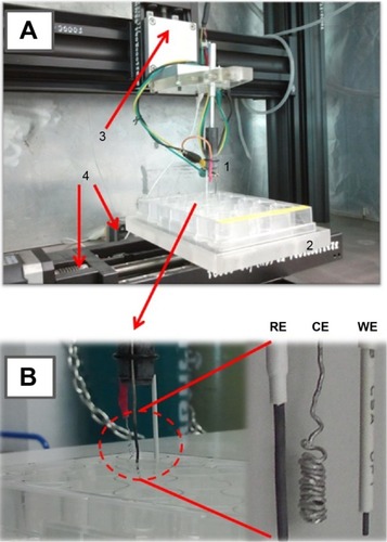
Figure 1 The device (A) for robotic antibiotic electroanalysis in 24-well microtiter plates (B).
Notes: The major components are (1) the three-electrode assembly with a pencil lead-WE, a platinum-CE (counterelectrode), and a Ag/AgCl-RE (reference electrode); (2) the microtiter plate platform; (3) the micropositioning stage for vertical movement of the electrode assembly; (4) two micropositioning stages for lateral microtiter plate movement; and (5) (not shown) a potentiostat and a personal computer for system operation and voltammetry.
Abbreviations: CE, counter-electrode; WE, working electrode; RE, reference electrode; WE, working electrode.
The potentiostat was a PalmSens® device (PalmSens BV, Utrecht, the Netherlands), and a set of computer-controlled micropositioners (Owis GmbH, Staufen im Breisgau, Germany) enabled vertical (z) electrode and horizontal (x/y) microtiter plate movements. The hardware and software of the workstation moved the electrode assembly in a user-defined sequence from well to well and made voltammetric recordings during halts of preset lengths. Manual voltammetric sensor tests used conventional beaker-type electrochemical cells and the PalmSens® potentiostat. A function generator (Agilent Technologies, Inc, Santa Clara, CA, USA) served as power supply for CNT electrodeposition on PL-WEs, and a scanning electron microscope (eSEM Dual Beam™ Quanta 3D FEG, FEI, Hillsboro, OR, USA) was used for inspection of the electrodes.
CNT modification of PL-WEs
Before use, PL-WEs were cleaned by dipping in 4 M nitric acid for 1 minute, then rinsed with deionized water, and air-dried. The electrolyte for electrical field-induced CNT deposition onto PL-WE surfaces was a 20 mg/mL suspension of the carboxylated graphitic filaments in water, ultrasonicated for 30 minutes. As illustrated in , CNT film formation on PL-WE surfaces was accomplished in a small beaker-type two-electrode cell by 10-minute application of a constant potential of +1 V, against a platinum wire CE.
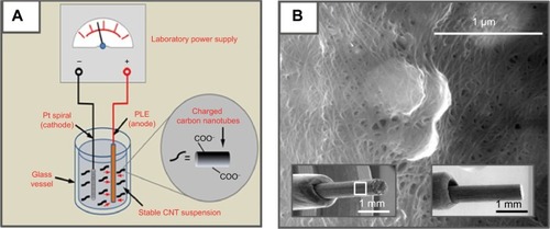
Figure 2 Modification of pencil lead electrodes with carbon nanotubes.
Notes: (A) Schematic of the electrophoretic CNT deposition procedure. At a DC voltage of +1 V for 10 minutes, a well-adhering CNT thin layer is deposited on the PLE, which is then tuned for use as the working electrode for electrochemical drug measurements in the robotic electrochemical workstation. (B) High-resolution SEM image of a randomly selected area on the surface of a CNT-modified PLE (16,000×); the bottom left and right insets are low-resolution SEM images of the CNT-modified (60×) and a bare (50×) PLE, respectively. The area of the zoom shown as part (B) was located within the white box in the left insert.
Abbreviations: PLE, pencil lead electrode; SEM, scanning electron microscopy; CNT, carbon nanotube.
Results and discussion
CNT sedimentation and defect-free thin film formation on the PL-WE substrates were first examined by SEM. In low-magnification SEM micrographs, the ultrathin superficial nanomaterial covering was not resolved and CNT-modified and bare PL-WEs appeared virtually identical (insets of ). At higher magnification, however, the dense nanoporous CNT network on the outside of treated PL-WEs became clearly evident (). Electrodeposited CNT layers were uniformly and firmly stacked on the surface of the PL-WE with no sign of cracking or delamination. The visible nanoporosity of the films suggested an increased electroactive surface area compared with the unmodified surfaces.
The results of subsequent manual voltammetric assessment of the intrinsic surface properties of bare and CNT-modified PL-WEs are shown in and . Cyclic potential scans with the electrodes in redox-mediator-free, 99.99% pure, N2-purged electrolyte produced quasi-rectangular voltammograms, typical of a purely capacitive electrode response (). As expected, the anodic and cathodic charging currents I were directly proportional to scan speed v (graphs not shown). Plots of ΔI (ie, the difference between the two currents extracted from the voltammograms at the same potential) against v were also linear (R2>0.999, and D).
Figure 3 Electrode capacitance determinations for a bare and a CNT-modified PL-WE by cyclic voltammetry in oxygen-free, N2-purged, 0.1 M NaNO3.
Notes: (A) and (C) are the original voltammograms as recorded at seven scan rates in between 20 mV/s and 200 mV/s (from inner to outer traces). Plots (B) and (D) are of the width of the quasi-rectangular CVs at 0.05 V vs Ag/AgCl, against the scan speed. Errors bars in (B) and (D) represent the standard deviation of three measurements; if not clearly visible, the bars happened to be smaller in width than the markers used for data point presentation.
Abbreviations: CNT, carbon nanotube; CV, cyclic voltammetry; PL-WE, pencil lead working electrode.
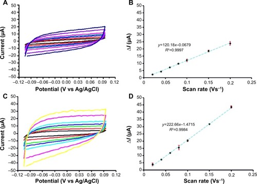
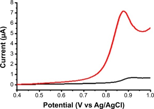
Figure 4 Ferricyanide differential pulse voltammetry with a bare (green) and a CNT-modified (red) pencil lead electrode.
Notes: The concentration of [Fe(CN)6]3− was 1 mM in 0.1 M KCl and the parameters for DPV acquisition were as follows: pulse amplitude 25 mV, pulse width 25 ms and scan speed 20 mV/s.
Abbreviations: CNT, carbon nanotube; DPV, differential pulse voltammetry.
![Figure 4 Ferricyanide differential pulse voltammetry with a bare (green) and a CNT-modified (red) pencil lead electrode.Notes: The concentration of [Fe(CN)6]3− was 1 mM in 0.1 M KCl and the parameters for DPV acquisition were as follows: pulse amplitude 25 mV, pulse width 25 ms and scan speed 20 mV/s.Abbreviations: CNT, carbon nanotube; DPV, differential pulse voltammetry.](/cms/asset/876be0e2-201e-46c5-a1cd-0a03034c06b2/dijn_a_75237_f0004_c.jpg)
Measurement of ΔI as a function of v allowed calculation of the individual electrode double-layer capacitance C from the formula C = ΔI/(2v). The average values for otherwise identical PL-WEs, with and without CNT, were 111±7 μF (n=3) and 67±5 μF (n=3), respectively. Since the capacitance of an electrode is directly proportional to its effective area, the ~1.7-fold larger C-value for the CNT-modified PL-WE confirmed the observation from SEM inspection that the porosity of the thin-layer films of the carbon filaments created an electrode structure with enlarged contact area for the electrolyte.
The increase in sensitivity produced by the CNT coating is shown in . Here we compare the standard ferricyanide DPV at bare and CNT-modified PL-WEs. In each case, there was a well-defined symmetrical current peak for the reduction of ferricyanide at the graphitic surface; however, while the peak potentials were identical, their amplitudes differed significantly, with the CNT modification producing ~2.3-fold higher cathodic redox current. Thus, the increase in surface area shown by the SEM and CV inspections of the interfacial nanotube network in and led to a clear voltammetric signal enhancement. Interestingly, a decrease in the charge transfer resistance Rct across the electrode/electrolyte interface has been reported in a number of published studies (eg, in Refs Citation22–Citation24); this effect is another advantage of the CNT electrode covering and, though not specifically studied here, may have contributed to the observed increase in the ferricyanide reduction peak current.
In preliminary manual antibiotic voltammetry trials, DPVs were recorded for NFX and CFX with a bare and a CNT-modified PL-WE. For 100 μM NFX, a representative pair of DPV traces is shown in . The bare PL-WE produced only a slight deflection for the anodic oxidation of NFX, while electroxidation at the CNT-modified PL-WE resulted in a pronounced peak, suitable for quantitative analysis. Apparently, the nanotube film enhanced the electrochemical oxidation of NFX and (data not shown) also CFX, the second antibiotic studied. Reliably, manual NFX and CFX DPV produced proportional current peaks for concentrations up to 10 μM and 100 μM, respectively. The minimum antibiotic levels producing analyzable current peaks with CNT PL-WEs as detectors were 0.3±0.1 μM (n=7) for NFX and 1.6±0.1 μM (n=7) for CFX. We concluded at this stage that operational analytical voltammetry of the selected antibiotics could be accomplished only with a current-enhancing CNT layer on the surface of the PL-WE. All subsequent robotic trials therefore used thin CNT-modified PL-WEs.
Figure 5 DPV of NFX with a bare (black) and a CNT-modified (red) pencil lead working electrode.
Notes: NFX concentration was 10 μM in 0.1 M acetate buffer (pH 4.5)/0.1 M KCl. Parameters for DPV acquisition were as follows: pulse height 25 mV, pulse width 25 ms and scan speed 20 mV/s, with 300 seconds allowed at 0.4 V vs Ag/AgCl before actual DPV initiation.
Abbreviations: CNT, carbon nanotube; DPV, differential pulse voltammetry; NFX, norfloxacin.
The establishment of robotic antibiotic voltammetry began with tests of the stability of the system’s response to the analytes through complete microtiter plate voltammetry trials. As indicated in , all sample wells in microtiter plate rows 2, 4, and 6 were filled with the antibiotic solution of a concentration within the manually determined linear response range. Use of the electrode assembly for an automated analytical plate run, with sensor cleaning between individual measuring steps, produced 12 antibiotic voltammograms (data not shown). Statistical analysis of all peak currents revealed virtually constant values for both 8 μM NFX (3.71±0.11 μA, n=12) and 50 μM CFX (2.81±0.12 μA, n=12) during the 3-hour (NFX) and 2-hour (CFX) plate runs. This superb signal stability meant that analyte degradation and sensor fouling could be excluded, at least for up to 3 hours of recording.
Figure 6 The microtiter plate well loading for robotic voltammetric NFX and CFX stability tests and calibration trials, with CNT-modified pencil lead working electrodes.
Notes: For stability tests, all wells in rows 2, 4, and 6 (including A2) contained sample solution (8 μM for NFX and 50 μM for CFX). For calibration trials, drug levels were between 0 (well A2) and 100 μM (well D6) in 0.1 M acetate (pH 4.5)/0.1 M KCl (NFX) or 0.1 M phosphate (pH 4)/0.1 M KCl (CFX) buffers. Parameters for DPV acquisition in the microtiter plate wells were as follows: pulse height and width 25 mV and 25 ms; scan range and speed 0.4–1.2 V vs RE and 20 mV/s; waiting time before DPV scan initiation 300 seconds (NFX) and 180 seconds (CFX) at 0.4 V vs RE; 25°C. Analytical runs started in well A1 (electrode pretreatment) and finished in well D6 (last sample solution).
Abbreviations: CFX, ciprofloxacin; CNT, carbon nanotube; DPV, differential pulse voltammetry; NFX, norfloxacin; RE, reference electrode.
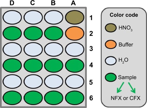
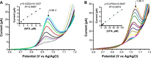
Calibration curves were acquired automatically with the microtiter plate loadings outlined in . Typical plate calibration runs began with dipping the PL-WE in HNO3 (well A1), followed by dip-cleaning in deionized H2O (well A3), and, finally the acquisition of the first voltammogram in buffer alone (well A2). The steps of acid sensor conditioning, water cleaning, and use were repeated throughout the test until all the sample wells had been tested and the resultant DPVs stored. Completion of one full plate run thus navigated the three-electrode assembly in the following sequence through the 24 individual wells: A1, A3, A2, A1, A3, A4, A1, A5, A6, A1, B1, B2, A1, B3, B4, A1, B5, B6, A1, C1, C2, A1, C3, C4, A1, C5, C6, A1, D1, D2, A1, D3, D4, D1, D5, D6. Representative sets of automatically acquired NFX and CFX DPVs and the related standard plots of the extracted voltammetric peak currents against the corresponding analyte concentrations are shown in . With the parameter set used, linearity of the DPV response, with R2 values above 0.99, was maintained up to 10 μM and 100 μM for NFX and CFX, respectively. Typical average values for the current sensitivity of CNT PL-WEs against NFX and CFX were 0.421±0.007 μA/μM (NFX, n=3) and 0.070±0.001 μA/μM (CFX, n=3). Also, the minimum detectable NFX and CFX concentrations in robotic voltammetry PL-WEs were equivalent to the measures of the manual analog. It is worth mentioning here that the current peak maxima of NFX and CFX DPVs are in the order of 100 mV distant to each other on the potential scale. This significant anodic peak separation technically would be suitable for simultaneous NFX and CFX determination; however, direct dual detection of the two drugs was not the focus of the current work but may be explored in future application of the methodology.
Figure 7 NFX (A) and CFX (B) differential pulse voltammograms from robotic calibration measurement in a 24-well microtiter plate.
Notes: The insets are plots of the peak currents as a function of antibiotic concentration. Electrolyte for in-well DPV was a 0.1 M acetate (pH 4.5)/0.1 M KCl buffer for NFX and a 0.1 M phosphate (pH 4)/0.1 M KCl buffer for CFX. DPV parameters were as follows: pulse height and width 25 mV and 25 ms; scan range and speed 0.4–1.2 V vs. RE and 20 mV/s; waiting time before DPV scan initiation 300 s (NFX) and 180 s (CFX) at 0.4 V vs RE; 25°C. Errors bars in the insets of (A) and (B) represent the standard deviation of three measurements; however, the bars are smaller in width than the markers used for data point presentation and thus do not appear clearly. The peak potentials for the highest concentrations of NFX and CFX are 0.96 and 1.06 V vs Ag/AgCl, respectively.
Abbreviations: CFX, ciprofloxacin; NFX, norfloxacin; DPV, differential pulse voltammetry; RE, reference electrode.
presents the analytical figures of merit of NFX and CFX DPV in the novel robotic mode and measured with CNT-modified PL-WEs, in comparison with equivalent data for manual voltammetric detection of the two analytes with various previously reported CNT-modified and CNT-free electrochemical sensors, which used polished disks of glassy carbon (GC), pyrolytic carbon (PC), carbon paste (CP), and gold (Au) or mercury (Hg) films on carbon or noble metal electrode disks as precursor structures. In automatic operation, the performance of CNT-modified PL-WEs reached in terms of linear range and sensitivity for both analytes about the level of the cited manual procedures. Slightly poorer detection limits and linear ranges probably reflect differences in the sensor’s base material, which was common pencil graphite in this study but GC, PC, CP, Au, or Hg in the previous reports. Graphite pencil “leads” contain up to 20% clay as added binder material, and the presence of this nonconducting inorganic ingredient may to a small extent reduce electron charge transfer on the graphitic planes across the PL-WE surfaces. Our experience showed, however, that notwithstanding this effect, the results of robotic NFX/DPV at CNT-modified PL-WEs were satisfactory, provided the target sample levels were within the detectable range. Confirmed was in the automated calibration trials an analytical performance that was as good as possible with the GC/PC/CP/Au/Hg equivalents. And reach of the indispensable signal stability of PL-WEs for the entire time of their use in the robotic electrochemical workstation was evident from robotic 2–3 hours voltammetric microtiter plate runs with, for instance, no significant current decay for the same NFX/CFX levels in all sample plate wells. This was an important new technical accomplishment because PL-WEs in terms of design and ease of fabrication turned out to be most practical for implantation into the movable three-electrode assembly of the robotic electrochemical microtiter plate assay. The potential of the methodology was thus further explored for antibiotic determinations in various test solutions. Buffer solutions of defined NFX and CFX concentrations were screened first, to test the recovery of analyte. Simulations of biological samples were made from pharmaceutical NFX and CFX formulations dissolved in the measuring buffers or from fresh human blood serum spiked with NFX.
Table 1 Comparison of analytically relevant figures of merit of different electrochemical strategies for the quantitative determination of NFX and CFX
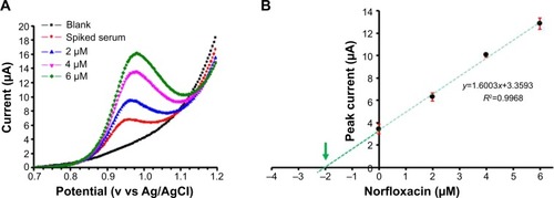
Microtiter plate loading for robotic voltammetric antibiotic quantification in the standard addition mode is shown in . The wells in row 1 contained HNO3 (A1) and H2O (B1, C1, D1) and all vessels in row 2 contained buffer solution. The wells in the rows 3–6 contained the samples, either untreated or spiked with antibiotic. With this layout, the four samples could be processed in 3-hour (NFX) or 2-hour (CFX) automated runs, without any operator involvement. A representative example of the resulting raw data is shown in as a set of four DPVs that were successively acquired during robotic NFX determination in human blood serum. A plot of the peak currents of the presented DPVs against added NFX levels was linear (), and the regression line (R2=0.997) extrapolation to zero current and/or a calculation based on the corresponding line equation (y=1.61x+3.36) allowed determination of the endogenous NFX level in the original sample. Actually, the final concentration of NFX added to the serum was 2.00 μM, while that measured was 2.09 μM. The recovery, defined here as the ratio of the value obtained from robotic DPV analysis divided by the known value of serum sample supplementation, was thus 103.5%±5.1%. The outcome of all robotic voltammetry NFX and CFX sample measurements, in terms of apparent recoveries, is summarized in . Values in the range 97%–104% recovery were consistent with the standard method performance requirements recommended by the Association of Analytical Communities for the range of analyte concentration.Citation35 Thus, the quality of the proposed automated electrochemical microtiter plate assay, with CNT-modified PL-WEs, was comparable with traditional manual voltammetric methods for measuring the two chosen antibiotics. The convenience of automation is an additional asset, and use of the proposed methodology for analysis of sample libraries is thus feasible.
Table 2 Recoveries from robotic microtiter plate voltammetry of NFX and CFX in supplemented prototype, dissolved tablet, and spiked serum samples
Figure 8 Microtiter plate loading as used for robotic voltammetric NFX and CFX quantification trials with CNT-modified pencil lead working electrodes and the standard addition method.
Notes: Electrolyte for in-well DPV was a 0.1 M acetate (pH 4.5)/0.1 M KCl buffer for NFX and a 0.1 M phosphate (pH 4)/0.1 M KCl buffer for CFX. DPV parameters were as follows: pulse height and width 25 mV and 25 ms; scan range and speed 0.4–1.2 V vs. RE and 20 mV/s; waiting time before DPV scan initiation 300 s (NFX) and 180 s (CFX) at 0.4 V vs RE; 25°C. Analytical runs started in well A1 (electrode pretreatment) and ended in well D6 (last sample solution).
Abbreviations: CFX, ciprofloxacin; CNT, carbon nanotube; DPV, differential pulse voltammetry; NFX, norfloxacin; SA, standard addition; RE, reference electrode.
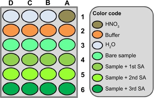
Figure 9 Robotic voltammetric quantification of NFX in spiked human serum samples by the standard addition method.
Notes: A set of four DPVs for buffer alone, a serum sample with 2 mM NFX supplementation, and the solution with three additions of NFX, all acquired in an automated run through a loaded microtiter plate (A). Standard addition curve and linear regression plot (B). Electrolyte for in-well NFX-DPV was a 0.1 M acetate (pH 4.5)/0.1 M KCl buffer. DPV parameters were as follows: pulse height and width 25 mV and 25 ms; scan range and speed 0.4–1.2 V vs. RE and 20 mV/s; waiting time before DPV scan initiation 300 s at 0.4 V vs RE; 25°C. Errors bars in (B) represent the standard deviation of three measurements; however, the error bar for the 4 μM data point is smaller in width than the marker used for data point presentation and thus does not appear clearly. The green arrow points toward the x-axis interception, which represents the actual analyte concentration of the inspected sample.
Abbreviations: DPVs, differential pulse voltammograms; NFX, norfloxacin; RE, reference electrode.
Conclusion
A novel microtiter plate-based robotic voltammetric antibiotic assay that uses CNT-modified PL-WEs as tailored sensors for analyte quantification has been developed. For two model antibiotics, NFX and CFX, the automated electroanalysis offered good response stability and a practical linear response range. Near-perfect recoveries during measurements of standard solutions, dissolved pharmaceutical tablets, and spiked human serum samples confirmed the reliability of the methodology. An important factor in achieving this electroanalytical performance was the modification of the working electrode surface with a thin film of CNTs, as only then was reliable electrochemical antibiotic detection possible. Simple automation of the voltammetric analytical procedure microtiter plate stage conferred the additional benefits of manual error exclusion, convenience, and operator time-saving. In summary, this novel analytical approach may be a useful alternative to labor-intensive, manual, multiple-sample antibiotic screening in pharmaceutical work and, considering that antibiotics are ubiquitous pollutants of ground and surface water and soil,Citation36,Citation37 valuable also for application to large sets of environmental samples in governmental and private control and protection agencies. In relation to the current worldwide fears about the dramatic rise in the number of multidrug-resistant infectious microorganismsCitation38 and the related global “apocalyptic” threat of unchecked antibiotic resistance development by bacterial pathogens,Citation39 our planned future work will target applications in pharmaceutical and environmental antibiotic studies and also address the utilization of the technique for the pharmacokinetic study of bacterial antibiotic efflux pumps.
Acknowledgments
The authors wish to thank the Suranaree University of Technology (SUT) for funding of this project with research grant SUT1-102-54-12-14. They are grateful to the Biochemistry Laboratory of SUT’s Center for Scientific and Technological Equipment for general support. The National Research Council of Thailand (NRCT) is thanked for sponsoring the robotic workstation through the “High-throughput screening/analysis: Tools for drug discovery, disease diagnosis and health safety” scheme. WS additionally received financial support from The Thailand Research Fund (grant no RMU5380055), and AS gratefully acknowledges financial support from the Thailand Research Fund (TRF) through Grant TRF-BRG568000013. All authors also express their sincere thanks to Dr David Apps, Biochemistry Reader (retired), Centre for Integrative Physiology, Edinburgh University, Scotland, for a critical reading of the manuscript and valuable language improvements, and Prof. Wolfgang Schuhmann and Sandra Schmidt from the Ruhr University Bochum, Bochum, Germany, for their help with the SEM inspection of PL-WE surfaces.
Disclosure
The authors report no conflicts of interest in this work.
References
- StanleyRAutomation in analytical chemistry – from rule of thumb to fully automated methods. Some philosophies and social consequencesJ Auto Chem19846613
- ChailapakulONgamukotPYoosamranASiangprohWWangfuengkanagulNRecent electrochemical and optical sensors in flow-based analysisSensors2006613831410
- SeidelMNiessnerRAutomated analytical microarrays: a critical reviewAnal Bioanal Chem20083911521154418504563
- LeyCZengin CekicSKochiusSAn electrochemical microtiter plate for parallel spectroelectrochemical measurementsElectrochim Acta20138998105
- HynekDPrasekJBusinovaPAutomated voltammetric determination of lead (II) ions using sensor arrayInt J Electrochem Sci2013844414446
- KremplovaMKrejcovaLHynekDAutomated electrochemical detection of iron ions in erythrocytes from MeLiM minipigs suffering from melanomaInt J Electrochem Sci2012758935909
- IntarakamhangSLesonCSchuhmannWSchulteAA novel automated electrochemical ascorbic acid assay in the 24-well microtiter plate formatAnal Chim Acta20116871621241840
- IntarakamhangSSchulteAAutomated electrochemical free radical scavenger screening in dietary samplesAnal Chem2012846767677422881402
- IntarakamhangSSchuhmannWSchulteAA robotic heavy metal anodic stripping voltammetry: ease and efficacy for trace lead and cadmium electroanalysisJ Solid State Electrochem20131715351542
- ZhangFGuSDingYZhangZLiLA novel sensor based on electropolymerization of β-cyclodextrin and L-arginine on carbon paste electrode for determination of fluoroquinolonesAnal Chim Acta2013770536123498686
- OjaniRRaoofJBZamaniSA novel voltammetric sensor for amoxicillin based on nickel-curcumin complex modified carbon paste electrodeBioelectrochemistry201285444922243788
- PengJYHouCTLiuXXLiHBHuXYElectrochemical behavior of azithromycin at graphene and ionic liquid composite film modified electrodeTalanta20118622723222063535
- JainRRatherJAVoltammetric determination of antibacterial drug gemifloxacin in solubilized systems at multi-walled carbon nanotubes modified glassy carbon electrodeColloids Surf B Biointerfaces20118334034621177081
- VegaDAgüíLGonzález-CortésAYáñez-SedeñoPPingarrónJMVoltammetry and amperometric detection of tetracyclines at multi-wall carbon nanotube modified electrodesAnal Bioanal Chem200738995195817671781
- LoetanantawongBSuracheepCSomasundrumMSurareungchaiWElectrocatalytic tetracycline oxidation at a mixed-valent ruthenium oxide-ruthenium cyanide-modified glassy carbon electrode and determination of tetracyclines by liquid chromatography with electrochemical detectionAnal Chem2004762266227215080737
- EnsafiAAAllafchianARRezaeiBA sensitive and selective voltammetric sensor based on multiwall carbon nanotubes decorated with MgCr2O4 for the determination of azithromycinColloids Surf B Biointerfaces201310246847423261568
- DevarajMDeivasigamaniRKJeyadevanSEnhancement of the electrochemical behavior of CuO nanoleaves on MWCNTs/GC composite film modified electrode for determination of norfloxacinColloids Surf B Biointerfaces201310255456123104025
- HuangKJLiuXXieWZYuanHXElectrochemical behavior and voltammetric determination of norfloxacin at glassy carbon electrode modified with multi walled carbon nanotubes/nafionColloids Surf B Biointerfaces20086426927418358704
- FotouhiLAlahyariMElectrochemical behavior and analytical application of ciprofloxacin using a multi-walled nanotube composite film-glassy carbon electrodeColloids Surf B Biointerfaces20108111011420655184
- EnsafiAATaeiMKhayamianTHasanpourFSimultaneous voltammetric determination of enrofloxacin and ciprofloxacin in urine and plasma using multiwall carbon nanotubes modified glassy carbon electrodes by least-squares support vector machinesAnal Sci20102680380820631443
- BoccacciniARChoJRoetherJAThomasBJCMinayEJShafferMSPElectrophoretic deposition of carbon nanotubesCarbon NY20064431493160
- GongZQSujariANAAb GhaniSElectrochemical fabrication, characterization and application of carboxylic multi-walled carbon nanotube modified composite pencil graphite electrodesElectrochim Acta201265257265
- VuralTKuralayFBayramCAbaciSDenkbasEBPreparation and physical/electrochemical characterization of carbon nanotube-chitosan modified pencil graphite electrodeAppl Surf Sci2010257622627
- KalacharHCBNayakaYAVinayakaKSViswanathaRVasanth KumarMSElectrochemical studies on usnic acid from Usnea pseudosinensis using multi walled carbon nanotube modified pencil graphite electrodeInt J Anal Bioanal Chem20122179184
- AgrawalBChandraPGoyalRNShimYBDetection of norfloxacin and monitoring its effect on caffeine catabolism in urine samplesBiosens Bioelectron20134730731223587793
- WangZLiJLiuXYangJLuXPreparation of an amperometric sensor for norfloxacin based on molecularly imprinted grafting photopolymerizationAnal Bioanal Chem20134052525253323307131
- GoyalRNSingh RanaARChastaHElectrochemical sensor for the sensitive determination of norfloxacin in human urine and pharmaceuticalsBioelectrochemistry201283465121930437
- ReddyTMBalajiKReddySJVoltammetric behavior of some fluorinated quinolone agents and their differential pulse voltammetric determination in drug formulations and urine samples using a β-cyclodextrin-modified carbon-paste electrodeJ Anal Chem200762168175
- NiYWangYKokotSSimultaneous determination of three fluoroquinolones by linear sweep stripping voltammetry with the aid of chemometricsTalanta20066921622518970557
- GhoneimMMRadiABeltagiAMDetermination of norfloxacin by square-wave adsorptive voltammetry on a glassy carbon electrodeJ Pharm Biomed Anal20012520521011275429
- EnsafiAAAllafchianARMohammadzadehRCharacterization of MgFe2O4 nanoparticles as a novel electrochemical sensor: application for the voltammetric determination of ciprofloxacinAnal Sci20122870571022790374
- ZhangXWeiYDingWElectrocatalytic oxidation and voltammetric determination of ciprofloxacin employing poly(alizarin red)/graphene composite film in the presence of ascorbic acid, uric acid and dopamineAnal Chim Acta2014835293624952626
- ZhangSWeiSElectrochemical determination of ciprofloxacin based on the enhancement effect of sodium dodecyl benzene sulfonateBull Korean Chem Soc200728543546
- IonescuREJaffrezic-RenaultNBouffierLImpedimetric immunosensor for the specific label free detection of ciprofloxacin antibioticBiosens Bioelectron20072354955517826084
- The Association of Analytical Communities (AOAC)Guidelines for single laboratory validation of chemical methods for dietary supplements and botanicals2013 Available from: http://www.eoma.aoac.org/app_k.pdf. Download from November, 2013
- KümmererKAntibiotics in the aquatic environment – A review – Part IChemosphere20097541743419185900
- LiWCOccurrence, sources, and fate of pharmaceuticals in aquatic environment and soilEnviron Pollut201418719320424521932
- WoolhouseMFarrarJAn intergovernmental panel on antimicrobial resistanceNature201450955555724877180
- TorjesenIAntimicrobial resistance presents an “apocalyptic” threat similar to that of climate change, CMO warnsBMJ2013346f159723479594