
Abstract
Calcium silicate (CS) ceramic is a good coating candidate for biomedical implants to improve biocompatibility and accelerate early osseointegration. However, the poor fracture toughness and wear resistance of this ceramic material restricts the long-term performance of implants. In this study, graphene plates (GPs) were used as reinforcement to improve the mechanical properties of CS coating. Composite coating containing 1.5 weight % GPs was prepared by vacuum plasma spraying technology. The good survival of the GPs in the composite coating was demonstrated by Raman analysis, although the defects of the GPs were increased after plasma spraying. Effects of the GPs’ adoption on the microstructure of the coating were studied by scanning electron microscopy and transmission electron microscopy. Results showed that the GPs were homogenously distributed in the CS grains interface or enwrapped on the particles, and exhibited good wetting behavior with the CS matrix. The wear properties of the composite coating were obviously enhanced by the reinforcement of GPs. The reinforcement mechanism was attributed to the enhanced micro-hardness and interfacial bonding of the particles in the coating. In vivo experiments demonstrated that the composite coating possessed similarly good biocompatibility compared to pure CS coating. The bone-implant contact ratio reached 84.3%±7.4% for GPs/CS coating and 79.6%±9.4% for CS coating after 3 months’ implantation.
Introduction
For an ideal coating material in orthopedic applications, comprehensive properties including good biocompatibility, high bonding strength with substrate, and excellent wear resistance are needed. Resulting from the insufficient initial fixation and movement of the limb, micro-vibration of total hip implant is ineluctable.Citation1,Citation2 Rough surfaces fabricated by plasma spraying has been widely used in clinical practice as an attempt to improve the mechanical compatibility and early fixation of the implants.Citation3,Citation4 Hydroxyapatite (HA) is the widely used coating material because of its similar inorganic components as the natural bone and excellent biocompatibility.Citation5,Citation6 However, the relatively rapid degradation of HA coating in biological environment due to the low crystallinity, poor bonding strength with metal substrates, and poor wear resistance affects its long-term performance.Citation7,Citation8
Calcium silicate (CS) coatings show not only good biocompatibility but also excellent bonding strength with Ti alloy substrate. They are suitable coating material candidates for load-bearing implants.Citation9,Citation10 Silicon, one of the main components of CS, is an essential trace element in animal nutrition and has very important functions in the early stage of bone and ligament tissue formation.Citation11 Hydrated silica gel can enhance the proliferation of osteoblasts and activates the production of transforming growth factors.Citation12,Citation13 Ca is also an important composition element of bone tissues. Ca ions’ implantation in Ti not only improved the spreading and attachment of MG-63 cells,Citation14 but also enhanced the growth of bone tissue in vivo.Citation15,Citation16 However, the intrinsic brittleness and mechanical unreliability of the CS ceramic restricts the long-term performance of the implants. Particulate debris produced by the micro-movements is harmful to the stable fixation of implants.
Graphene is the basic structural unit of C allotropes, such as graphite, C nanotubes and fullerenes. It is a single layer of C atoms packed in a honeycomb crystal lattice. Because of its high specific surface area, aspect ratio, tensile strength, thermal and electrical conductivity and flexibility, graphene is a preferred nanofiller compared to other conventional C materials, such as nanotube, nanofiber, expandable graphite, etc.Citation17–Citation19 The intrinsic strength and Young’s modulus of graphene is similar or slightly higher than the defect-free nanotube.Citation20 Its thermal conductivity is the highest among the other known materials up until now.Citation2 In addition to the widely used application as nanofillers in polymers, graphene is also a good reinforcement for ceramic materials.Citation21,Citation22 Si3N4 ceramic with 1.5 volume % graphene addition obtained by spark plasma sintering showed significantly enhanced fracture toughness up to 6.6 MPa·m1/2 (nearly 235% higher than pure Si3N4)Citation23. The flexural strength and fracture toughness of the graphene doped alumina ceramic were enhanced 30.75% and 27.20%, respectively. HA ceramic containing 1.0 weight (wt) % graphene exhibited ~80% improvement in fracture toughness.Citation24 The main toughening mechanisms which originated from the presence of the graphene are contributed to grain bridging, crack bridging, and crack deflection.
Graphene shows not only excellent mechanical properties but also good biocompatibility. It was widely used in biomedical applications for improving mechanical/electrical properties of biomaterials and accelerating the early cell responses, etc. Application fields include biomedical engineering, regenerative medicine and biotechnology.Citation25,Citation26 The behaviors of human osteoblasts and human marrow stem cells (hMSCs) were significantly enhanced on the graphene surface compared to those on the SiO2 substrates.Citation27 A significant improvement of osteoblasts’ adhesion and apatite mineralization was obtained by graphene adoption in HA ceramic.Citation24 A series of titania/graphene nanocomposites were synthesized using in situ sol–gel method and were used for repairing bone defects.Citation28 An enhanced human cell attachment was obtained. In our previous work, various ratios of graphene were used to reinforce CS coating.Citation29 Preliminary in vitro cytocompatibility evaluation was performed using hMSCs. Results showed that the composite coating possessed similar cytocompatibility compared to the pure CS coating.
In the present work, 1.5 wt % graphene plates (GPs) were added to CS powder. The composite powder was applied to fabricate a coating on Ti alloy substrates using vacuum plasma spraying technology. Effects of the GPs’ adoption on the microstructure and wear properties of the CS coating were studied. In vivo biocompatibility of the composite coating was evaluated using a New Zealand White rabbit model.
Experimental processes
Preparation and characterization of the composite coatings
CS powders were prepared by sol–gel process using reagent-grade Ca nitrate tetrahydrate (Ca(NO3)2·4H2O) and tetraethoxysilane (Si(OC2H5)4, TEOS, 98.0%) with an initial CaO/SiO2 molar ratio of 1.0. In brief, Ca nitrate tetrahydrate and TEOS mixture was hydrolyzed via the sequential addition of 2 M HNO3 and absolute ethanol. After mixing by vigorous stirring for 5 hours, the obtained suspension was aged overnight, and dried at 105°C for 48 hours. The CS powder was obtained by calcination of the dried gel at 800°C for 3 hours. The resultant powders were ground and sifted through a 150 mesh, and used for preparation of composite powders.
Mechanical ball milling technique was performed for homogeneous dispersion of 1.5 wt % GPs (thickness =5~20 nm, XF Nano, Nanjing, People’s Republic of China) in CS powder. In detail, GPs were first dispersed in N,N-Dimethylformamide (DMF) and sonicated for 30 minutes. And then, CS powder was added and sonicated for another 20 minutes. The composite suspension was then ball milled at 200 rpm in a planetary ball mill for 6 hours to produce a powder mixture. The GP/CS composite coating with Ti-6Al-4V as substrates was deposited by vacuum plasma spraying system (Sulzer Metco, Wohlen, Switzerland).
The microstructure of the powders and coatings was observed using scanning electron microscopy ([SEM] JSM-6700F; JEOL, Tokyo, Japan). The phase composition was examined by X-ray diffraction ([XRD] RAX-10; Rigaku, Tokyo, Japan), using Cu Kα (λ=0.154056 nm) radiation at 40 kV and 100 mA. The GPs in the composite coating was analyzed by DXR Micro-Raman spectroscopy (Thermo Fisher Scientific, Waltham, MA, USA) and transmission electron microscopy (TEM) (JSM, 2100F, JEOL).
Hardness and tribological behaviors of the coating
Effects of the GPs’ addition on the hardness of the coating were measured by a micro-hardness tester (Model HX-1000, Shanghai Aolong Xingdi Testing Instrument Co. Ltd., Shanghai, People’s Republic of China). A load of 1.96 N (200 g) for 15 seconds (s) was applied for the indentation. The average values of 30 test data are reported.
Tribological properties of the coating were measured on a micro-tribometer tester (UMT-3; Bruker Corporation, Capbell, CA, USA) with a ball-on-disc model. The wear load was assigned at 10 N after comprehensive consideration of the human body mass and test condition. A stainless steel ball was used as the counter surface. The wear debris and track were observed by SEM.
In vivo biocompatibility experiments
New Zealand White rabbits (male, 3 months old, 2.5–3.0 kg) were used for in vivo biocompatibility evaluation and the femur condyle defect model was employed. The use of animals and the experimental protocols were approved by the Institutional Animal Welfare Committee of Shanghai Jiao Tong University. Rabbits were anesthetized by injecting 3% Nembutal (30 mg/kg) via the ear vein and a longitudinal incision was made by scalpel in the rabbit femur under rigorous aseptic conditions. Defects in each femoral condyle were made by a Ø2 mm drill toward the medial epicondyle orientated perpendicular to the longitudinal and sagittal axes.Citation30 Ten implants (2×10 mm) coated with GP/CS coating (with similar number of CS coated samples for comparison) were sterilized and implanted. To avoid wound infection, each animal was given an intramuscular injection of 400,000 U penicillin per day for 3 days after operation.
At 1 and 3 months post-implantation, the rabbits were first anesthetized with 3% Nembutal, and then sacrificed by injecting air into the heart. Body tissue around the implants was obtained. The samples were fixed in 4% paraformaldehyde buffer in phosphate-buffered saline for 10 days and then dehydrated using an ascending series of alcohol (75%, 95%, and 100%, increasing every 3 days). The dehydrated sample was embedded in Technovit 7200VLC (Exakt, Norderstedt, Hamburg, Germany) for 10 days, and then polymerized for 2 days by the EXAKT 520 Light Polymerization System (Exakt). Sectional samples (50 mm) were obtained perpendicular to the implants and stained by picric acid fuchsin staining for histological observation. A semi-automatic image analysis system (BIOQUANT) was applied for measuring the amount of bone-implant contact (BIC). BIC levels were defined as the fraction of direct bone apposition at the surface of the implant. The values were the mean of five samples.
Results and discussion
Characteristics of the coating
The SEM morphologies of the feedstock and sprayed composite coating are shown in . It can be seen in that the feedstock particles were aggregated by many small CS particles and GPs. The GPs were well dispersed and mixed homogenously with the CS powder as shown in . The small CS particles were adhered together by the GPs. SEM morphology of the GPs/CS coating show a typical hierarchical structure with a lot of nanoscaled particles adhering on the relatively large particle surface (). This kind of hierarchical hybrid structure was reported to be beneficial to the biological performance of the coating.Citation31,Citation32
Figure 1 SEM views of the GPs/CS composite feedstock and as-sprayed coating.
Notes: (A) SEM morphology of the composite powder; (B) shows high magnification of (A). (C) Surface topography of the sprayed GPs/CS composite coating. (D) and (E) show the GPs in the composite coating.
Abbreviations: SEM, scanning electron microscopy; GPs, graphene plates; CS, calcium silicate.
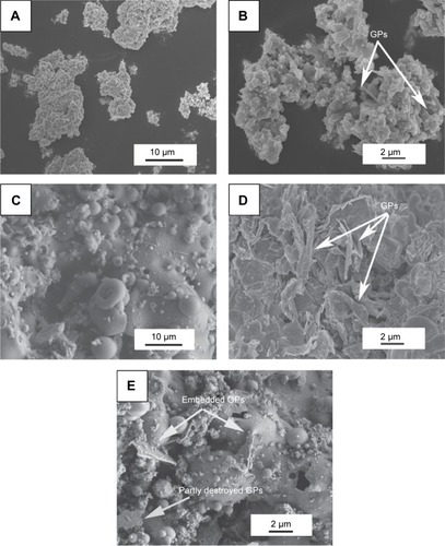
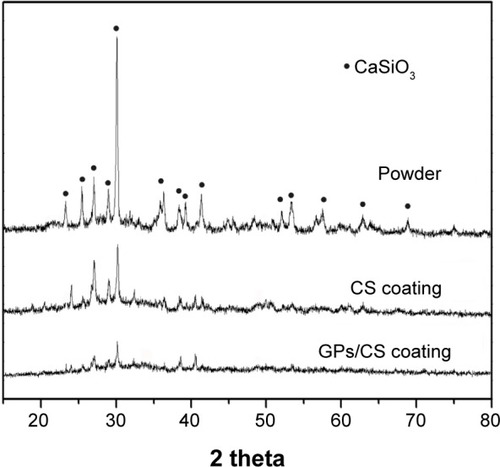
The GPs should good survival after the plasma spraying process and exhibited good wetting behaviors with the CS matrix as demonstrated in . Most of them were homogenously distributed in the CS grain interface or semi-enwrapped in the CS particles. However, no C peaks were found on the XRD spectra of the as-sprayed GPs/CS coating () or the feedstock. It may be explained by the relatively low doping amount of the GPs and low strength of the C peaks. The XRD patterns presented in indicate that only CS peaks (wollastonite-2M, JCPDS card: no 43-1460) could be detected. In addition, an obvious glass bulge coexisted with the sharp peaks of wollastonite for the coatings. The peak strength of the GPs/CS coating was the lowest among the three spectra. It may be contributed to the good thermal conductivity of the GPs and rapid heating and cooling of the composite coating in the plasma spraying process.
Figure 2 XRD patterns of the GPs/CS composite powder, CS and GPs/CS coatings.
Abbreviations: XRD, X-ray diffraction; GPs, graphene plates; CS, calcium silicate.
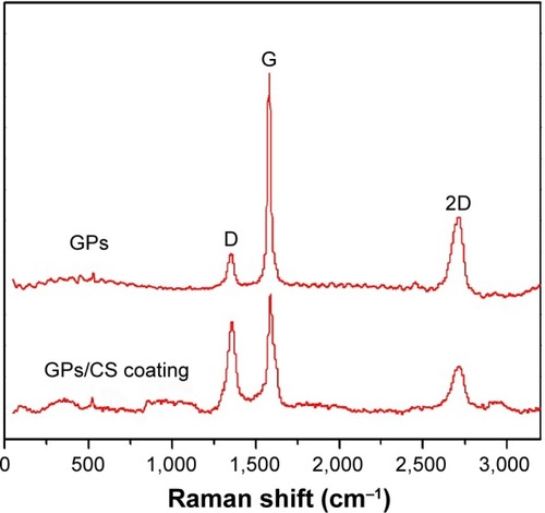
To further detect the GPs’ existence in the coating, Raman analysis was performed in this study. The G and D peaks in the Raman spectra are the straightforward demonstration of the existence and “molecular” picture of C materials.Citation33 The peak at 1,580 cm−1 (G-band) is due to the bond stretching of all pairs of spCitation2 atoms in both rings and chains, while the D peak (at 1,350 cm−1) represents the breathing modes of spCitation2 atoms in rings.Citation34,Citation35 From the Raman spectra shown in peaks confirmed the retention of C materials in the plasma sprayed coating. The D peak strength indicates the number of defects in the C materials.Citation33 Increased D peak strength means increased defect density and edges. In , the D peak strength increased significantly in the as-sprayed coating, which indicated that the defects increased after the plasma spraying process. It may be explained by the high temperature of plasma spraying or mechanical exfoliation in the ball milling process. Obviously decreased ID/IG values were observed for the GPs after plasma spraying. Reduction of ID/IG ratio meant the graphitization of GPs in the composite coating. Similar purification and graphitization for C nanotubes were also reported.Citation36–Citation40 Due to the high temperature process of plasma spraying, the C atoms diffuse to decrease the surface area of GPs and to lower the surface free energy.
Figure 3 Raman patterns of the pure GPs and GPs/CS composite coating.
Abbreviations: GPs, graphene plates; CS, calcium silicate.
Micro-hardness and tribological behavior of the coating
Good wear resistance is not only beneficial to the mechanical fixation of load bearing implants, but also the requirement for long-term biological performance. Wear debris produced from the implants may lead to harmful results. The foreign elements from the wear debris affect the viability of osteoblasts at the implant surface,Citation41 release bone-resorbing mediators stimulating excess osteoclastic differentiation,Citation42–Citation46 and finally result in osteolysis and implant loosening. In this study, the debris generated in the wear process of GPs/CS and CS coatings was measured by a pin-on-disc model with a load of 10 N and sliding distance of 500 m. A stainless steel ball was used as the sliding counter. The GPs/CS coating exhibited an obvious enhancement of wear resistance by the adoption of GPs. The mass loss of the GPs/CS coating was only 1.3±0.2 mg, while that of the pure CS coating reached up to 28.6±0.5mg.
The wear properties of materials are closely related to the hardness. The micro-hardness of the composite coating was measured in this study. The measured values for CS and GPs/CS coatings are 2.5±0.3 GPa and 2.8±0.4 GPa, respectively. With the high micro-hardness of GPs, uniform distribution, and good interfacial bonding with the CS matrix, the micro-hardness of the GPs/CS coating exhibited a 12% enhancement compared to that of the pure CS coating.
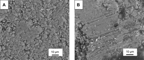
In order to investigate the wear mechanism of the coatings, wear surfaces and debris generated during the wear processes were observed by SEM. Most of the debris generated from the CS coating exhibited brittle cracked particles, while those from the GPs/CS coating showed largely aggregated particles or chipping flakes (as shown in ). Most of the wear surface of CS coating showed rough topography. Large areas of smooth regions could barely be found (). Only a homogeneously distributed small area of smooth surface formed by the worn flat asperities of the coating was detected. As we know, when the stainless steel ball slid over the coating with splats, micro-level holes and cracks, the asperities were removed in the sliding process, and a small smooth surface was formed. At the same time, a lot of pits formed by the pores or removed particles in the CS coating. This kind of wear surface was considered to be the consequence of the brittleness of CS ceramic and weak bonding of the half- or non-melted particles. For the pure CS coating, the main removing mechanism is abrasive or brittle fracture. For the GPs/CS coating, large areas of smooth surfaces could be detected widely. The pits formed by the pores or removal of particles decreased dramatically after the adoption of GPs. Wear tracks could also be detected. Although the brittle fracture still played a major role in the wear process of GPs/CS coating, a much lower mass loss was detected in the wear tests for GPs/CS coating. The enhanced wear resistance may be related to the improved interfacial bonding in the GPs/CS coating and the smooth surface or transfer layer formed by the compacted debris.
Figure 4 SEM views of the wear debris.
Notes: SEM views of the wear debris CS coating (A) and GPs/CS coating (B).
Abbreviations: SEM, scanning electron microscopy; GPs, graphene plates; calcium silicate.
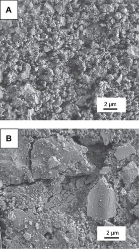
Figure 5 Wear track morphologies.
Notes: Wear track morphologies of the CS (A) and GPs/CS coatings (B).
Abbreviations: GPs, graphene plates; CS, calcium silicate.
To further study the effects of GPs’ adoption on the microstructure and mechanical properties of the composite coating, TEM was carried out to observe the microstructure of the composite coating. is the representative TEM and high resolution TEM images of the composite coating containing 1.5 wt % GPs. reveals that the GPs were uniformly dispersed in the interface or were semi-enwrapped on the CS grains. Some of the GPs were found to bridge the ceramic grains (as shown in ). High resolution TEM results show that the thickness of the GPs was about 10 nm (). Most of the GPs remained whole with a clear interface with CS grains. However, some of the GPs were also exfoliated in the mechanical ball milling or high temperature process of plasma spraying (). The internal structure of the GPs and interface with the CS grains became vague. These results directly demonstrated the increased defects of GPs after plasma spraying and higher D peak strength in the composite coating.
Figure 6 TEM observations of the GPs in the composite coating.
Notes: (A) Shows that the GPs existed in the interface or were semi-wrapped on the CS particles, and (B) exhibits that the GPs bridged the CS particles. The thickness of the GPs is about 10 nm (C), while some GPs were also exfoliated during the processes of plasma spraying or mechanical mixture (D). The arrows in (C) and (D) point out the thickness of one piece of graphene plate; and the interface between the graphene plate and calcium silicate is clear in the composite powder, while after spraying, some of the graphene plates were exfoliated.
Abbreviations: TEM, transmission electron microscopy; GPs, graphene plates; CS, calcium silicate.
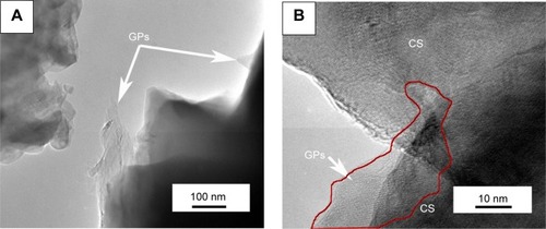
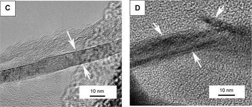
A combination of the SEM views and TEM observation demonstrated the good wetting behavior of the GPs with CS ceramic and excellent reinforcement for the improvement of mechanical properties. The uniform dispersion and high surface area of GPs impart uniform sites for energy release and high fracture toughness of the coating, and therefore the relatively high wear resistance. Kvetková et al also reported that the GPs’ adoption was beneficial to the crack deflection, slowing down of crack propagation, crack bridging, and dissipation of crack energy.Citation22
Biocompatibility evaluation in vivo
In the earlier paper, we demonstrated the good in vitro biological performance of the GPs’ reinforced CS coating.Citation29 The proliferation and osteogenesis-related genes’ (ALP, OC, OPN) expression of hMSCs on the GPs/CS coating was apparently higher than those on the Ti controls, and showed similar trends with the CS coating. In the present work, we further evaluated the in vivo biocompatibility of the composite coating. Our results show that the two coatings exhibited similarly excellent capability for the stimulation of new bone formation. The gaps between the implant and host bone tissue became progressively narrower over the implantation time. After implantation for 1 month, most of the pores on the implant surface were occupied by the bone tissue. The newly formed bone tissues were in direct contact with the coatings. However, some coating fragments could be found in the interface of the CS coating and bone tissues (as shown in ), while this kind of fragments were very little in the interface of GPs/CS coating and bone tissues. It may be explained by the increased stability of the GPs/CS coating as the reinforcement of GPs. The BIC values analyzed by the histological images were 43.5%±6.2% for GPs/CS coating and 39.8%±8.7% for CS coating. No significant difference was found between the two kinds of coating implants.
Figure 7 Histological sections of the CS coating (A) and GPs/CS coating (B) after implantation for 1 M and 3 M.
Abbreviations: M, month(s); GPs, graphene plates; CS, calcium silicate.
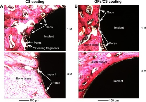
After 3 months’ implantation, pores in the interface of the implants and host bone tissue became less and pore size became smaller. Newly developed bone nearly filled all of the gaps between implants and host bone tissue. Very small pores could still be found in the interface of the CS coating and host bone, while those in the GPs/CS coating interface were even less. The measured BIC values were 84.3%±7.4% for GP/CS coating and 79.6%±9.4% for CS coating.
Conclusion
CS reinforced with 1.5 wt % GPs was prepared by vacuum plasma spraying technology. SEM and TEM results showed that the GPs survived the hot process of plasma spraying well, and were homogenously distributed in the CS grains’ interface or enwrapped on the particles. Raman analysis demonstrated that the defects in GPs obviously increased after plasma spraying. The GPs/CS composite coating showed significantly increased wear resistance compared to the pure CS coating. The removing mechanism of the CS coating was mainly abrasive or brittle fracture, while the adoption of GPs effectively improved the particle interfacial bonding and mitigated the brittle facture dramatically. The composite coating not only possesses much higher wear resistance than that of the pure CS coating, but also good biocompatibility in vivo. The BIC ratio reached 84.3%±7.4% after 3 months’ implantation.
Acknowledgments
This work was supported by the National Natural Science Foundation of China (grant number 51172264).
Disclosure
The authors report no conflicts of interest in this work.
References
- WalkerPSSchneeweisDMurphySNelsonPStrains and micromotions of press-fit femoral stem prosthesesJ Biomech19872076937023654667
- RiuesJRabbeLFretting wear corrosion of surgical implants alloys: effects of ion implantation and ion nitriding on fretting behavior of metals/PMMA contactSudanshanTSJeandinMSurface Modification Technologies VIIIThe Institute of Materials19954352
- PilliarRMCementless implant fixation – toward improved reliabilityOrthop Clin N Am2005361113119
- PilliarRMPorous-surfaced metallic implants for orthopedic applicationsJ Biomed Mater Res198721A1 Suppl1333553195
- LinHXuHCZhangXDde GrootKTensile tests of interface between bone and plasma-sprayed HA coating-titanium implantJ Biomed Mater Res19984321131229619429
- FerrazMPSantosJDAfonsoAVasconcelosMMonteiroFJHistological studies of double layer HA/CaO-P2O5 glass plasma sprayed coatings using rabbit modelBioceramics20001921449452
- CaoYLinQYingXQThe effect of cell behavior on plasma sprayed HA coatings with different post treatmentBioceramics182006309311705708
- InagakiMYokogawaYKameyamaTThe influence of processing parameters on the HA products of RF thermal plasma-sprayed HA/Ti composite coatingsBioceramics2000192195195198
- XieYTLiuXYDingCXChuPKBioconductivity and mechanical properties of plasma-sprayed dicalcium silicate/zirconia composite coatingMaterials Science and Engineering: C2005254509515
- XueWCLiuXYZhengXBDingCXIn vivo evaluation of plasmasprayed wollastonite coatingBiomaterials200526173455346015621234
- CarlisleEMSilicon as an essential trace-element in animal nutritionCiba Found Symp19861211231393743227
- KeetingPEOurslerMJWiegandKEBondeSKSpelsbergTCRiggsBLZeolite-a increases proliferation, differentiation, and transforming growth-factor-beta production in normal adult human osteoblast-like cells-invitroJ Bone Miner Res1992711128112891334616
- PerulliniMRiveroMMJobbagyMMentaberryABlimesSAPlant cell proliferation inside an inorganic hostJ Biotechnol2007127354254816949175
- NayabSNJonesFHOlsenIEffects of calcium ion implantation on human bone cell interaction with titaniumBiomaterials200526234717472715763251
- HanawaTKamiuraYYamamotoSEarly bone formation around calciumion-implanted titanium inserted into rat tibiaJ Biomed Mater Res19973611311369212398
- JinnoTKirkSKMoritaSGoldbergVMEffects of calcium ion implantation on osseointegration of surface-blasted titanium alloy femoral implants in a canine total hip arthroplasty modelJ Arthroplasty200419110210914716657
- PalaniveluRKalainathanSKumarARCharacterization studies on plasma sprayed (AT/HA) bi-layered nano ceramics coating on biomedical commercially pure titanium dental implantCeramics International201440677457751
- PootMvan der ZantHSNanomechanical properties of few-layer graphene membranesAppl Phys Lett2008926
- LeeCWeiXDLiQYCarpickRKysarJWHoneJElastic and frictional properties of graphenePhys Status Solidi B200924611–1225622567
- LeeCWeiXDKysarJWHoneJMeasurement of the elastic properties and intrinsic strength of monolayer grapheneScience2008321588738538818635798
- LiuJYanHXReeceMJJiangKToughening of zirconia/alumina composites by the addition of graphene plateletsJ Eur Ceram Soc2012321641854193
- KvetkovaLDuszovaAHvizdosPDuszaJKunPBalazsiCFracture toughness and toughening mechanisms in graphene platelet reinforced Si3N4 compositesScripta Mater20126610793796
- WalkerLSMarottoVRRafieeMAKoratkarNCorralELToughening in graphene ceramic compositesACS Nano2011543182319021443241
- ZhangLLiuWWYueCGA tough graphene nanosheet/ hydroxyapatite composite with improved in vitro biocompatibilityCarbon201361105115
- ShenHZhangLMLiuMZhangZJBiomedical applications of grapheneTheranostics20122328329422448195
- SanchezVCJachakAHurtRHKaneABBiological interactions of graphene-family nanomaterials: an interdisciplinary reviewChem Res Toxicol2012251153421954945
- KalbacovaMBrozAKongJKalbacMGraphene substrates promote adherence of human osteoblasts and mesenchymal stromal cellsCarbon2010481543234329
- KandiahKMuthusamyPMohanSVenkatachalamRTiO2-graphene nanocomposites for enhanced osteocalcin inductionMat Sci Eng C-Mater201438252262
- XieYTLiHQZhangCGuXZhengXBHuangLPGraphene-reinforced calcium silicate coatings for load-bearing implantsBiomed Mater20149202500924518251
- HuangYJinXGZhangXLIn vitro and in vivo evaluation of akermanite bioceramics for bone regenerationBiomaterials200930285041504819545889
- XieYTAoHYXinSGZhengXBDingCXEnhanced cellular responses to titanium coating with hierarchical hybrid structureMat Sci Eng C-Mater201438272277
- Alcocer-CuaronCRiveraALCastanoVMHierarchical structure of biological systems A bioengineering approachBioengineered201452737924145961
- FerrariACRaman spectroscopy of graphene and graphite: Disorder, electron-phonon coupling, doping and nonadiabatic effectsSolid State Commun20071431–24757
- FerrariACRobertsonJInterpretation of Raman spectra of disordered and amorphous carbonPhys Rev B200061201409514107
- PrevostTCAbramsKRJonesDRHierarchical models in generalized synthesis of evidence: an example based on studies of breast cancer screeningStat Med200019243359337611122501
- XiaZRiesterLCurtinWADirect observation of toughening mechanisms in carbon nanotube ceramic matrix compositesActa Mater2004524931944
- AndrewsRJacquesDQianDDickeyECPurification and structural annealing of multiwalled carbon nanotubes at graphitization temperaturesCarbon2001391116811687
- CiLJZhuHWWeiBQXuCLWuDHAnnealing amorphous carbon nanotubes for their application in hydrogen storageAppl Surf Sci200320513943
- HuangWWangYLuoGHWeiF99.9% purity multi-walled carbon nanotubes by vacuum high-temperature annealingCarbon2003411325852590
- Delpeux-OuldrianeSSzostakKFrackowiakEBeguinFAnnealing of template nanotubes to well-graphitized multi-walled carbon nanotubesCarbon2006444814818
- PiolettiDPTakeiHKwonSYWoodDSungKLThe cytotoxic effect of titanium particles phagocytosed by osteoblastsJ Biomed Mater Res199946339940710397998
- HaynesDRHaySJRogersSDOhtaSHowieDWGravesSERegulation of bone cells by particle-activated mononuclear phagocytesJ Bone Joint Surg Br19977969889949393919
- NealeSDHaynesDRHowieDWMurrayDWAthanasouNAThe effect of particle phagocytosis and metallic wear particles on osteoclast formation and bone resorption in vitroJ Arthroplasty200015565466210960005
- LohmannCHDeanDDKosterGCeramic and PMMA particles differentially affect osteoblast phenotypeBiomaterials20022381855186311950056
- WijenayakaAKColbyCBAtkinsGJMajewskiPBiomimetic hydroxyapatite coating on glass coverslips for the assay of osteoclast activity in vitroJ Mater Sci Mater Med20092071467147319259788
- GoodmanSBMaTCellular chemotaxis induced by wear particles from joint replacementsBiomaterials201031195045505020398931