
Abstract
Purpose
This study supports the use of thin-film micro-electro-mechanical system (MEMS) airflow sensors in the forced oscillation technique.
Materials and methods
The study employed static testing using air flow standards and computer-controlled sound attenuations at 8 Hz. Human feasibility studies were conducted with a testing apparatus consisting of a pneumotach and thin-film MEMS air flow sensors in series. Short-time Fourier transform spectra were obtained using SIGVIEW software.
Results
Three tests were performed, and excellent correlations were observed between the probes. The thin-film MEMS probe showed superior sensitivity to higher frequencies up to 200 Hz.
Conclusion
The results suggest that lower-cost thin-film MEMS can be used for forced oscillation technique applications (including home care devices) that will benefit patients suffering from pulmonary diseases such as asthma, COPD, and cystic fibrosis.
Plain language summary
Airflow probes based on a thin-film micro-electro-mechanical system (MEMS) sensor have been evaluated for use as a replacement for the pneumotach in the forced oscillation technique (FOT). A pneumotach and a probe containing a thin-film MEMS sensor were mounted in series, and data were simultaneously collected from both airflow sensors and compared to a common pressure sensor. Static experiments using a computer to control sound levels as well as experiments using airflow resistors indicated nearly similar responses for both sensors. Dynamic FOT experiments using human subjects as the impedance load indicated a high correlation (RCitation2=0.990) between the pneumotach and the thin-film MEMS sensor. Data comparing the frequency response of a commercially available pneumotach with a thin-film MEMS probe indicated that the MEMS probe was more sensitive to higher frequencies (200 Hz).
Introduction
This study examines the use of thin-film micromechanical sensors as airflow detectors in the pulmonary forced oscillation technique (FOT). The FOT was first introduced by Dubois et alCitation1 in 1956, which provides airflow impedance measurements of the lung that are useful for the management of respiratory diseases. FOT imposes an oscillating external pressure (about ±2 cm H2O) at frequency Ω to the airways of the subject and monitors the oscillatory output from two independent sensors corresponding to pressure and flow.Citation2 Typically, a loud speaker is used to generate the pressure oscillation at a frequency (4–32 Hz) that is much higher than the patients’ breathing rate (≤1 Hz). The mechanical oscillatory impedance of the lung function is measured, analogous to resistance/inductance/capacitance in electrical systems, providing information on the complex impedance, Z (Ω), as well as the resistive (in-phase), R (Ω), and the reactance (out-of-phase), X (Ω), components.Citation3 Due to its non-invasive characteristic, FOT has become an important clinical technique for evaluating lung health, particularly in infants, young children, or incapacitated patients who are unable to execute the forceful breathing procedures required in techniques such as spirometry.
The flow sensor typically used for conventional FOT is the pneumotachograph or pneumotach, the current GOLD standard for airflow measurement in pulmonary science.Citation2 The pneumotach sensor has excellent linear characteristics and a stable baseline. Pneumotachs utilize either a screen or a honeycomb arrangement of small tubes in the airflow conduit and have a differential pressure transducer connected to pressure taps before and after the screen (or tubes). The devices are widely used in pulmonary spirometers and ventilators. However, pneumotachs are also rather expensive, and, to improve sensitivity, large diameter screens or honeycombs are needed to enhance low flow responses. The resistive elements of pneumotachs are also difficult to clean and disinfect, and they require daily or more frequent calibration, as their calibration varies with barometric pressure. They are sensitive to condensation from human breath, requiring additional heating elements for many applications. Their accuracy,Citation4,Citation5 calibration procedures,Citation6 and frequency responseCitation7 have been studied over the past six decades.
This study examined an alternative method of measuring airflow based on the mechanical movement of a flexible thin-film micro-electro-mechanical system (MEMS) device oriented perpendicular to the airflow in the conduit.Citation8 The sensor studied consists of the MEMS element on the surface of a flexible polyimide film that is sensitive to bending due to airflow. This mechanical sensing system has biological counterparts in structures such as cilia and fins.Citation9 An attractive feature of thin-film MEMS devices is their improved frequency response compared to pneumotachs. Our motivation for this study was the development of light weight, lower cost, portable home oscillatory devices that can be used in the management of lung diseases such as asthma,Citation10 COPD,Citation11 and cystic fibrosis.Citation12
Materials and methods
Thin-film MEMS sensor fabrication
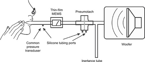
Conventional photolithography was used to pattern the serpentine MEMS structures on the surface of the 51 µm poly-imide film. The serpentine structure was oriented parallel to the film providing the best signal when the film is bent during airflow. Prior to metallization, the film substrate was heated at elevated temperatures (115°C) for a short time (5–10 minutes) to improve adhesion. An Angstrom Engineering’s Three Source Magnetron (Angstrom Engineering Inc., Kitchener, ON, Canada) was used to sputter 5 nm thick Cr and 400 nm thick Au layers on the film in high vacuum. Deposition times were several hours. When the sample was removed from the instrument, lift-off was performed using photolithography, acetone ultrasonic cleaning, followed by an isopropyl alcohol rinse. Fabricated sensors showed excellent adhesion of the metal layer to the substrate and passed the ASTM D3359-17 tape peel test. The MEMS films were also tested with dynamic stressing tests (Ω=4–200 Hz) using the woofer and MEMS sensor as shown in . Dynamic stressing tests were performed for at least 24 hours for monitoring the constancy of peak height during the experiments.
Figure 1 Test apparatus used for the dynamic oscillatory studies.
Thin-film probe construction
Prototype housings were constructed using balsa wood, since this is an easily worked material. Channels in a block of balsa (2˝×2˝×3˝) were machined using a router with straight bit shapes. The channel was sanded to remove stray filaments of wood on the side walls. Cyanoacrylate was used to seal the surfaces in the air chamber affording (after light sanding) smooth surfaces. Temporary paper stock spacers were used to position the sensor in the channel to ensure a tight fit with free movement after construction. Two separate pieces were placed on the top of the channel to firmly attach the sensor at the base. End caps were constructed from balsa and plywood using a ¾˝ Foster bit to allow ¾˝ airflow tubing to be attached. Cyanoacrylate glues of varying viscosities were used to seal the housing during the construction process. The finished structure was a rectangular box (2˝×2˝×4˝) with the channel running along the long axis (). A two wire 1/8” phone jack was used for electrical connection to pads on the thin-film MEMS structure. Resistance of the thin-film sensor was measured with an external Wheatstone bridge coupled with a Texas Instrument TI INA122PA operational amplifier (Texas Instruments Inc., Dallas, TX, USA).
Pneumotach, pressure sensors, and resistance standards
The pneumotach, a 4700 Series Hans Rudolph 0-160 LPM (Hans Rudolph Inc., Shawnee, KS, USA), was coupled with an Alpha Instruments Differential Pressure Model: 164W0001BC2YAA sensor (Servoflo Corporation, Lexington, MA, USA) using silicone tubing connected to the two pneumotach ports. The pressure sensor was connected to a second Alpha Instrument Differential Pressure Sensor connected singly to the instrument assembly with a silicone tube; the second port of the pressure sensor was vented to the atmosphere. The thin-film MEMS sensor was placed in series with the pneumotach. This study used an experimental configuration with both sensors in series (). For the steady state experiments, no load was present, or Hans Rudolph Flow Resistance Standards, linear type, available in standard ranges of 5, 20, 50, 200, 500, and 1000 cm H2O s/L, were employed.
The MATLAB software code (MathWorks, Natick, MA, USA) for the recursive least squares (RLS) algorithm was based on the algorithm developed by Jensen et alCitation13 The MATLAB Butterworth function (four pole) was used for the high pass filter with a cutoff frequency of 4 Hz. The forgetting factor for this calculation was set at 0.78, which, at 40 data points/second, sets the time constant to 0.1 seconds.Citation14
Short-time Fourier transform (STFT)
STFT scans were accomplished with Sigview software using the microphone channel of a computer as the input from either the pneumotach or thin-film MEMS sensors. Sigview is a real-time signal analysis software package available from SignalLab that uses the sound card to monitor the output from the operational amplifiers (SignalLab e.K., Pforzheim, Germany). Frequency scans, using the sub-woofer speaker as the sound source, were made starting at 2 Hz and scanning to 250 Hz in 30 seconds, followed by multiple Fourier analyses over short time intervals compared to the frequency scan. The relative intensity of the impedance, Z, is plotted on the z-axis and the frequency and time are plotted in the x–y plane.
Computational
A single ADC (analog-to-digital converter DI-1100; DATAQ Instruments Inc., Akron, OH, USA) simultaneously collected the data into [FPneumotachFThin-FilmPPressure] sets where F represents airflow and P represents pressure. Since the pressure data are common to both the flow sensors, the data are separated into two components: 1) pneumotach and 2) thin-film MEMS. A digital high-pass filter (four-pole Butterworth) was used to remove unwanted effects from tidal breathing and heart rate for the subjects at rest.
We assumed a linear model to the systems and apply RLS methodologyCitation13–Citation17 to obtain a phase space for the dynamical system (8 Hz) under study. RLS is a fast recursive algorithm, first introduced by Avanzolini et al,Citation14 that examines data in the past and computes updated parameter estimates as new data arrive, allowing almost real-time calculations of Z. Each flow sensor required its own phase correction factor, θ, applied as a phase shift to the complex Z data.
Results
Steady state experiments
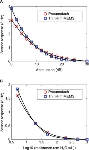
Two steady state studies were conducted to test the thin-film probe response vs that of the commercial pneumotach. The basic setup () was used, except that the subject was replaced with either no load, or a series of known airflow resistors. The oscillatory responses for both the pneumotach and thin-film sensors are plotted against the attenuation (dB) of the 8 Hz signal sent to the speaker and as a function of the standard Hans Rudolph airflow resistors (). Both the sensors gave smooth and nearly identical responses. In both the experiments, the thin-film sensor showed a higher response at high flow conditions; at lower flow, the pneumotach showed a slightly higher response. Both the sensors were demonstrated to cover the frequency ranges of interest.
Figure 2 Steady state responses comparing the thin-film sensor with a pneumotach.
Abbreviation: Log10, log 10 of the airflow resistor.
Human feasibility studies: dynamic studies
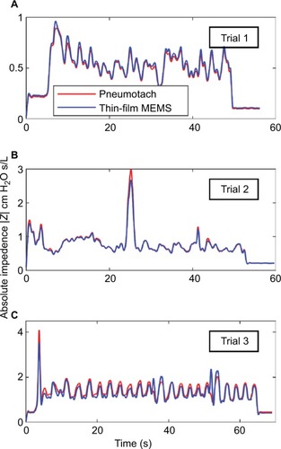
Data were collected at the Department of Biomedical Engineering Pulmonary testing lab at Boston University (using the apparatus shown in ). Three dynamic human test trials were successfully made with slightly different configurations, and the calculated absolute impedances, |Z|, for the two sensors compared to a common pressure sensor are presented in . The absolute values for the impedances for both the sensors matched almost exactly and indicated that phase corrections were needed to correlate airway resistance values.
Figure 3 Absolute impedances (Z) for three 8 Hz FOT trials using human subjects with the thin-film and pneumotach in series.
Abbreviations: FOT, forced oscillation technique; MEMS, micro-electromechanical system.
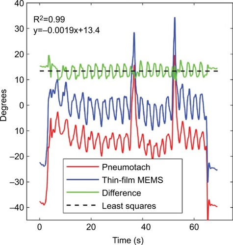
Using Trial 3 as an example, the phase corrections needed to correct the impedances for both sensors are presented in . The pneumotach and thin-film MEMS show essentially the same phase behavior, with the exception that an offset phase correction was needed for both sensors to achieve reasonable resistance and reactance components. From this plot, we determined that θ was 38° and 23°, respectively. The mean phase shift difference between the thin-film MEMS sensor and the pneumotach observed in this run was 13°. Minor variances were observed in the difference curve. At the beginning of the trials, the phase should be set to zero since no load is present. The same value of θ was used for all three trials.
Figure 4 Computed raw phases for the pneumotach and thin-film MEMS sensor during Trial 3.
Abbreviation: MEMS, micro-electro-mechanical system.
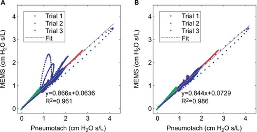
The corrected airway resistances for both sensors during Trial 3 after phase correction indicate essentially similar responses (). This trial showed tidal breathing of the subject with two deep inhalations (DI) at ~38 and ~52 seconds. Prior to the two DI events, we observed a sharp rise in resistance consistent with glottic closure. Reflex glottic closure is a reflex produced by the stimulation of the superior laryngeal nerve. Precise glottic closure execution is basic to successful sphincteric protection, with a rapid elimination of the airflow from the lower airways. Glottic closure is a common technical problem in spirometry as well as oscillatory methods.Citation18,Citation19 Bhatawadekar et alCitation20,Citation21 have discussed the exclusion of non-pertinent events such as swallowing, glottic closure, and coughing from pulmonary measurements. During Trial 3, the subject made eleven tidal breaths (TBs), a DI #1 (38 seconds), followed by five TBs, a DI #2 (52 seconds), four TBs, and then the subject was disconnected from the apparatus. Two glottic closures were observed during the DI procedures. A comparison of the airflow resistance between the two sensors for all three trials indicates good correlations between the two airflow sensors (), and if we remove the glottic events in Trial 3 (), improved correlations are obtained.
Figure 5 Comparison of the airway resistance (R) during Trial 3 for the pneumotach and thin-film sensor connected in series.
Abbreviations: DI, deep inhalation; MEMS, micro-electro-mechanical system.
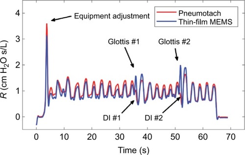
Figure 6 Cross correlation of airway resistance (R) between the pneumotach and the thin-film MEMS sensor during Trial 3.
Abbreviation: MEMS, micro-electro-mechanical system.
Frequency response comparison
There is a considerable interest in extending the range of FOT to higher frequencies.Citation15,Citation22–Citation26 In the range of ~40–250 Hz, anti-resonances in the lung are prominent, and changes in the location have been correlated with spirometry. Frey et alCitation27 have demonstrated the efficacy of the respiratory impedance at high frequencies in infants. A higher frequency response for the airflow sensor is advantageous for higher oscillatory studies. In an early study by Finucane et al, Citation7 both screen and capillary tube pneumotachs were studied for steady state and periodic flows. Renzi et alCitation28 have reported that pneumotachs have a frequency response up to ~20 Hz, which can be extended to 100 Hz using digital compensation.
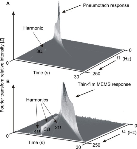
We have measured frequency responses of the pneumotach used in this study and several thin-film probes with different geometries by sweeping the frequency delivered by the speaker from 2 to 250 Hz over a time of 30 seconds. Using STFT techniques, where the time is subdivided into shorter segments of equal length followed by a digital Fourier transform, the absolute intensity vs time for the pneumotach and a thin-film MEMS probe demonstrates dynamic testing (). An ideal sensor should show a sharp wall of constant height along the diagonal. The Hans Rudolph Series 4700 pneumotach used in this study was observed in our setup to peak at ~45 Hz, followed by a rapid drop-off. In contrast, the thin-film MEMS probe (lower) shows a nearly constant response up to ~200 Hz. We have observed that the frequency response for thin-film MEMS sensors is very dependent on probe and sensor geometry. These observations suggest that thin-film MEMS technology offers a new platform for probing FOT frequency response over a broader frequency range that can include measurement of pulmonary anti-resonance conditions. The thin-film probe may also show promise in capturing low frequency lung soundsCitation29 in the range of 0–200 Hz, as well as serving as an airflow sensor in spirometry and FOT.
Figure 7 Short-time Fourier transform spectra of the two types of probes used in this study.
Abbreviation: MEMS, micro-electro-mechanical system.
Discussion
In this analysis, no artificial correction factors were employed for calibration purposes. The two data streams from the pneumotach and thin-film MEMS sensors were normalized by their root mean squares values, followed by identical RLS analysis. We used a separate independent calibration for the pneumotach to set the calibration for both MEMS and pneumotach flow sensors.
We have demonstrated quantitatively that thin-film MEMS sensors can be used to track airway resistance and provide data that “fit like a glove” with pneumotach data. Highly flexible thin-film and fiber technologies offer promise for a new method to measure low levels of oscillatory flow with increased sensitivity and functionality. For portable equipment used in the field, flexible and compliant electronicsCitation30,Citation31 may be a simple solution to one of the problems facing the pneumotach, namely clogging of the screen or tubes with dirt or mucus, which seriously compromises accuracy and reproducibility.Citation32 The pneumotach is also typically equipped with a heater to keep condensation from forming on the pneumotach screen. An additional benefit of the thin-film MEMS structure is that heat is generated during operation through resistive heating (~0.1 W), preventing moisture condensation during subject testing.
These data leave several unanswered questions, particularly regarding the limits for increasing the sensitivity of both the sensors and thereby avoiding the necessity of heavy large speakers and an accompanying power source. Thin-film technology is amenable to modifications in size, substrate flexibility, and the addition of sophisticated electronics. We note that the filtered raw data for Trial 3 show that the thin-film MEMS oscillatory response increased abruptly at 38 and 52 seconds, in contrast to the pneumotach, suggesting that the thin flow sensors may be more responsive to rapid changes in air flow. Our frequency sweep studies also indicate a wider frequency response for the MEMS sensor compared to a pneumotach.
Conclusion
These data support the hypothesis that thin-film MEMS sensors based on polyimide substrates can be successfully used to replace the pneumotach in the FOT instrument. Other transducersCitation33 useful for pulmonary airflow include hot-wire anemometers, turbines, and ultrasonic time-of-flight. Ultrasonic time-of-flight has been used to obtain preliminary oscillatory data suitable for FOT analyses.Citation34,Citation35 To our knowledge, this study represents the first description using a thin-film MEMS device for FOT. We are continuing to develop home-based FOT devices that will be useful for patients with labile obstructive lung disease who are at high risk of hospitalization and emergency room visits. Our vision is to develop portable multi-parameter monitoring devices that can send data to a central server where they are stored against the patients’ medical records. A portable, easy-to-use, home-based FOT instrument will reduce costly hospital and emergency visits for obstructive pulmonary constriction.Citation36
Author contributions
CEF, REC, SLM, BDG, and KRL participated in the conception and design of research. XKX, BPH, KRL, SLM, and CEF performed experiments, and XKX prepared sensors and probes. All authors contributed to data analysis, critically revising the paper, and agree to be accountable for this work.
Acknowledgments
Sensors were fabricated at the Princeton Institute for the Science and Technology of Materials, an interdisciplinary research center at Princeton University. Calibration work was performed at Boston University’s Respiratory and Physiological Systems Identification Laboratory. Feather Sensors, LLC (Millville, NJ, USA) is the manufacturer of the MEMS sensor system that was used in this study. We thank Larry Ericksen and Patrick Lichter for their insights and comments on the preparation of this manuscript.
This work was supported by the National Science Foundation under SBIR Grant 1248714.
Disclosure
CEF and REC are the owners of Feather Sensors, LLC, and XKX and SLM were employees of Feather Sensors, LLC at the time of this work. BPH was a graduate student of KRL (Boston University) during this work. The authors report no other conflicts of interest in this work.
References
- DuboisABBrodyAWLewisDHBurgessBFOscillation mechanics of lungs and chest in manJ Appl Physiol19568658759413331841
- BatesJHLung Mechanics: An Inverse Modeling ApproachCambridgeCambridge University Press2009
- LutchenKRSukiBUnderstanding pulmonary mechanics using the forced oscillations techniqueKhooMCKBioengineering Approaches to Pulmonary Physiology and MedicineBoston, MASpringer1996227253
- StrömbergNOGrönkvistMJImproved accuracy and extended flow range for a Fleisch pneumotachographMed Biol Eng Comput199937445646010696702
- KreitJWSciurbaFCThe accuracy of pneumotachograph measurements during mechanical ventilationAm J Respir Crit Care Med19961544 Pt 19139178887585
- GregoryGAKittermanJAPneumotachograph for use with infants during spontaneous or assisted ventilationJ Appl Physiol19713157667675117194
- FinucaneKEEganBADawsonSVLinearity and frequency response of pneumotachographsJ Appl Physiol19723211211265007001
- ForbesCCoifmanRMonfreSAssessment of a low cost thin film bidirectional airflow probe for pulmonary applicationsBiochem Physiol2012116
- SuoZMechanics of stretchable electronics and soft machinesMRS Bull20123703218225
- LarsenGLMorganWHeldtGPImpulse oscillometry versus spirometry in a long-term study of controller therapy for pediatric asthmaJ Allergy Clin Immunol20091234861867.e119070356
- NavajasDFarréRForced oscillation assessment of respiratory mechanics in ventilated patientsCrit Care20015131811178220
- RegelmannWESchechterMSWagenerJSPulmonary exacer-bations in cystic fibrosis: young children with characteristic signs and symptomsPediatr Pulmonol201348764965722949088
- JensenAAtilehHSukiBIngenitoEPLutchenKRSelected contribution: airway caliber in healthy and asthmatic subjects: effects of bronchial challenge and deep inspirationsJ Appl Physiol200191150651511408470
- AvanzoliniGBarbiniPCappelloACeveniniGChiariLA new approach for tracking respiratory mechanical parameters in real-timeAnn Biomed Eng19972511541639124729
- BatesJHLauzonAMDechmanGSMaksymGNSchuesslerTFTemporal dynamics of pulmonary response to intravenous histamine in dogs: effects of dose and lung volumeJ Appl Physiol19947626166268175571
- AvanzoliniGBarbiniPCappelloACeveniniGReal-time tracking of parameters of lung mechanics: emphasis on algorithm tuningJ Biomed Eng19901264894952266745
- LutchenKRJensenAAtilehHAirway constriction pattern is a central component of asthma severity: the role of deep inspirationsAm J Respir Crit Care Med2001164220721511463589
- DellacàRLSantusPAlivertiADetection of expiratory flow limitation in COPD using the forced oscillation techniqueEur Respir J200423223224014979497
- PeslinRYingYGallinaCDuvivierCWithin-breath variations of forced oscillation resistance in healthy subjectsEur Respir J19925186921577156
- BhatawadekarSALearyDChenYA study of artifacts and their removal during forced oscillation of the respiratory systemAnn Biomed Eng2013415990100223297001
- LearyDBhatawadekarSAParragaGMaksymGNModeling stochastic and spatial heterogeneity in a human airway tree to determine variation in respiratory system resistanceJ Appl Physiol2012112116717521998266
- ChalkerRBCelliBRHabibRHJacksonACRespiratory input impedance from 4 to 256 Hz in normals and chronic airflow obstruction: comparisons and correlations with spirometryAm Rev Respir Dis199214635705761519830
- DorkinHLLutchenKRJacksonACHuman respiratory input impedance from 4 to 200 Hz: physiological and modeling considerationsJ Appl Physiol19886428238313372439
- FarréRPeslinROostveenESukiBDuvivierCNavajasDHuman respiratory impedance from 8 to 256 Hz corrected for upper airway shuntJ Appl Physiol1989675197319812600029
- HabibRHSukiBBatesJHJacksonACSerial distribution of airway mechanical properties in dogs: effects of histamineJ Appl Physiol19947725545668002500
- JacksonACGiurdanellaCADorkinHLDensity dependence of respiratory system impedances between 5 and 320 Hz in humansJ Appl Physiol1989676232323302606839
- FreyUSilvermanMKraemerRJacksonACHigh-frequency respiratory impedance measured by forced-oscillation technique in infantsAm J Respir Crit Care Med199815823633709700108
- RenziPEGiurdanellaCAJacksonACImproved frequency response of pneumotachometers by digital compensationJ Appl Physiol19906813823862312481
- GavrielyNNissanMCugellDWRubinAHRespiratory health screening using pulmonary function tests and lung sound analysisEur Respir J19947135428143829
- TsayCLacourSPWagnerSLiTSuoZHow stretchable can we make thin metal films?Poster presented at: Materials Research Society Symposium ProceedingsMarch 28–April 1 2005San Francisco, CA
- LacourSPChanDWagnerSLiTSuoZMechanisms of reversible stretchability of thin metal films on elastomeric substratesAppl Phys Lett20068820204103
- SchiblerAHallGLBusingerFMeasurement of lung volume and ventilation distribution with an ultrasonic flow meter in healthy infantsEur Respir J200220491291812412683
- GravensteinJSJaffeMBGravensteinNPaulusDACapnographyCambridgeCambridge University Press2011
- AraujoGAJuniorRTFreireRUltrasonic anemometer for the measurement of respiratory flow in the forced oscillation techniquePoster presented at: IEEE International Workshop on Medical Measurement and Applications, 2007 (MEMEA’07)May 4–5, 2007Warsaw, Poland
- CaoJSabharwalAPortable forced oscillation device for point-of-care pulmonary function testingConf Proc IEEE Eng Med Biol Soc201620162282228628268783
- CoifmanREDynamic approach to asthmaJ Asthma198320145526853428