
Abstract
The miniscrew-assisted rapid palatal expansion approach has given new opportunities for the treatment of maxilla transverse deficiency by providing an alternative to the surgical approach for adult patients. However, the presence of a thin palatal bone can compromise the success of such approach. Recently, the digital planning of the miniscrew-assisted appliances has offered unique advantages in terms of safety and accuracy of the overall process. The aim of this study is to describe the digital planning and MSE fabrication with cad-cam technology using 6 mini-screws in cases with a palatal bone thickness of less than 2.5 mm.
Introduction
Maxillary transverse deficiency is a common situation in orthodontics.Citation1 Prior to the pubertal spurt, the use of a tooth-borne maxillary expander produces good skeletal resultsCitation2 despite the dentoalveolar side effects.Citation3–Citation5 However, in adult patients, there is a higher resistance of the matured midpalatal and circum-maxillary sutures.Citation6 In such cases, the surgically assisted rapid palatal expansion (SARPE) was the only treatment option.Citation7
In the last years, the use of miniscrew-assisted rapid palatal expansion (MARPE) has given new opportunities for the treatment of maxillary transverse deficiency in adult patients. Numerous MARPE appliances have been proposed.Citation8–Citation12 One of them, the maxillary skeletal expander (MSE) (BioMaterials Korea, Seoul, Korea),Citation13 uses four mini-screws located at the posterior part of the palate for a favorable force vector for maxilla expansion. Furthermore, the bicortical engagement of its mini-screws aims to generate a greater skeletal effect and a more parallel pattern of expansion.Citation14 Recently, the digital planning of MARPE has offered unique advantages in terms of safety of implant placement.Citation15–Citation19 However, treatment of patients with a thin posterior palatal bone remains challenging.
Methods
A written informed consent to participate in the study and to publish the case details and images was obtained by the patient for clinical case 2, and by the patient’s legal guardian for clinical case 1. Institutional approval to publish the case details was not needed.
The digital planning and cad-cam fabrication of MSE with 6 mini-screws for cases with a palatal bone thickness of less than 2.5 mm is described through two clinical cases. The process involves the selective laser melting (SLM) technology to manufacture the adjunct parts of the appliance and the laser welding of the adjunct parts to the prefabricated MSE.
Clinical Case 1
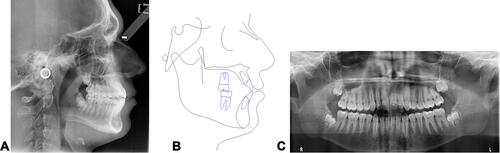
A 15 years and 4 months old patient presented with reduced incisor display during smile ( and ). Intra-oral examination revealed a slight Class III molar relationship (1.5 mm), moderate crowding in the upper dental arch, minimal Overjet and Overbite, a crossbite from upper left lateral incisor to first molar, and the presence of macroglossia. Mandibular midline was deviated to the left by 1.5 mm. The cephalometric analysis () showed a Class I skeletal relationship with Class III tendency (Wits Appraisal of −1.3 mm and ANB angle of 0.8°) with brachyfacial skeletal pattern, and proclination of upper and lower incisors. The aim of the treatment was to resolve the lateral cross bite, advance the maxilla forward and align the dental arches. The MSE appliance (BioMaterials Korea, Seoul, Korea) was utilized for the lateral crossbite correction and maxilla advancement. The original MSE appliance comes with a main body with 4 slots for miniscrews, an expansion jack screw, and 4 supporting arms that connect the MSE body to the molar bands.Citation13,Citation14
Table 1 Cephalometric Analysis (Clinical Case 1)
Figure 1 Clinical case 1: initial pictures of face and intraoral images.
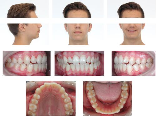
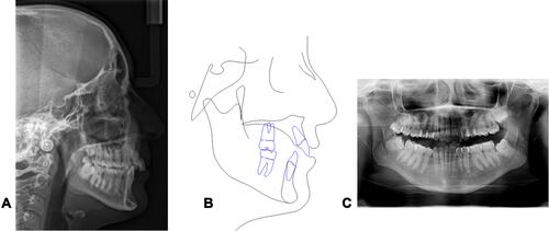
Figure 2 Clinical case 1: initial lateral head film (A), cephalometric tracing (B) and panorex (C).
A cone-beam computed tomography (CBCT) exam of the maxilla was obtained with the Giano HR scanner (NewTom, Verona, Italy) with a field of view (FOV) of 7×6 cm. An impression of dental arches was generated with alginate material; the stone models were poured and then scanned with the Aaton scanner (88Dent, Pero, Italy) to obtain a digital model. Patient CBCT and virtual model of dental arches were merged with Real Guide software (3Diemme, Figino Serenza, Italy).
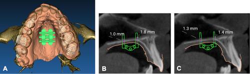
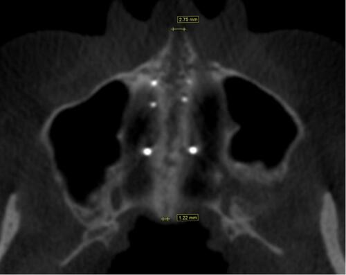
A virtual model of MSE appliance with 4 miniscrews was imported in Real Guide software, as described in a previous publicationCitation19 and the palatal bone thickness was assessed with the software ruler (). The bone thickness at the miniscrews insertion sites was less than 2 mm. For this reason, two additional miniscrews were planned to be incorporated with the MSE appliance for additional anchorage support.
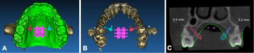
Figure 3 Positioning of MSE virtual model (A) on the integrated model of patient CBCT and digital model of maxillary dental arch. (B) Occlusal view. (C) Measurement of bone thickness at the level of left miniscrews. (D) Measurement of bone thickness at the level of right miniscrews. (A) is reproduced with permission from Dove Medical Press. Cantarella D, Savio G, Grigolato L, et al. A new methodology for the digital planning of micro-implant-supported maxillary skeletal expansion. Med Devices Evid Res. 2020;13:93–106.Citation19
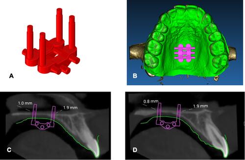
The virtual model of two bushings with miniscrews inside (),Citation20 was imported in Real Guide software. Miniscrews were positioned in the patient CBCT where the bone thickness was greater, on the palatal side of alveolar processes, between second premolars and first molars ().
Figure 4 Bushing and miniscrew utilized for lateral positioning between second premolar and first molar. (A) Virtual model. (B) Physical bushing produced with selective laser melting technology and conventional prefabricated miniscrew. (C) 0.010 steel ligature tie between head of miniscrew and bushing pin. Adapted with permission from Cantarella D, Quinzi V, Karanxha L, Zanata P, Savio G, Del Fabbro M. Digital workflow for 3D design and additive manufacturing of a new miniscrew-supported appliance for orthodontic tooth movement. Appl Sci. 2021;11.Citation20
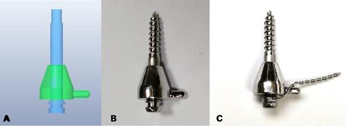
Figure 5 Positioning of virtual model of additional lateral bushings and miniscrews on the patient integrated model. (A) Occlusal view. (B) View from top, after isolating dental crowns and roots. (C) Coronal view with measurement of bone thickness at the level of additional lateral miniscrews.
The auxiliary structure was designed with Dental Wings software (Dental Wings, Montreal, QC, Canada). The connecting arms bridged from the bushings to the MSE body and to the molar bands ().
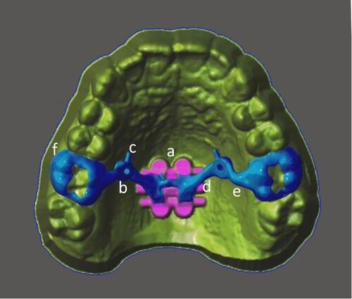
Figure 6 Virtual model of cad-cam structure. (a) MSE body. (b) Bushing for lateral miniscrew. (c) Pin for steel ligature tie. (d) Connecting arm between bushing and MSE body. (e) Connecting arm between bushing and molar band. (f) Cad-cam molar band.
The structure was then manufactured with selective laser melting (SLM) technology with Mysint 100 machine (Sisma, Piovene Rocchette, Italy) and Mediloy S-Co Cobalt-Chromium alloy (Bego, Bremen, Germany). Subsequently, the cad-cam structure was polished and laser welded to the MSE body, followed by the removal of the preformed arms of MSE.
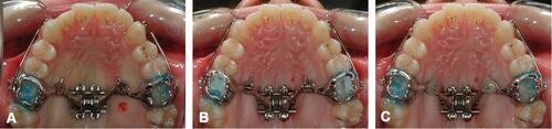
The appliance was cemented in the oral cavity and 6 miniscrews were inserted in the 4 MSE body slots and the 2 lateral bushings of the cad-cam structure. All miniscrews presented a diameter of 1.8 mm. MSE body miniscrews had a length of 11 mm, while miniscrews in the 2 lateral bushings had a length of 13 mm. For the 2 lateral miniscrews, a 0.010 steel ligature was tied from the miniscrew head to a pin present on the bushing (), and then covered with Flow composite material ().
Figure 7 Positioning of MSE appliance in the oral cavity. (A) After cementation of molar bands. (B) After positioning of 6 miniscrews and tie with 0.010 steel ligature between head of lateral miniscrew and bushing pin. (C) After positioning of composite flow on top of lateral miniscrew heads and bushings.
Two activations per day (0.267 mm expansion) were done with a total activation of 7 mm (). The post-expansion CBCT showed a split of 5.02 mm at the anterior nasal spine (ANS) and 4.16 mm at the posterior nasal spine (PNS). Lateral miniscrews were away from the roots of first molars and second premolars, as shown in a coronal section of the CBCT (). The patient promoted a maxillary protraction with elastics (3/8”, 16 ounces) from the facemask to the MSE hooks at night-time and with Class III intraoral elastics (3/16”, 6 ounces) from the modified lower lingual arch to the maxillary molar bands at day-time (), until achievement of slight Class II molar and canine relationship (). Finishing and detailing of dental occlusion will then be performed with fixed appliance.
Figure 8 Patient records after maxillary expansion. (A) Intraoral occlusal picture. (B) Intraoral frontal picture. (C) CBCT axial palatal section. (D) 3D rendering of maxilla. (E) CBCT coronal section through the 2 additional lateral miniscrews.
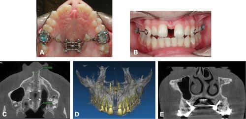
Figure 9 Maxillary protraction with facemask at night-time (A) and with intraoral elastics from a modified lingual arch to maxillary molar bands (B–F) during day-time.
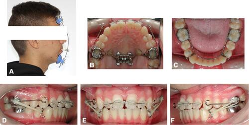
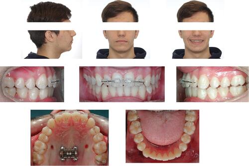
Figure 10 Facial and intraoral pictures after maxillary protraction.
Clinical Case 2
A 33-year-10-month-old female patient presented with the chief complaint of a midline shift in her upper dental arch ( and ). Intra-oral examination revealed missing teeth (number 2.4, 3.3, and 4.4), and maxillary midline deviation of 4 mm to the left. She had a Class II subdivision on the right side, increased overjet and overbite as well as right posterior crossbite. The cephalometric analysis () showed a mesocephalic severe Class II skeletal pattern due to a retruded mandible (Wits Appraisal of 2.8 mm), with proclination of upper incisors and retroclination of lower incisors.
Table 2 Cephalometric Analysis (Clinical Case 2)
Figure 11 Clinical case 2: initial pictures of face and intraoral images.
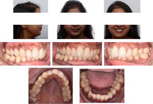
Figure 12 Clinical case 2: initial lateral head film (A), cephalometric tracing (B) and panorex (C).
The main treatment objective was to resolve the maxillary transverse deficiency followed by proper teeth alignment and midline discrepancy correction. Maxillary expansion with MSE was chosen for the treatment of the crossbite. The extraction of tooth # 1.4 was also included in the treatment plan to allow the correction of the maxillary midline shift.
A CBCT exam was taken with Kavo OP 3D scanner (Kavo Dental GmbH, Biberach, Germany) with a large field of view (FOV) of 10×16 cm. Intraoral scans were taken with an iTero Element 2 scanner (Align Technology, San Jose, California, USA) and exported through the myCadent-Database as STL-File. The CBCT and the STL files were merged to create an integrated model, and the virtual model of MSE was imported and positioned. The bone thicknesses at the miniscrews insertion sites were measured and found to be less than 2 mm (); hence, incorporating 2 additional miniscrews was planned.
Figure 13 Positioning of MSE virtual model on the integrated model of patient CBCT and digital model of maxillary dental arch. (A) Occlusal view. (B) Measurement of bone thickness at the level of left miniscrews. (C) Measurement of bone thickness at the level of right miniscrews.
A virtual model of bushing with miniscrew inside was generated with Rhinoceros software (). It was imported in the patient’s integrated model, and positioned anteriorly to the MSE body where bone thickness was higher (). The bushings were produced with selective laser melting technique, placed in a positioning guide with MSE appliance, and laser welded to the MSE body.
Figure 14 Virtual model of bushing and miniscrew utilized for anterior positioning. (A) Lateral view. (B) Anterior view.
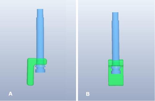
Figure 15 Positioning of virtual model of additional anterior bushings and miniscrews on the patient integrated model. (A) Occlusal view. (B) ¾ view. (C) Sagittal section, measurement of bone thickness at the level of additional anterior right miniscrew. (D) Sagittal section, measurement of bone thickness at the level of additional anterior left miniscrew. (E) Finalized MSE appliance.
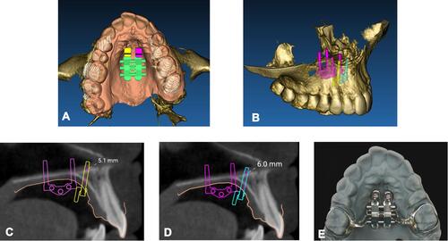
The appliance () was cemented intraorally, and six miniscrews were inserted. Miniscrews had a diameter of 1.8 mm; the MSE body miniscrews had a length of 11 mm, while the additional anterior miniscrews were 13 mm long. Then, six micro-osteoperforations were performed longitudinally along the midpalatal suture, from the molar to the canine area. Two activations per day were done until a diastema appeared (). A follow-up CBCT scan was taken after the expansion was maximized (). In order to completely resolve the crossbite, a second MSE was planned.
Figure 16 Facial and intraoral pictures after maxillary expansion.
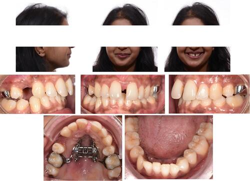
Figure 17 Axial palatal section on patient CBCT after maxillary expansion.
Discussion
MARPE protocol offers an alternative to SARPE for skeletally mature patients.Citation21,Citation22 MSE is a well-documented type of MARPE that exploits the concept of producing a posterior force vector by the posterior positioning of jackscrew and a more stable anchorage by the bicortical engagement of its four mini-screws, which produces a parallel pattern of skeletal expansion in the horizontal plane.Citation23–Citation27
Traditionally, MSE appliances are manufactured on stone models. In a recent publication, digital planning of MSE based on a patient’s CBCT image has been proposed.Citation19 In brief, after placing a digital MSE in a preferred position within a 3D image generated from the CBCT data, a 3D-printed positioning guide is produced. The guide is utilized by the lab technician for ideal MSE position prior to bending and welding of the MSE arms to molar bands. Such a workflow can improve safety and accuracy of the treatment. The 3D digital plan defines the ideal position of MSE relative to the midface skeletal structures and the insertion site of mini-screws, which optimizes the biomechanics of midface expansion, maximizes bone availability for miniscrews and reduces any risk of adverse effects on relevant nearby structures.
Digital planning of MSE also allows one to choose the appropriate length of miniscrews so that they penetrate the cortical bone layers of the oral cavity vault and nasal floor. The main stability of the miniscrew is generated by its engagement with the cortical bone. The palatal bone is relatively thin, and a firm penetration through both cortical layers (bicortical anchorage) is particularly critical for the stability of miniscrews during the palatal expansion with orthopedic force, causing less tipping of the implants and minimizing the internal strain placed at the neck of the micro-implants.Citation13,Citation14,Citation26 Miniscrews typically penetrate 1 mm into the nasal cavity, and no adverse effects related to nasal penetration have been reported since its inception. The MSE was first developed in 2004, and its application has been widely adopted internationally. The nasal penetration appears to be safe and has become a commonly practiced protocol.
Utilization of this digital technology for MSE treatments revealed that some patients have palatal bone thickness of less than 2.5 mm. Although there is not any scientific evidence indicating the required bone thickness of anchor bone necessary to withstand the required expansion force based on individual skeletal variations, it is conceivable that bone-borne expansion with a thin palatal bone can be challenging in terms of the implant stability during the expansion, which can compromise the overall treatment outcome.
To avoid the miniscrew instability in such cases, we propose a CAD/CAM workflow of an MSE fabrication with two additional mini-screws. For the initial digital planning of MSE placement, the same methodology as described by Cantarella et al was used.Citation19 For the two additional mini-screws, a 3D design of a bushing with a cylinder inside was used. The bushing represents the slot for the miniscrew insertion, and the cylinder represents the mini-screw itselfCitation20 ( and ). The bushings can be either incorporated in a cad-cam structure () that is later laser welded to MSE body or directly welded to MSE body ().
The two additional mini-screws can be placed laterally as in case 1, at the palatal side of the alveolar bone between the second premolar and the first molar. This way the orthopedic effect of expansion is maximized given that all six mini-screws are placed close to the bi-zygomatic line, where the highest resistance is experienced during expansion (). However, this location requires a careful digital planning in order to avoid any contact with the roots of the adjacent teeth ( and ). In the presented case 1, after the successful split of the midpalatal suture, the miniscrews were distant from the roots (), showing the safety of the procedure. However, this location may be contraindicated when the inter-radicular space is small. Lastly, the lateral location makes the clinical procedure slightly more complex, as the clinician must steel tie the mini-screw head with the pin of the bushing.
Figure 18 Variation of distance from additional miniscrews to bizygomatic line (BZL), depending on miniscrews location. Distance (red arrows) is much shorter for additional miniscrews placed laterally, between second premolar and first molar (A), than for miniscrews placed anteriorly to MSE body (distance represented by blue arrows) as shown in (B).
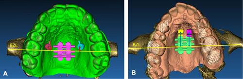
As an alternative, the two additional mini-screws can be placed anteriorly as in case 2, where the available bone is generally thicker. The clinical procedure in this case is simpler. Another advantage of this alternative is that the original arms of MSE appliance, which are made with a ductile material, can be maintained since the bushings are not soldered/welded to the arms as in the Case 1. The preservation of the soft arms reduces the load on molars during appliance activation. However, the two additional mini-screws are placed farther from the center of resistance against expansion (), which increases the possibility of a non-parallel, v-shaped, pattern of maxillary expansion. In fact, the ratio between the PNS and ANS splits in case 2 was 44%, much lower than the 83% ratio of case 1.
In both cases, following the digital planning, the selective laser melting technique was used for the fabrication of these adjunct parts of the appliance. During intraoral delivery, the appliance was cemented first, serving as a surgical guide for the mini-screws insertion.
These case studies explored the possibilities of MSE appliance modification for selective cases with poor palatal anchor bone.
Summary and Conclusions
In the present study, a digital workflow is described for planning and fabrication of the modified MSE when the palatal bone is thinner than 2.5 mm. Two additional mini-screws were added to the original MSE appliance. Two different locations for the additional mini-screws are described: lateral and anterior locations. By taking the advantages of digital technology, the appliance design can be customized for each specific case.
Disclosure
Massimo Del Fabbro and Won Moon are co-last authors for this study. The authors report no conflicts of interest in this work.
References
- McNamara JA. Maxillary transverse deficiency. Am J Orthod Dentofacial Orthop. 2000;117(5):567–570. doi:10.1016/S0889-5406(00)70202-2
- Hass AJ. The treatment of maxillary deficiency by opening the midpalatal suture. Angle Orthod. 1965;35(200):17.
- Rungcharassaeng K, Caruso JM, Kan JYK, Kim J, Taylor G. Factors affecting buccal bone changes of maxillary posterior teeth after rapid maxillary expansion. Am J Orthod Dentofac Orthop. 2007;132(4):428.e1–428.e8.
- Baysal A, Uysal T, Veli I, Ozer T, Karadede I, Hekimoglu S. Evaluation of alveolar bone loss following rapid maxillary expansion using cone-beam computed tomography. Korean J Orthod. 2013;43(2):83–95.
- Kiliç N, Kiki A, Oktay H. A comparison of dentoalveolar inclination treated by two palatal expanders. Eur J Orthod. 2008;30(1):67–72.
- Melsen B. Palatal growth studied on human autopsy material. A histologic microradiographic study. Am J Orthod. 1975;68(1):42–54.
- Byloff FK, Mossaz CF. Skeletal and dental changes following surgically assisted rapid palatal expansion. Eur J Orthod. 2004;26(4):403–409.
- Wilmes B, Nienkemper M, Drescher D. Application and effectiveness of a mini-implant- and tooth-borne rapid palatal expansion device: the hybrid hyrax. World J Orthod. 2010;11(4):323–330.
- Vassar JW, Karydis A, Trojan T, Fisher J. Dentoskeletal effects of a temporary skeletal Anchorage device-supported rapid maxillary expansion appliance (TSADRME): a pilot study. Angle Orthod. 2016;86(2):241–249.
- Mosleh MI, Kaddah Ma, Abd Elsayed FA, Elsayed HS. Comparison of transverse changes during maxillary expansion with 4-point bone-borne and tooth-borne maxillary expanders. Am J Orthod Dentofac Orthop. 2015;148(4):599–607. doi:10.1016/j.ajodo.2015.04.040
- Lee KJ, Park YC, Park JY, Hwang WS. Miniscrew-assisted nonsurgical palatal expansion before orthognathic surgery for a patient with severe mandibular prognathism. Am J Orthod Dentofac Orthop. 2010;137(6):830–839. doi:10.1016/j.ajodo.2007.10.065.
- Maino BG, Paoletto E, Cremonini F, Liou E, Lombardo L. Tandem skeletal expander and MAPA protocol for palatal expansion in adults. J Clin Orthod. 2020;54(11):690–704.
- Carlson C, Sung J, McComb RW, MacHado AW, Moon W. Microimplant-assisted rapid palatal expansion appliance to orthopedically correct transverse maxillary deficiency in an adult. Am J Orthod Dentofac Orthop. 2016;149(5):716–728. doi:10.1016/j.ajodo.2015.04.043
- Cantarella D, Dominguez-Mompell R, Mallya SM, et al. Changes in the midpalatal and pterygopalatine sutures induced by micro-implant-supported skeletal expander, analyzed with a novel 3D method based on CBCT imaging. Prog Orthod. 2017;18:1.
- Vaid NR. Up in the air: orthodontic technology unplugged! APOS Trends Orthod. 2017;7:1–5.
- Graf S, Hansa I. Clinical guidelines to integrate temporary Anchorage devices for bone-borne orthodontic appliances in the digital workflow. APOS Trends Orthod. 2019;9:182–9.
- De Gabriele O, Dallatana G, Riva R, Vasuvdavan S, Wilmes B. The easy driver for placement of palatal mini-implants and a maxillary expander in a single appointment. J Clin Orthod. 2017;51(11):728–737.
- Maino BG, Paoletto E, Lombardo L, Siciliani G. A three-dimensional digital insertion guide for palatal miniscrew placement. J Clin Orthod. 2016;50(1):12–22.
- Cantarella D, Savio G, Grigolato L, et al. A new methodology for the digital planning of micro-implant-supported maxillary skeletal expansion. Med Devices Evid Res. 2020;13:93–106.
- Cantarella D, Quinzi V, Karanxha L, Zanata P, Savio G, Del Fabbro M. Digital workflow for 3d design and additive manufacturing of a new miniscrew-supported appliance for orthodontic tooth movement. Appl Sci. 2021;11:3.
- Choi SH, Shi KK, Cha JY, Park YC, Lee KJ. Nonsurgical miniscrew-assisted rapid maxillary expansion results in acceptable stability in young adults. Angle Orthod. 2016;86(5):713–720.
- Suzuki H, Moon W, Previdente LH, Suzuki SS, Garcez AS, Consolaro A. Miniscrew-assisted rapid palatal expander (MARPE): the quest for pure orthopedic movement. Dental Press J Orthod. 2016;21(4):17–23.
- Cantarella D, Dominguez-Mompell R, Moschik C, et al. Midfacial changes in the coronal plane induced by microimplant-supported skeletal expander, studied with cone-beam computed tomography images. Am J Orthod Dentofac Orthop. 2018;154(3):337–345. doi:10.1016/j.ajodo.2017.11.033
- Elkenawy I, Fijany L, Colak O, et al. An assessment of the magnitude, parallelism, and asymmetry of micro-implant-assisted rapid maxillary expansion in non-growing patients. Prog Orthod. 2020;21:1.
- Song KT, Park JH, Moon W, Chae JM, Kang KH. Three-dimensional changes of the zygomaticomaxillary complex after mini-implant assisted rapid maxillary expansion. Am J Orthod Dentofac Orthop. 2019;156(5):653–662. doi:10.1016/j.ajodo.2018.11.019
- Lee RJ, Moon W, Hong C. Effects of monocortical and bicortical mini-implant Anchorage on bone-borne palatal expansion using finite element analysis. Am J Orthod Dentofac Orthop. 2017;151(5):887–897. doi:10.1016/j.ajodo.2016.10.025
- Li N, Sun W, Li Q, Dong W, Martin D, Guo J. Skeletal effects of monocortical and bicortical mini-implant Anchorage on maxillary expansion using cone-beam computed tomography in young adults. Am J Orthod Dentofac Orthop. 2020;157(5):651–661.