
 ?Mathematical formulae have been encoded as MathML and are displayed in this HTML version using MathJax in order to improve their display. Uncheck the box to turn MathJax off. This feature requires Javascript. Click on a formula to zoom.
Abstract
To control and drive a robotic capsule accurately from outside a patient’s body, we present a schema in which the capsule enclosing the imaging device, circuits, batteries, etc is looped by a permanent magnet ring that acts as an actuator. A cuboidal permanent magnet situated outside the patient’s body attracts or pushes the magnet ring from different directions to make the capsule move or rotate. A mathematic model of attractive or repulsive force that the cuboidal magnet exerts on the magnet ring is presented for accurate calculation of force. The experiments showed that the measuring force was in agreement with the theoretical one, and the relations between the dimensions of the cuboidal magnet and force are useful to produce a cuboidal magnet with optimal shape to get appropriate force.
Introduction
Wireless capsule endoscopy is advantageous because it provides clear pictures of the gastrointestinal (GI) tract.Citation1–Citation4 Based on these pictures, it is easier for doctors to diagnose specific diseases, such as stomach ulcers, colon cancers, Crohn’s disease, ulcerative colitis, etc, in the whole GI tract. However, the clinical products currently available are passive devices whose locomotion is driven by natural peristalsis, with the drawback of failing to capture the images of important GI-tract regions, since the doctor is unable to control the capsule’s motion and orientation.Citation5 To address these limitations, many research groups are working to develop active locomotion devices that allow capsule endoscopy to be performed in a totally controlled manner. This would enable the doctor to steer the capsule toward interesting pathological areas and to accomplish medical tasks.
There are principally two strategies for providing a swallowable capsule with active locomotion.Citation6 One is pursuing the miniaturization of locomotion systems to be integrated onboard the capsule. The main limit of this approach is the high amount of energy needed to be stored on board in order to actuate the mechanism.Citation7 The alternative relies on an external approach, where actuation, generally based on magnetic fields, is outside the capsule.
For instance, Ciuti et al described an approach to guide capsular endoscopy by using an internal cylindrical permanent magnet with a diameter of 3 mm, a length of 10 mm, and an external permanent magnet with a diameter of 60 mm and a length of 70 mm.Citation7 Also, Ciuti et al deployed an endoscopic capsule prototype incorporating a permanent magnet with a length of 19.1 mm and a diameter of 3.2 mm. Ex vivo and in vivo experiments stated capsular endoscopy was successfully maneuvered.Citation8 Mahoney and Abbott showed 5 degrees-of-freedom manipulation of a magnetic capsule in fluid. The capsule contained a cube neodymium magnet arranged parallel to the capsule’s principal axis; the remainder of the capsule’s volume was filled with air. A feedback controller, using the triangulated capsule position obtained from the vision system, was used to move the capsule to any desired position in the workspace.Citation9 Keller et al also reported a system for remote magnetic control of a wireless capsule endoscope in the esophagus. The results showed that remote control of the magnetic maneuverable capsule in the esophagus of healthy volunteers was safe and feasible.Citation10 Other scholars investigated the feasibility and safety of magnetically guided capsule endoscopy in the human stomach.Citation11–Citation13
In summary, these magnetically controlled systems consist of capsule endoscopy incorporating a magnet, a guidance magnet robot, a data recorder, and a computer workstation with software for real-time view and control. The guidance magnet robot provides 5 or 6 degrees of control freedom.
Some scholars also proposed that a small cylindrical permanent magnet was enclosed in the capsule to obtain three-dimensional localization and two-dimensional orientation parameters.Citation14,Citation15 Other scholars also suggest that a small cuboidal magnet be enclosed in the capsule to obtain whole six-dimensional parameters.Citation16,Citation17
However, the limited volume available for both the locomotion and localization mechanisms makes system integration quite challenging. The PillCam® (Given Imaging, Yoqneam, Israel)Citation18 is 11 mm in diameter and 26 mm long, with such components as circuits, imaging device, and batteries enclosed in the capsule. The addition of an extra magnet would make the final device hard to swallow. Therefore, we present an approach in which the capsule is looped by a permanent magnet ring of 1 mm thickness, which only increases the dimension of the robotic capsule a little. In this paper, we investigate the force that the cuboidal permanent magnet exerts on the permanent magnet ring when maneuvering the capsule.
Mathematical model of the force produced by the permanent magnet
The incremental magnetic force,
, acting on an infinitesimal element (dV) of a magnet is given by Kelvin’s formulaCitation19:
(1)
where
is the magnetization and
is the external magnetic field strength. The total force acting on the magnet ring is obtained by integrating the differential force over the magnet ring volume −V:
(2)
Provided that the permanent magnet is uniformly magnetized with constant magnetization, M0, in the z-direction (ie,
), according to EquationEquation 2
(2) , the gradient of the dot product
is integrated over the magnet volume to obtain the vector force acting on the magnet. This resultant vector force has both axial and lateral components. The axial component is computed based on the z-component of the gradient, and the lateral components based on the x- and y-components. The external magnetic field strength,
also has x-, y- and z-components: Hx, Hy, and Hz. Although a certain component of magnetic field strength is the main contributor to the same component of force, the other two components of magnetic field strength cannot be ignored in the mathematic model. Therefore, the complete force expressions are given by:
(3)
(4)
and
(5)
H-field strength of the permanent magnet
According to EquationEquations 3(3) –Equation5
(5) , the magnetic field strength produced by the second magnet must be explicitly known to calculate the force. In the case of the magnetic field strength acting on the magnet being produced by a second permanent magnet, the method of equivalent magnetizing current (amperian current) is used to investigate the H-field established by the second permanent magnet.Citation20,Citation21 The approach is valid only for uniform media; therefore, the relative permeability of the magnets must be assumed to be uniform.
Analytical expression of H-field strength of the cuboidal magnet
The cuboidal magnet is shown in . P(x, y, z) is an external spatial point around the magnet. The magnetization is in the z-direction, and the surface current lays on the four planes, which are parallel with the x – z and y – z planes, respectively. Supposing that the magnetization of air is zero, the three-dimensional magnetic field strengths at point P are shown by EquationEquations 6(6) –Equation8
(8) :
(6)
(7)
(8)
Figure 1 Cuboidal magnet coordinate schema.

where k = J/4π, J is the surface-current density on the planes being parallel to the plane XOY, and
(9)
(10)
Calculation of force 
The forces in the x- and y-directions approximate to zero, and thus the force in the z-direction, , was used to drive the robotic capsule. It is important to calculate the partial derivative of the cuboidal magnet’s H-field strength before calculating
. The expressions of the cuboidal magnet’s H-field strengths shown by EquationEquations 6
(6) –Equation8
(8) are analytical, so the partial derivatives of the magnet’s H-field strengths should be analytical. ∂/∂z (Hx), ∂/∂z (Hy), ∂/∂z (Hz) are as follows:
(11)
(12)
(13)
where:
(14)
(15)
and
(16)
After substituting EquationEquations 11(11) –Equation16
(16) into EquationEquation 5
(5) , the force
can be calculated by the triple integral over the magnet-ring volume. With MatLab 7.0 (MathWorks, Natick, MA, USA), the double integral is calculated by the function quad2d, and then the integral is obtained by using the function quadl.
Methods and results
Force
that the cuboidal magnet exerts on the magnet ring
In order to validate the mathematic model of the force, we measured the attractive force of a cuboidal permanent magnet (regarded as the source magnet) with length 5 cm, width 1 cm, and height 0.3 cm exerted on the magnet ring (regarded as the target magnet), whose outer radius, inner radius, and H were 0.95, 0.75, and 0.9 cm, respectively, using a Sundoo force gauge (Wenzhou Sundoo Instruments, Wenzhou, People’s Republic of China). The parameter k of the cuboidal magnet in EquationEquations 11(11) –Equation13
(13) equaled 49,677, and the magnetization, M0, of the magnet ring in EquationEquations 3
(3) –Equation5
(5) was 1.21×10⁶ (A/m). The force gauge’s capacity was 2 N and its resolution was 0.001 N. The measurement was carried out in an unshielded room at normal temperature. The magnet ring was over the cuboidal magnet (see ). Their magnetizations were in the z-direction (upward). The magnet ring and force gauge were connected through a rigid thread. To prevent force-gauge damage when the force exceeded the maximum capacity, organic glass was put between the magnet ring and cuboidal magnet. The measured forces and locations of the magnet ring are listed in . The results showed that the measured forces agreed with the theoretical values, as shown in .
Figure 2 Cuboidal magnet and magnet ring.
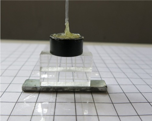
Figure 3 Measured and theoretical force
that the cuboidal magnet exerted on the magnet ring.
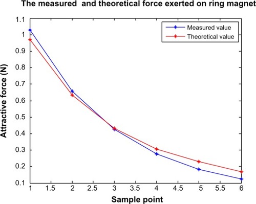
Table 1 Measured forces that the cuboidal magnet exerted on the magnet ring
Shape’s effect on force
It is meaningful to find relationships between each shape parameter and the force −
. If the relations are known in advance, a magnet of optimal shape can be made to obtain appropriate force. A cuboidal magnet has three shape parameters: length, width, and height. As any parameter may vary arbitrarily, it is inconvenient to investigate how the three parameters affect force at the same time. Therefore, we fixed the other two parameters while investigating one parameter’s effects on force variation.
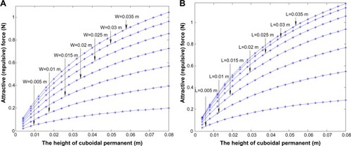
Firstly, the length or width of the cuboidal magnet is fixed, and the height changes. The force
variation trends with the cuboidal magnet’s height are shown in . It can be seen from that the force always increased with the increasing height of the cuboidal magnet, no matter what the width or length of the magnet was. An interesting thing that should be noted is that the magnitude of force
increased slowly with increasing width or length of the cuboidal magnet.
Figure 4 Force
variation versus the height of the cuboidal magnet
Abbreviations: W, width; L, length.
Secondly, the height or width of the cuboidal magnet was fixed, and the length varied. The force
variation trends with the cuboidal magnet’s length are shown in . This shows that the force increased with increasing length at the beginning, whatever the width or the height; after the force reached a maximum, it went down as the length continued to increase.
Figure 5 Force
variation versus the length of the cuboidal magnet
Abbreviations: W, width; L, length.
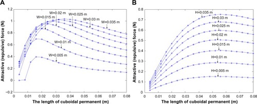
Thirdly, the height and length of the cuboidal magnet was fixed, and the width varied. The cuboidal magnet’s width effects on force
are shown in . We found that the force-variation trend was the same as that in .
Figure 6 Force
variation versus the width of the cuboidal magnet
Abbreviations: W, width; L, length.
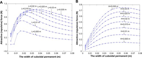
According to –, it can be concluded that force
will increase with the cuboidal magnet’s height, and the force will maximize when the width and length are certain values.
Conclusion and future work
Some scholars have testified that a remote magnetic maneuver for a robotic capsule enclosing a magnet is feasible. The problem is that the volume of the robotic capsule is limited, because the batteries, circuits, camera, etc are incorporated. If an extra magnet is contained within it, system integration will be quite challenging. Expansion of the dimensions of a robotic capsule makes it hard to swallow. To address this problem, we propose that the capsule is looped by a magnet ring of 1 mm thickness, and maneuvered by a cuboidal magnet.
In this paper, we presented a mathematical model of force that a permanent magnet exerts on another permanent magnet. The experiments showed that the measurement values were in agreement with the theoretical values. The experiments also showed that the magnetic force can be adjusted by changing the dimensions of the cuboidal magnet. According to the mathematical model, the optimal cuboidal magnet can be calculated accurately in advance. In the future, we will investigate the cylindrical magnet’s force on the magnet ring, and we will also study the force that the new robotic capsule needs when it moves forward in the whole GI tract.
Acknowledgments
This project was supported by the National Natural Science Foundation of China (grants 61202196, 61202195), the China Scholarship Council, Key Project of Sichuan Education Department (grant 12ZA200), Yibin Scientific and Technological Project (grant 2013ZSF010), and also by the doctoral fund of Yibin University (grant 2011B06).
Disclosure
The authors report no conflicts of interest in this work.
References
- Given Imaging [website on the Internet] Available from: http://www.givenimaging.comAccessed March 29, 2014
- RF. The next generation capsule endoscope – Sayaka Available from: http://www.rfsystemlab.com/en/sayakaAccessed March 29, 2014
- Jinshan Science and TechnologyCapsule robot Available from: http://www.jinshangroup.com/产品中心/胶囊机器人/tabid/67/Default.aspxAccessed March 29, 2014
- IddanGMeronGGlukhovskyASwainPWireless capsule endoscopyNature200040541710839527
- CiutiGMenciassiADarioPCapsule endoscopy: from current achievements to open challengesIEEE Rev Biomed Eng20114597222273791
- MenciassiAQuiriniMDarioPMicrorobotics for future gastrointestinal endoscopyMinim Invasive Ther Allied Technol2007169110017474052
- CiutiGValdastriPMenciassiADarioPRobotic magnetic steering and locomotion of capsule endoscope for diagnostic and surgical endoluminal proceduresRobotica201028199207
- CiutiGDonlinRValdastriPRobotic versus manual control in magnetic steering of an endoscopic capsuleEndoscopy20104214815220017088
- MahoneyAWAbbottJJ5-DOF manipulation of a magnetic capsule in fluid using a single permanent magnet: proof-of-concept for stomach endoscopy2013 Available from: http://www.telerobotics.utah.edu/uploads/People/Mahoney_Hamlyn_Poster.pdfAccessed March 29, 2014
- KellerJFibbeCVolkeFRemote magnetic control of a wireless capsule endoscope in the esophagus is safe and feasible: results of a randomized, clinical trial in healthy volunteersGastrointest Endosc20107294194620855064
- ReyJFOgataHHosoeNFeasibility of stomach exploration with a guided capsule endoscopeEndoscopy20104254154520593331
- KellerHJuloskiAKawanoHMethod for navigation and control of a magnetically guided capsule endoscope in the human stomachPoster presented at: Biomedical Robotics and Biomechatronics, 4th IEEE RAS and EMBS International ConferenceJune 24–27, 2012Rome, Italy
- LiaoZDuanXDXinLFeasibility and safety of magnetic-controlled capsule endoscopy system in examination of human stomach: a pilot study in healthy volunteersJ Interv Gastroenterol2012215516023687601
- HuCYangWAChenDMMengQHHoude DaiHAn improved magnetic localization and orientation algorithm for wireless capsule endoscopePoster presented at: 30th Annual International IEEE EMBS ConferenceAugust 20–24, 2008Vancouver, BC
- HuCMengQHMandalMA linear algorithm for tracing magnet’s position and orientation by using 3-axis magnetic sensorsIEEE Trans Magn20074340964101
- YangWAChaoHMengQHSongSDaiHA six-dimensional magnetic localization algorithm for a rectangular magnet objective based on a particle swarm optimizerIEEE Trans Magn20094530923099
- YangWAHuCMengQHDaiHChenDA new 6D magnetic localization technique for wireless capsule endoscope based on a rectangle magnetChin J Electron201019360364
- SidhuRSandersDSMcAlindonMEGastrointestinal capsule endoscopy: from tertiary centres to primary careBMJ200633252853116513710
- AgasheJSArnoldDPA study of scaling and geometry effects on the forces between cuboidal and cylindrical magnets using analytical force solutionsJ Phys D Appl Phys200841105001
- WangsnessRKElectromagnetic FieldsNew YorkWiley1986
- GouXFYangYZhengXJAnalytic expression of magnetic field distribution of rectangular permanent magnetsAppl Math Mech200425271278