
Abstract
Introduction
Sacroiliac (SI) joint pain has become a recognized factor in low back pain. The purpose of this study was to investigate the effect of a minimally invasive surgical SI joint fusion procedure on the in vitro biomechanics of the SI joint before and after cyclic loading.
Methods
Seven cadaveric specimens were tested under the following conditions: intact, posterior ligaments (PL) and pubic symphysis (PS) cut, treated (three implants placed), and after 5,000 cycles of flexion–extension. The range of motion (ROM) in flexion–extension, lateral bending, and axial rotation was determined with an applied 7.5 N · m moment using an optoelectronic system. Results for each ROM were compared using a repeated measures analysis of variance (ANOVA) with a Holm–Šidák post-hoc test.
Results
Placement of three fusion devices decreased the flexion–extension ROM. Lateral bending and axial rotation were not significantly altered. All PL/PS cut and post-cyclic ROMs were larger than in the intact condition. The 5,000 cycles of flexion–extension did not lead to a significant increase in any ROMs.
Discussion
In the current model, placement of three 7.0 mm iFuse Implants significantly decreased the flexion–extension ROM. Joint ROM was not increased by 5,000 flexion–extension cycles.
Keywords:
Introduction
Low back pain is a significant cause of disability, resulting in 45 million patient visits in 2006.Citation1 Studies have reported that the sacroiliac (SI) joint is a pain generator in 14.5%–22.5% of patients reporting low back pain.Citation2,Citation3 Prior fusion of the lumbar spine is a factor that has exacerbated degeneration of the SI joint in up to 75% patients studied.Citation4 As the number of spine fusions continues to grow,Citation1 it can reasonably be expected that the incidence of SI joint pain will continue to grow.
Until recently, open fusion of the SI joint has been the primary option for SI joint arthrodesis. Recent advances in minimally invasive surgery and medical device technology have allowed for percutaneous fusion of the SI joint. This change to a minimally invasive procedure has led to both greater pain relief and better outcomes.Citation5 Additional clinical studies have reported promising results for percutaneous fusion of the SI joint.Citation6–Citation11
One system that allows for a minimally invasive procedure involves placement of a series of triangular implants across the SI joint (iFuse Implant System; SI-BONE, Inc., San Jose, CA, USA). The triangular implants are fabricated out of medical-grade titanium and are coated with a porous titanium plasma spray to allow for biological fixation. The implants are placed to allow for initial mechanical fixation and then rely on biological fixation to permanently stabilize the joint.
Although previous clinical studies have shown promising results, the biomechanics of the initial fixation have not been reported. The objective of this study was to investigate the effects of SI joint fusion on the biomechanics of the SI joint after initial fixation and after 5,000 cycles of flexion–extension.
Methods
Specimen preparation
Eight human cadaveric specimens were used in this study. Specimens were transected rostrally at L4 and included the lower lumbar spine, sacrum, and pelvis. Specimens were obtained fresh frozen and then thawed at room temperature and carefully cleaned of muscle tissue without damaging any ligaments, discs, or joint capsules, including the pubic symphysis. Plain X-ray films were taken to ensure that none of the specimens had any obvious radiographic flaws, visible flaws, or flaws noted on patient history (especially metastatic disease, osteophytes, disc narrowing, or joint arthrosis). Dual energy X-ray absorptiometry (DEXA) scans were performed on the L4 vertebra of each specimen to assess bone mineral density (BMD) and to ensure that none of the specimens had osteoporosis. Specimens were wrapped in plastic bags and stored at −20°C until tested.
On the night before and day of testing, the specimens were thawed for several hours at room temperature while being kept wrapped in saline-soaked gauze. For testing, household screws were inserted into various locations in the exposed L4 endplate and facet articulations, and these screw heads were embedded in fast-curing resin (Smooth Cast 300Q; Smooth-On, Inc., Easton, PA, USA) in a cylindrical potting fixture for application of loads. Similarly, screws were inserted near the right and left ischia on the pelvis and the screw heads were embedded in two separate (right and left) blocks of resin. Each of these resin blocks was of such a shape so that it could be clamped in a vise securely attached to the bottom of the servohydraulic test frame (MTS Systems Corporation, Eden Prairie, MN, USA), while giving free access to instrumentation sites.
Test procedure
The specimens were tested under four conditions: intact, cut posterior ligaments and pubic symphysis, treated, and after 5,000 cycles of flexion and extension.
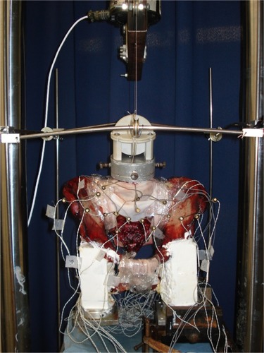
Under all conditions tested, specimens were studied using standard pure moment flexibility tests in single leg stance. For these tests, an apparatus was used in which a system of cables and pulleys imparts nondestructive, non-constraining torques in conjunction with a standard servohydraulic test system, as described previously.Citation12 A pure moment is distributed evenly to each motion segment, regardless of the distance from the point of loading.Citation13 Moments of 7.5 N · m maximum were applied about the appropriate anatomical axes to induce three different types of motion: flexion–extension, lateral bending, and axial rotation. Single leg stance was modeled by clamping the resin block attached to the ipsilateral acetabulum in the vise and letting the resin block attached to the acetabulum on the contralateral side hang freely (). All range of motions (ROMs) were calculated using a motion analysis system and custom software (as detailed below).
Figure 1 Photograph of the experimental test setup as configured for flexion testing.
After completion of testing the intact condition, a simulated instability was used to reduce the stability of the SI joint. This reduction was accomplished by sectioning the posterior ligaments (including the capsule) and the pubic symphysis. The loading protocol was repeated and the ROMs were calculated for the reduced stability condition.
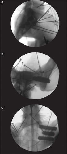
For the treated condition, all implants (iFuse Implant 7.0 mm; SI-BONE, Inc.) were placed according to the manufacturer’s recommendations. Briefly, the implants were placed using a pin, drill, broach, and implant methodology. A guide pin was placed under fluoroscopic guidance using the appropriate views (lateral, inlet, and outlet). The length of the implant was measured after placement of the pin. Next, a drill was used to prepare a hole that was broached to allow for placement of the implant. The second and third implants were placed parallel to the initial implant and approximately parallel to the posterior wall of the spinal canal (). After treatment was completed, the ROMs were determined using the previously defined loading protocol.
Figure 2 Representative fluoroscopic images showing placement of the three 7.0 mm implants placed in the (A) lateral, (B) inlet, and (C) outlet views.
Abbreviation: LED, light-emitting diode.
To determine the cyclic stability of the treated specimens, 5,000 cycles of flexion and extension were applied. The peak moment for cyclic loading varied between 3.75 and 7.5 N · m (). After cyclic loading was completed, the loading protocol was repeated and ROMs calculated.
Table 1 Specimen information and testing parameters
Motion analysis
Three-dimensional specimen motion in response to the applied loads during flexibility tests was determined using the Optotrak 3020 system (Northern Digital, Waterloo, ON, Canada). This system stereophotogrammetrically measures the three-dimensional displacement of infrared-emitting markers rigidly attached in a non-collinear arrangement to six regions on the lumbar spine and pelvic ring, including L4, L5, the sacrum (two locations), and the right and left ilia. Custom software converts the marker coordinates to angles about each of the anatomical axes in terms of the motion segment’s own coordinate system.Citation14 The coordinate system for each pair of marker triads was aligned to the anatomy of L5, with the lateral axis (x) aligned with points near the intersection of the pedicle and vertebral body, and the anteroposterior (z) axis aligned by interconnecting a midsagittal point at the anterior base of the L5 vertebral body to a point on the spinous process (this vector was aligned by eye to the L5–S1 rostral endplate). Spinal angles were calculated using a technique that provides appropriate results for describing three-dimensional spinal motion.Citation15
Data analysis
From the data, the angular ROM was generated. Analysis was performed on raw values (in degrees) or normalized values. Statistical comparisons were made with SigmaPlot (v12.5; Systat Software, Inc., San Jose, CA, USA).
A repeated measures analysis of variance (ANOVA) was used to analyze the outcomes between treatments. Post-cyclic values from the three peak moments were pooled for the repeated measures ANOVA. A Holm–Šidák post-hoc test was used to determine significant differences between groups. Linear regression was used to analyze the correlation between the maximum moment and change in normalized ROM. P-values less than 0.05 were considered significant.
Results
Seven specimens completed the testing (). One specimen (SI11) deteriorated during testing and was unable to complete the testing protocol; it was not included in the subsequent analysis.
Sectioning of the posterior ligaments and pubic symphysis resulted in significant increases in flexion–extension (P<0.001), lateral bending (P<0.001), and axial rotation ROMs (P<0.001) ( and ). Placement of the implants led to a significant decrease from the cut condition in flexion–extension (P=0.045), but not lateral bending (P=0.083) or axial rotation ROM (P=0.058). Cyclic loading of the specimens did not result in any significant changes from the implanted condition for flexion–extension (P=0.403), lateral bending (P=0.408), or axial rotation (P=0.697).
Figure 3 Flexion–extension, lateral bending, and axial rotation ROM data for seven SI joint specimens tested with pure moment loading.
Abbreviations: PL, posterior ligaments; PS, pubic symphysis; ROM, range of motion; SD, standard deviation; SI, sacroiliac.
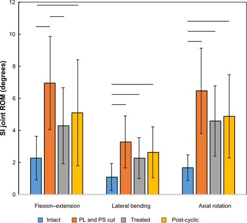
Table 2 Sacroiliac joint ROM testing results for seven specimens
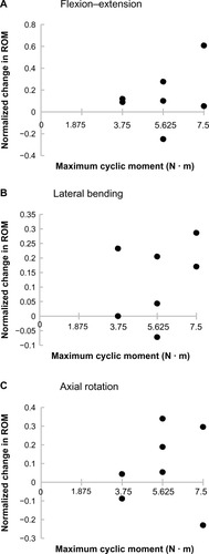
The correlations between the maximum moment during cyclic loading and the change in the ROM between implanted and post-cyclic samples were not significant for flexion–extension (P=0.435), lateral bending (P=0.466), or axial rotation (P=0.816; ).
Figure 4 Normalized change in the SI joint ROM after 5,000 flexion–extension loading cycles as a function of maximum cyclic moment for (A) flexion–extension, (B) lateral bending, and (C) axial rotation.
Abbreviations: ROM, range of motion; SI, sacroiliac.
Discussion
The in vitro biomechanical model here presents ROM data that is consistent with previous clinical studies.Citation16–Citation19 In the current study, it was found that in the intact condition, the magnitude of SI joint motion that occurred normally was largest in flexion–extension (2.3°), then axial rotation (1.7°), and smallest in lateral bending (1.1°). Egund et al found in an examination of four patients presenting with low back pain that testing with symmetric forces typically rotated the sacrum around the transverse axis up to 2°.Citation16 Sturesson et al investigated 25 symptomatic patients aged 18–45 years and found flexion–extension rotations ranging from 0.6° to 3.6°.Citation17 Jacob and Kissling investigated healthy individuals 20–50 years of age and found flexion–extension rotations from 0° up to 4.4°.Citation18 Sturesson et al also investigated six female patients aged 28–35 years with pelvic pain and found that hyperextension of the leg could lead to flexion–extension values up to 3.9°.Citation19 These studies consistently report that the ROM is largest in flexion–extension, then axial rotation, and smallest in lateral bending.Citation17–Citation19
A direct comparison of angles measured here to those from previous in vitro studies is not possible because other researchers did not quantify angular ROM in response to loads intended to produce planar rotational responses or use pure moments. Typical tests in prior in vitro studies ignored bending (or measured only slight bending secondary to compression).Citation20–Citation23 Other studies have applied offset compression to induce bending.Citation24,Citation25 A few studies have included pure moments in conjunction with follower loads to analyze the motion of the SI joint.Citation26–Citation28 The use of a follower load is thought to stabilize the spine, although its appropriateness is debated. By not including a follower load, the accuracy and consistency of the pure moment loading can be assured.
Cutting the posterior ligaments and pubic symphysis led to significant increases of flexion–extension, lateral bending, and axial rotation. The sectioning of these led to values that are consistent with those reported for motions reported with extreme hip positions in normal cadaver joints.Citation29 One concern was that this destabilization of the joint may lead to further degradation. Although one specimen did degrade, seven of the specimens continued to be stable and allowed for testing of the fusion devices and subsequent cyclic testing.
Placement of the fusion devices led to a significant decrease in flexion–extension. As previously detailed, flexion–extension is the dominate motion of the SI joint for the given loads. Reduction in joint motion is the primary goal and keeping this reduction will likely improve biological fixation. Although not significant, lateral bending was decreased in five out of seven specimens and axial rotation was decreased in all specimens, suggesting that the implants are effective in a large percentage of specimens. The cause of the increase in lateral bending in two out of seven specimens is unclear and is of interest for further investigation.
Cyclic loading of the treated SI joint did not lead to any significant changes in flexion–extension, lateral bending, or axial rotation ROMs. For the tested maximum moments, this suggests that no loosening of the SI joint was observed. Extrapolation of the cyclic results to the clinical condition must be made with caution. As with all in vitro models, it is not possible to investigate the results that the biological response will have on the stability of the treated SI joint.
The current study is not without limitations. The investigated model included sectioning of the posterior ligaments and the pubic symphysis. This study was set up to investigate a single SI joint and the effects of a fusion procedure on that joint. As such, the model in this investigation does not purely reflect the clinical condition as the pubic symphysis would likely be repaired. The resulting ROM data here are larger than the condition with the pubic symphysis intact. Although that model does warrant further investigation, the authors believe that the results of this study will translate to that condition.
Conclusion
The use of pure-moments in the reported pelvic model produced flexion–extension, lateral bending, and axial rotation SI joint ROMs that are consistent with previous clinical results. Simulated instability of the posterior ligaments and pubic symphysis led to significantly increased ROMs. After simulating an instability, placement of three SI fusion devices significantly reduced the flexion–extension ROM. Post-implantation cyclic loading did not result in any significant ROM changes in flexion–extension, lateral bending, or axial rotation. The use of the tested fusion devices provided for a more stable construct that did not significantly degrade during cyclic loading.
Disclosure
This study was funded by SI-BONE, Inc., Derek P Lindsey and Scott A Yerby are SI-BONE, Inc., employees. Neil R Crawford received research grant support (paid directly to the institution) from SI-BONE, Inc. The authors have no other conflicts of interest to report in this work.
References
- United States Bone and Joint InitiativeThe Burden of Musculoskeletal Diseases in the United States2nd edRosemont, ILAmerican Academy of Orthopedic Surgeons2011
- SembranoJNPollyDWJrHow often is low back pain not coming from the back?Spine (Phila Pa 1976)2009341E27E3219127145
- BernardTNJrKirkaldy-WillisWHRecognizing specific characteristics of nonspecific low back painClin Orthop Relat Res19872172662802951048
- HaKYLeeJSKimKWDegeneration of sacroiliac joint after instrumented lumbar or lumbosacral fusion: a prospective cohort study over five-year follow-upSpine (Phila Pa 1976)200833111192119818469692
- SmithAGCapobiancoRCherDOpen versus minimally invasive sacroiliac joint fusion: a multi-center comparison of perioperative measures and clinical outcomesAnn Surg Innov Res2013711424172188
- Al-KhayerAHegartyJHahnDGrevittMPPercutaneous sacroiliac joint arthrodesis: a novel techniqueJ Spinal Disord Tech200821535936318600147
- CummingsJJrCapobiancoRAMinimally invasive sacroiliac joint fusion: one-year outcomes in 18 patientsAnn Surg Innov Res2013711224040944
- RudolfLSacroiliac joint arthrodesis-MIS technique with titanium implants: report of the first 50 patients and outcomesOpen Orthop J2012649550223284593
- DuhonBSCherDJWineKDLockstadtHKovalskyDSooCLSafety and 6-month effectiveness of minimally invasive sacroiliac joint fusion: a prospective studyMed Devices (Auckl)2013621922924363562
- MasonLWChopraIMohantyKThe percutaneous stabilisation of the sacroiliac joint with hollow modular anchorage screws: a prospective outcome studyEur Spine J201322102325233123686478
- SachsDCapobiancoRMinimally invasive sacroiliac joint fusion: one-year outcomes in 40 patientsAdv Orthop2013201353612823997957
- CrawfordNRBrantleyAGDickmanCAKoenemanEJAn apparatus for applying pure nonconstraining moments to spine segments in vitroSpine (Phila Pa 1976)19952019209721008588165
- PanjabiMMBiomechanical evaluation of spinal fixation devices: I. A conceptual frameworkSpine (Phila Pa 1976)19881310112911343206270
- CrawfordNRDickmanCAConstruction of local vertebral coordinate systems using a digitizing probe. Technical noteSpine (Phila Pa 1976)19972255595639076889
- CrawfordNRYamaguchiGTDickmanCAA new technique for determining 3-D joint angles: the tilt/twist methodClin Biomech (Bristol, Avon)1999143153165
- EgundNOlssonTHSchmidHSelvikGMovements in the sacroiliac joints demonstrated with roentgen stereophotogrammetryActa Radiol Diagn (Stockh)1978195833846717034
- SturessonBSelvikGUdénAMovements of the sacroiliac joints. A roentgen stereophotogrammetric analysisSpine (Phila Pa 1976)19891421621652922636
- JacobHAKisslingROThe mobility of the sacroiliac joints in healthy volunteers between 20 and 50 years of ageClin Biomech (Bristol, Avon)1995107352361
- SturessonBUdenAVleemingAA radiostereometric analysis of the movements of the sacroiliac joints in the reciprocal straddle positionSpine (Phila Pa 1976)200025221421710685486
- DujardinFHRoussignolXHossenbaccusMThomineJMExperimental study of the sacroiliac joint micromotion in pelvic disruptionJ Orthop Trauma20021629910311818804
- SchildhauerTALedouxWRChapmanJRHenleyMBTencerAFRouttMLJrTriangular osteosynthesis and iliosacral screw fixation for unstable sacral fractures: a cadaveric and biomechanical evaluation under cyclic loadsJ Orthop Trauma2003171223112499964
- SagiHCOrdwayNRDiPasqualeTBiomechanical analysis of fixation for vertically unstable sacroiliac dislocations with iliosacral screws and symphyseal platingJ Orthop Trauma200418313814315091266
- MearsSCSutterEGWallSJRoseDMBelkoffSMBiomechanical comparison of three methods of sacral fracture fixation in osteoporotic boneSpine (Phila Pa 1976)20103510E392E39520393387
- WoodKBSchendelMJOgilvieJWBraunJMajorMCMalcomJREffect of sacral and iliac instrumentation on strains in the pelvis. A biomechanical studySpine (Phila Pa 1976)19962110118511918727193
- KimJHHortonWHamasakiTFreedmanBWhitesidesTEJrHuttonWCSpinal instrumentation for sacral-pelvic fixation: a bio-mechanical comparison between constructs ending with either S2 bicortical, bitriangulated screws or iliac screwsJ Spinal Disord Tech201023850651220124912
- ShawJAMinoDEWernerFWMurrayDGPosterior stabilization of pelvic fractures by use of threaded compression rods. Case reports and mechanical testingClin Orthop Relat Res19851922402543967429
- ComstockCPvan der MeulenMCGoodmanSBBiomechanical comparison of posterior internal fixation techniques for unstable pelvic fracturesJ Orthop Trauma19961085175228915911
- YuBZhengZZhuangXBiomechanical effects of transverse partial sacrectomy on the sacroiliac joints: an in vitro human cadaveric investigation of the borderline of sacroiliac joint instabilitySpine (Phila Pa 1976)200934131370137519478657
- SmidtGLWeiSHMcQuadeKBarakattESunTStanfordWSacroiliac motion for extreme hip positions. A fresh cadaver studySpine (Phila Pa 1976)19972218207320829322317