
 ?Mathematical formulae have been encoded as MathML and are displayed in this HTML version using MathJax in order to improve their display. Uncheck the box to turn MathJax off. This feature requires Javascript. Click on a formula to zoom.
Abstract
Unlike forearm amputees, transhumeral amputees have residual stumps that are too small to provide a sufficient range of operation for their prosthetic parts to perform usual activities of daily living. Furthermore, it is difficult for small residual stumps to provide sufficient impact absorption for safe manipulation in daily living, as intact arms do. Therefore, substitution of upper limb function in transhumeral amputees requires a sufficient range of motion and sufficient viscoelasticity for shoulder prostheses under critical weight and dimension constraints. We propose the use of two different types of actuators, ie, pneumatic elastic actuators (PEAs) and servo motors. PEAs offer high power-to-weight performance and have intrinsic viscoelasticity in comparison with motors or standard industrial pneumatic cylinder actuators. However, the usefulness of PEAs in large working spaces is limited because of their short strokes. Servo motors, in contrast, can be used to achieve large ranges of motion. In this study, the relationship between the force and stroke of PEAs was investigated. The impact absorption of both types of actuators was measured using a single degree-of-freedom prototype to evaluate actuator compliance for safety purposes. Based on the fundamental properties of the actuators identified, a four degree-of-freedom robotic arm is proposed for prosthetic use. The configuration of the actuators and functional parts was designed to achieve a specified range of motion and torque calculated from the results of a simulation of typical movements performed in usual activities of daily living. Our experimental results showed that the requirements for the shoulder prostheses could be satisfied.
Introduction
A prosthesis can perform sensorimotor functions for an amputee. If every such function could be performed by a prosthesis, it would approach the usefulness of a healthy human limb, but this would increase the number of parts and devices required, which would increase the cost, weight, and difficulty of maintenance. Therefore, it is more realistic to provide a prosthesis that performs fewer functions than a real human limb. As such, prostheses including a terminal device and a control system should be developed with a focus on priorities most suitable for users, considering the usage conditions.Citation1 A previous studyCitation1 focused on issues concerning the usability of myoelectric controls and upper limb prostheses. For example, because unilateral arm amputees are considered able to perform many activities of daily living (ADLs) with their intact arm, it is reasonable to develop prostheses with functions that support bimanual coordination motions, except for one-handed ADLs. On the one hand, the forms of prostheses vary depending on the amputated limb. Research examples of prosthetic handsCitation2–Citation5 and other typesCitation6–Citation11 of prostheses have been reported. A shoulder prosthesis is difficult to develop because of the larger dimensions required. Unlike forearm amputees, transhumeral amputees have residual stumps that are too small to provide a sufficient range of operation for their prosthetic parts to perform usual ADLs. Further, it is difficult for small residual stumps to provide sufficient impact absorption for safe manipulation in ADLs, as intact arms do. Therefore, it is important that a shoulder prosthesis has a sufficient range of motion (ROM) and sufficient compliance for the required motions of the user. These requirements inevitably require a shoulder prosthesis to have more parts and actuators and to weigh more than a hand or elbow prosthesis. However, lightness is one of the most important features of a prosthesis. For example, it was reported that 58% of respondents to a questionnaire given to hemilateral forearm amputees about requirements and desired improvements on the hardware, services, and schemes for use of an electric upper limb prosthesis hoped for further reduction of the weight and price (multiple answers allowed) than functionality, appearance, or a public prosthetic supply system in Japan; moreover, almost all the respondents answered that the desirable weight should be less than 0.9 kg.Citation12 The development of a shoulder prosthesis is made difficult by the trade-off between functionality and lightness.
In other studies, higher degree-of-freedom (DOF) shoulder–arm prostheses driven by motors have been developed.Citation13–Citation15 In their paper, Fukaya et alCitation15 presented an effort to develop a 13-DOF shoulder prosthesis the whole weight of which was 3.885 kg, with a spherical ultrasonic motor. These prostheses are multifunctional, especially one that is an armCitation14 controlled using targeted muscle reinnervation, which is considered state-of-the-art technology. However, these prostheses are not light enough; each has a total weight of approximately 4–6 kg. Amputees prefer a prosthetic arm that weighs less.Citation12,Citation16 For example, Yokoyama et alCitation16 reported that a high-level upper limb amputee felt the prosthetic arm with a myoelectric hand of 1.7 kg to be heavy when wearing it. Another development in prostheses is the use of motors, which have become common and can potentially provide both a wide ROM and a stable output force. However, the motors that are usually used are not lightweight in comparison with their payload. Moreover, such motors lack back-drivability, which is important for safe use because of the strong torques and multistage reduction gear. This means that a prosthetic arm with insufficient compliance, for example, could cause unexpected injuries because the arm would not be able to absorb the impact of contacts or collisions but rather would transmit the impact force directly to the socket, ie, the user’s body. Although a motor can possess pseudocompliance through appropriate controls, the time delay involved in absorbing an impact remains an issue. Because the time span of a collision impact’s peak value is very short, it would be ideal to be able to prevent any time delay. For example, development of robotic hands, arms, and medical devices with non-control-based and intrinsic flexibility that appear to be adaptable to prostheses has been proposed.Citation17–Citation20
Pneumatic elastic actuators (PEAs) have intrinsic flexibility. These are well suited to safe use in prostheses because they are both lightweight and soft, as a result of the viscoelasticity of air and rubber, and thus provide impact absorption without a time delay. PEAs do not need any additional passive elements for safety purposes. The use of PEAs could significantly reduce the weight and volume of a prosthesis. A smaller volume improves the appearance of a prosthesis, which is a key design consideration. Moreover, according to Plattenburg et al, PEAs offer high power-to-weight performance in comparison with motors or standard industrial pneumatic cylinder actuators.Citation3,Citation21,Citation22 Given the necessary characteristic features of a prosthesis, incorporation of PEAs could be useful in minimizing weight while providing a high output force and sufficient compliance for impact absorption. However, it is difficult to achieve a sufficient ROM with a PEA because of the short stroke (shrinkage length) and antagonistic mechanism (AM) required in a joint composed of PEAs. In addition, the output force is not necessarily stable with respect to the stroke. A motor offers advantages over PEAs in terms of the larger ROM possible, which contributes to a larger working space for the prosthesis and a stable output force (torque). Therefore, it is possible to use PEAs for designing ideal shoulder prostheses in combination with a motor to exploit the advantages of each and compensate for their respective shortcomings.
In this study, a hybrid lightweight shoulder prosthesis that uses the two aforementioned types of actuators was designed. In the design of the shoulder prosthesis, the layout of the two types of actuators was optimized to produce a lightweight device with sufficient compliance, ROM, and output force. The properties of the two types of actuators were first compared. The relationship between the force and shrinkage length of a PEA was investigated empirically. The impact absorption characteristics of both types of actuators were measured using a simplified 1-DOF arm and prototype measuring system.
In this study, we developed a 4-DOF linked arm model for the shoulder prosthesis and simulated the required rotational angle and torque of the joints by making the arm model track a certain pathway considered to represent a typical ADL motion. The layout of the two types of actuators in the joints of the model was determined from the results of the simulation. We confirmed that the PEA and the joint combined with it in the 1-DOF arm had better impact absorption properties than the motor and that the 4-DOF linked arm model was able to track the intended pathway and enhance the impact absorption properties of the prototype. The layout of the hybrid actuators in the joints was based on the results of the simulation and experiments.
A design procedure that considers the working space, safety, lightness, and torque of a shoulder prosthesis is described in this paper, and the design of a hybrid shoulder prosthesis developed using the procedure is presented. Basically, the ROM, compliance (for impact absorption), arm lightness, output torque, speed and stiffness of hand and joint, energy consumption, volume, and weight of a wearable power supply are considered as requirements for development of prostheses. These factors are closely related. In this study, the impact absorption, arm weight, and ROM requirements were to be satisfied through hybridization of two different types of actuators; meanwhile, the torque and volume requirements were also met, considering typical ADL movements, so this study contributes to the development of robotic arms for prosthetic uses. Other requirements are to be addressed in a subsequent project. The definitions of symbols used frequently in this paper are shown in .
Table 1 Definition of symbols used frequently in this paper
Materials and methods
Characteristics of PEA
Compliance (impact absorption)
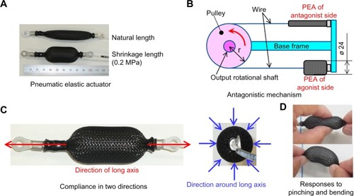
In this study, the PEA (PM-10P, SQUSE Inc.) shown in was employed. This is lightweight (0.003 kg) and has a high output force (maximum pulling force 100 N) and average shrinkage ratio of 30% per piece. These data are shown in its product catalog.Citation23 The maximum power-to-mass ratio is 33.3 kN/kg. This actuator makes it possible to generate a force only in flexion. Therefore, a unidirectional translational motion of the PEA can be converted into a bidirectional rotational motion using an AM, as shown in , and the actuator can be used in the joint of the prosthesis. In addition, the actuator has compliance in both the long axial direction and the direction around the long axis (perpendicular to the external surface of the actuator), as shown in and . Therefore, placing PEAs around the base frame, mimicking a mechanism of human muscles and bony framework, as shown in , gives rise to the possibility of absorbing impact force to a user’s body when the prosthetic arm collides with external objects. These characteristics were confirmed in the experiments described in a later section. Use of PEA is considered to contribute to compliance, ie, safe use of a prosthesis.
Figure 1 Characteristics of PEA.
Abbreviations: AM, antagonistic mechanism; PEA, pneumatic elastic actuator.
Spring constant
It is necessary to determine the relationship between the traction force Ft and the shrinkage length xsl of the PEA, ie, the spring constant k required to calculate the required joint torque and rotational angle of the AM in the shoulder prosthesis. The equation was assumed to be a linear function of the following form, where the constant is denoted by c.
(1)
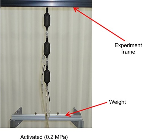
The method used is shown in . Three pieces of PEAs were connected serially for averaging purposes. The upper end of the series of PEAs was fixed to the test frame. Weights from 9.8 N to 98 N (10 kg; acceleration due to gravity g =9.8 m/sec2) were added in increments of 9.8 N (1 kg) to the lower end of the series of PEAs, and air pressure was conveyed to the actuators at a maximum value of 0.2 MPa. The change in length xsl with respect to the unloaded natural length of each PEA piece was measured under each weight. Because PEAs exhibit characteristics of hysteresis, this was also measured.
Figure 2 Measurement of spring constant.
Abbreviation: PEA, pneumatic elastic actuator.
Comparison between PEA and motor
An experiment was conducted to assess the effect of compliance in embedding a PEA in a prosthesis. The compliance was evaluated in terms of the level of absorption of an impact force from an external collision. This was measured in both the long axial direction and the direction around the long axis of the PEA, as shown in . For the long axial direction, an AM consisting of PEAs was developed, and the level of absorption of the impact force on the output rotational shaft of the AM was compared with that of a motor.
Direction around long axis
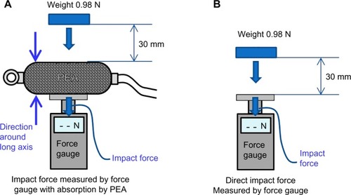
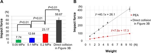
The method used to test the impact absorption of a PEA in the direction around its long axis is shown in . First, the PEA was tested using a force gauge (FGP-50,Citation24 Nidec-Shimpo Corporation, ±500 N), with the external surface of the PEA placed on the measurement surface of the force gauge, as shown in . A weight of 0.98 N was dropped from a height of 30 mm and collided with the surface of the PEA (in the direction around long axis), and the impact force was measured. A weight of 0.98 N was also dropped from a height of 30 mm and collided with the measurement surface directly, without the PEA in place. In this way, the effect of the PEA in the impact force absorption was confirmed. This test was performed using air pressures of 0.05, 0.1, and 0.2 MPa. The weight was connected to a slider and traveled along the slider’s rail as it fell. For the cases of a 0.2 MPa air pressure in the PEA and direct impact, weights from 0.98 N to 9.8 N (1 kg) were applied in increments of 0.98 N, and the trend of response with increasing load was examined. As described in detail later in this paper, if a significant difference exists in impact absorption with and without the PEA, the need to place PEAs around the base frame (link), as shown in , is confirmed.
Figure 3 Measuring compliance in direction around long axis.
Abbreviation: PEA, pneumatic elastic actuator.
Direction of long axis
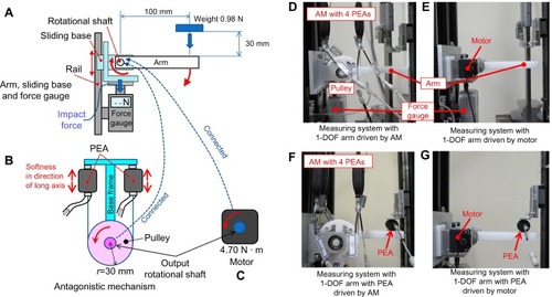
The method used to measure the impact absorption of the PEA in the direction of the long axis is illustrated in . The 1-DOF arm was prepared as shown in . The arm was linked to the sliding base with a rotational shaft and ball bearings. The sliding base was placed on the measurement surface of the force gauge. The sliding base was not fixed to the measurement surface but rather positioned on the surface in a way that allowed it to slide up and down on the slide rail. The output shaft of the AM with the PEAs (shown in ) or the motor (RS405CB,Citation25 Futaba Corporation, 0.067 kg, 4.7 N · m (48.0 kg · cm; shown in ) was connected to the arm’s rotational shaft. A weight of 0.98 N was dropped from a height of 30 mm and collided with the arm, as shown in , and the impact forces were measured. The degrees of impact absorption along the rotational axis, ie, the joints consisting of the motor and the AM, were compared, ie, the compliance in the direction of the long axis of the PEAs making up the AM was compared with that of the motor. As described in the previous section, air pressures of 0.05, 0.1, and 0.2 MPa were used. The measuring system is shown in .
Figure 4 Measuring compliance of PEA in direction of long axis with and without PEA in direction around long axis.
Abbreviations: AM, antagonistic mechanism; PEA, pneumatic elastic actuator; 1-DOF, single degree-of-freedom.
Combination of two directions
show the PEA in place for testing in the configurations shown in , respectively, ie, the combination of the impact absorption of the joint provided by the PEA and motor with the absorption of the PEA in the direction around its long axis was confirmed. The weight on the PEA and the air pressure of the PEA were 0.98 N and 0.2 MPa, respectively.
Modeling
Configuration of 4-DOF link arm model
In this study, a two-link arm model with four DOFs was developed, as shown in . The two links were the LU of the upper arm and the LFH of the forearm with the hand. Two DOFs were established in the shoulder (two joints, J1 and J2) and two in the elbow (two joints, J3 and J4). Although 1-DOF grasping capability is normally established for the hand, this was not a factor considered in the simulation conducted to optimize the actuator layout in this study. This weight and geometry (described later) were used just to create a complete shoulder prosthesis. Hand-to-mouth and hand-to-face movements, such as those involved in eating and hygiene activities, are important movements required for a prosthesis in daily living. For such movements, a larger angle of flexion of the elbow joint is assumed to be required, and this was confirmed in the simulation. In this study, we assumed that the prosthesis being developed would not be adapted for amputees immediately but rather for healthy subjects first to validate the design and its performance to some extent. Therefore, body surface data for the shoulder to the hand of one healthy subject (170.5 cm tall) were scanned and acquired using a three-dimensional scanner (Artec MHT), and a socket fitting the shoulder was designed assuming the prosthesis would be worn as shown in . Movement of the prosthetic arm was simulated under these conditions. The link length was based on the arm length determined from the scanned data, as shown in . The weight of the link model was based on that of a similar prototype arm that we developed in previous researchCitation26,Citation27 and the target weight was 1.0 kg. The load at the hand was assumed to be 4.9 N, considering a realization of typical ADL hand-to-mouth movements such as drinking a glass of water.
Figure 5 Arm link model of shoulder prosthesis.
Abbreviations: 3D, three-dimensional; 4-DOF, four degrees-of-freedom.
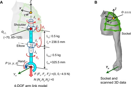
Calculating of joint angle and torque
As shows, the origin of the global coordinate system O-XYZ was placed at the left acromion. The intersection point of J1 and J2 in O-XYZ, the length of the link L (LU, LFH), the joint angle J (J1, J2, J3, J4), and the coordinates of the hand position (ie, the end tip of LFH) were defined as OJ1J2, l (lU, lFH), ϕ (ϕ1, ϕ2, ϕ3, ϕ4), and P (x, y, z), respectively. The following equations were used to simulate the required angle ϕ and torque T (T1, T2, T3, T4) of each joint in the link model. The relationship between ϕ, l, and P was calculated using Equationequation (2)(2) . EquationEquation (3)
(3) is the dynamic equation for the T of J, the external force F and ϕ. The ϕ was calculated by substituting the hand pathway into Equationequation (2)
(2) using a numerical solution, and T was derived by substituting ϕ into Equationequation (3)
(3) .
(2)
(3) H (ϕ): inertia term,
Coliolis term, Gf (ϕ): gravity term,
external force term including transposed Jacobian matrix, (F, N): external force F (Fx, Fy, Fz) and moment N (Nx, Ny, Nz) acting on P.Citation28
For the case of the AM for the joint J, shown in , Ft, and xsl of the PEA were derived by substituting the angle ϕ (in degrees) into Equationequation (4)(4) below using Equationequation (1)
(1) . Here, r is the radius of the pulley, ie, the moment arm, as shown in . The output torque of the AM, TAM (TAM1, TAM2, TAM3, TAM4), was calculated using Equationequation (5)
(5) .
(4)
(5)
Method for determining PEA configuration in AM and layout of PEA and motor in each joint
In applying Equationequation (5)(5) , one PEA piece on the agonistic side and one on the antagonistic side are considered, ie, two pieces in total, as shown in . It is possible that two PEA pieces are unable to provide the required torque T and joint angle ϕ, depending on the hand pathway superimposed on the link arm. In this case, multiple connected PEAs are required. The PEAs can be connected serially or in parallel, or in a combination of the two, in whatever manner the greatest output torque and rotational angle of the AM can be efficiently provided. The use of multiple PEAs is illustrated in . Let the number of serial and parallel connections in the joint J be ns (ns1, ns2, ns3, ns4) and np (np1, np2, np3, np4), respectively. EquationEquation (5)
(5) can be transformed into Equationequation (6)
(6) to reflect this situation. Finally, the selection between using PEAs or using a motor for each J is made on the basis of the calculated value of the total weight for the smallest number of PEAs, pulleys, and accessories to provide the required T and ϕ for each J, given the experimental results described in the section on direction around long axis. Although it is difficult to make a decision based on weight without consideration of the degree of impact absorption, in this study a servo motor was selected as an actuator in a joint to substitute an AM when the AM weighs more than two motors, ie, 0.134 kg (the weight of one motor is 0.067 kg). This weight-based decision criterion resulted from comprehensively considering the volume, weight, ROM, and appearance of prostheses. Although other small parts such as screws are necessary for the AM, the motor requires similar parts, so these were not considered in the comparison. The results presented in the previous section confirm the advantage of the PEA in terms of safety. The significant difference in impact absorption capacity of the PEA in the direction around its long axis, compared with that of direct impact (without a PEA), is confirmed by the experimental results described in the previous section. Therefore, the requirement for PEAs around the link (base frame), as shown in , was identified as a basic design principle. However, in the case of ns > 2, because the total length of PEAs in the direction of the long axis is greater than the link length l (lU, lFH), PEAs are not placed on the link L but rather on a backpack and actuated remotely using flexible Bowden cables. This backpack system was employed in our previous study.Citation26,Citation27 A bevel-gear drive box was employed when the base frame shown in was assumed to be the LFH in , because the axis direction between the pulley and the joint rotation differs from 90° in the relationship between J4 and LFH. The box’s weight must be determined. The radius r of the pulley in the AM in each J of the 4-DOF arm was set to 15 mm because the diameter of the PEA when compressed fully was approximately 24 mm, and the contraction of an agonistic PEA would interfere with the antagonistic PEA in the AM, when r was less than 12 mm, as shown in .
(6)
Figure 6 Case of multiple actuators in antagonistic mechanism [2 (ns × np) =8 pieces of actuator].
Abbreviation: AM, antagonistic mechanism.
![Figure 6 Case of multiple actuators in antagonistic mechanism [2 (ns × np) =8 pieces of actuator].](/cms/asset/25ae2f40-0cd0-422d-8804-e2eb616e6ed0/dmde_a_83756_f0006_c.jpg)
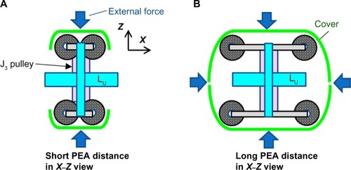
Confirmation of layout by CAD model
The layout of the actuators and the shape of the links were designed and validated using a computer-aided design (CAD) software model. The output impact force on the shoulder with respect to the input impact force on the link LU in the horizontal (X) and vertical (Z) directions in the case of the whole arm extending in the Y direction (ϕ2=90°) was estimated based on the results described in the section on combination of two directions. For example, when the base frame and the AM were assumed to be the LU and joint J3 in and , respectively, even for a fixed number of PEAs, the impact on the shoulder varies based on the layout of the PEAs. As shown in , assuming LU and LFH together are able to produce an effect of the PEAs in the direction around the long axis in response to an external impact force by overlaying the PEAs with the cover, the effects of impact absorption can be expected only in the vertical direction for the case shown in and in both the horizontal and vertical directions for the case shown in .
Figure 7 J3 antagonistic mechanism and LU with cover.
Abbreviation: PEA, pneumatic elastic actuator.
Hand pathway superimposed on link arm
The pathway of the hand (the end tip of LFH) that was superimposed on the link arm is shown in . The pathway was based on typical ADL hand-to-mouth movements in the horizontal and vertical direction, as shown in . The first plot () shows the pathway formed with straight lines (pathway A). A constraint condition was set such that the axis YH of the coordinate system of the hand in was always in the sagittal plane (the Y–Z plane with an arbitrary X position). This permits the hand to easily grasp an object, such as a bottle on a table. The velocity of the hand and the time interval of the points on the pathway were set to 0.45 m/sec and 0.0167 sec, respectively, based on observations of human ADL motion and the sampling frequency of 1/60 Hz of the motion capture system used in our previous study.Citation26
Figure 8 Comparison of three pathways.
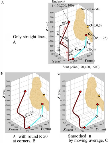
Because the torque was assumed to increase rapidly because of the dramatic change in the direction of the straight line at the corners in pathway A, another pathway (pathway B) was established in which the sharp corners were replaced with curves having radii of 50 mm, as shown in . A third pathway (pathway C) was established with the curves smoothed using a moving average of 10 points and three time repetitions as shown in . The required joint angle ϕ and torque T were simulated using Equationequations (2)(2) and Equation(3)
(3) for the arm tracking each of these pathways. These results were used to select the configuration of the PEAs in the AM, ie, to determine ns and np using Equationequation (1)
(1) and Equationequations (4)
(4) to Equation(6)
(6) .
Results
Experiments
Spring constant
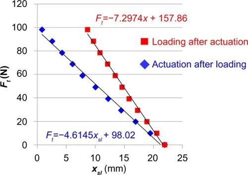
The relationship between the shrinkage length xsl with respect to the unloaded natural length of the PEA and the traction force Ft per PEA piece during actuation at 0.2 MPa is shown in . The blue and red curves correspond to the cases of actuation (application of air pressure) after adding the weight and adding the weight after actuation, respectively. The measurements were repeated ten times. There were differences between the two cases due to the influence of hysteresis. The stricter conditions represented by the blue curve were considered in the calculation of the spring constant. EquationEquations (1)(1) and Equation(6)
(6) were modified to reflect the measurement results indicated by the blue curve. Based on Equationequation (7)
(7) , the maximum pull force of each PEA is 98.02 N when fully extended (xsl = 0) although the one in its product catalogCitation23 is 100 N.
(7)
(8)
Figure 9 Relationship between xsl and Ft at 0.2 MPa.
Impact absorption in direction around long axis of PEA
The results of the impact tests in the direction around the long axis of the PEA are shown in . The test was conducted ten times. The graph shows the peak values of the force for air pressures of 0.05, 0.1, and 0.2 MPa, as shown in , and without the PEA (direct collision), as shown in . For the cases of an air pressure of 0.2 MPa and direct impact, the results for weights from 0.98 to 9.8 N (1 kg) are shown in . The results with and without the PEA are significantly different (P<0.01) for all six weight levels. Therefore, the requirement for PEAs placed around the link (the base frame) was confirmed as a basic principle, as described in the section outlining the method for determining PEA configuration in AM and layout of PEA and motor in each joint.
Figure 10 Comparison of peak impact force: with and without PEA in direction around long axis.
Abbreviation: PEA, pneumatic elastic actuator.
Impact absorption in direction of long axis of PEA in AM versus motor
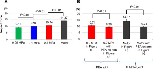
The results of the impact tests in the direction of the long axis of the PEA in the AM are compared with those for the motor in . The tests were repeated ten times. shows the peak values of the force on the arm with the PEA in the AM for air pressures of 0.05, 0.1, and 0.2 MPa, as shown in , and for the motor, as shown in . The air pressure of the PEA in the AM was initially set to 0.2 MPa. To achieve a torque of the AM at an air pressure of 0.2 MPa close to that of the motor (4.70 N · m), two PEAs were used in parallel on each side (ns =1 and np =2). The AM torque was calculated to be 4.74 N · m (for r=30 mm). The air pressure was subsequently decreased to 0.1 MPa and then 0.05 MPa. The peak values of the force on the arm with the PEA in the AM were decreased in comparison with the motor. The results between each PEA and the motor are significantly different (P<0.01).
Figure 11 Comparison of peak impact force at joint consisting of PEAs at each pressure and of motor with and without PEA on arm.
Abbreviation: PEA, pneumatic elastic actuator.
Impact absorption in direction of long axis of PEA in AM versus motor with and without PEA on arm
The results of the impact testing illustrated in and are shown in . The AM joint of PEAs with the PEA on the arm (shown in ) reduced the force to 87.4% of that of the same joint without the PEA (shown in ). The motor joint with the PEA () also reduced the force to 67.8% of that of the joint without the PEA ().
Modeling
Required torque and angle of joints
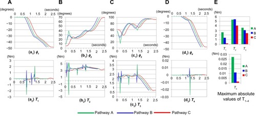
shows the required torques T (T1, T2, T3, T4) and angles ϕ (ϕ1, ϕ2, ϕ3, ϕ4) of the joints associated with following the three pathways shown in : with straight lines only (pathway A); with curves rounded and a radii of 50 mm (pathway B); and with smoothing performed using a moving average (pathway C). The maximum absolute values of the torques for pathway C were smaller for all of the joints than those for pathways A and B, as shown in . Therefore, pathway C was used to simulate the configuration of the AM using Equationequations (2)(2) , Equation(3)
(3) , and Equation(8)
(8) .
Figure 12 Comparison of required joint angle and torque in pathways (A–C).
Configuration of AM and motor layout in each joint
Based on the results for pathway C described in the section on required torque and angle of joints, the configuration of the AM in each joint was designed using Equationequations (2)(2) , Equation(3)
(3) , and Equation(8)
(8) , as shown in . The values of T, TAM, and ϕ are shown in . In , the number of required actuators is the total for both the antagonist and agonist sides in . Both positive and negative torques T1 and T4 in the coordinate system shown in were calculated. Absolute values of T1 and T4 are shown for comparison with TAM1 and TAM4 in . There are places at which TAM1 and TAM4 change suddenly as a result of a change in the side (antagonist or agonist in ) that should be activated. The AMs of J1,2,3 (but not J4) were set to rotate in one direction only with respect to the initial posture in the coordinate system shown in because the rotational direction of ϕ1,2,3 in is only in one direction (ϕ1, −; ϕ2, +; ϕ3, +; ϕ4, ±) as indicated by the “Required ϕ” in . On the other hand, because of the required rotational angle ϕ4 in both the positive and negative directions for J4, the AM of J4 was set to rotate in both directions. Therefore, the constraint for J4 was strict in comparison with that for J1,2,3, and a special method was employed only for J4. The absolute maximum rotational angle of the AM of J4, based on the configuration in , was initially 40.61°, which was less than the absolute maximum required ϕ4 of 46.75°. Thus, a gear train with a speed reduction ratio of 0.5 was employed to address the situation of J4. The absolute maximum angle of the AM of J4 was thereby increased to 81.22°, which exceeded the ϕ4 value of 46.75°. In turn, although the torque was reduced, the averages of the absolute values of TAM4 with the gear and T4 were 0.8365 Nm and 0.0003 Nm, respectively, and the TAM4 of the configuration met the requirement for T4. The total weight of the gear train and the bevel-gear drive box was 35 g.
Figure 13 Torque and joint angles.
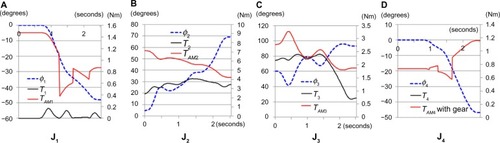
Table 2 Required number of actuators
Based on these results, because the total weight of the AM with the PEAs of J2 exceeded 0.134 kg, ie, the threshold selected as described in the section on the method for determining PEA configuration in AM and layout of PEA and motor in each joint, the motor drive was selected as a substitute for the AM only for J2.
Design and simulation of 4-DOF arm
Based on the results described in the previous section, the 4-DOF arm shown in was designed. Because of the significant differences in the results shown in the section on impact absorption in direction around the long axis of PEA, and and were confirmed, PEAs were placed around the link LU and LFH in the 4-DOF arm design. The PEAs of the AMs of J3 and J4 were placed on LU and LFH, respectively. Because neither J3 nor J4 had ns > 2, this placement was feasible, as described in the section on the method for determining PEA configuration in AM and layout of PEA and motor in each joint. The PEAs of the AM of J1 were placed on the backpack. The 1-DOF motor-driven hand with grasping capability (J5 in ), which was prototyped previously,Citation26 was incorporated into the design to make the shoulder prosthesis complete. The motors for the hand were also assumed to be set in the backpack.
Figure 14 Design of 4-DOF arm with 1-DOF hand based on the results of determining PEA configuration in AM, and layout of PEA and motor in each joint.
Abbreviations: AM, antagonistic mechanism; PEA, pneumatic elastic actuator; 4-DOF, four degrees-of-freedom; 1-DOF, single degree-of-freedom.
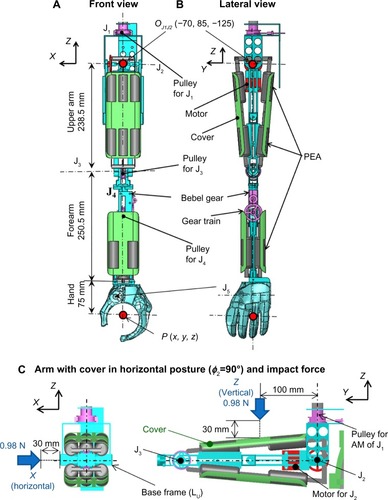
As shown in , the output impact forces on the shoulder with respect to the input impact forces to the link LU in the horizontal (X) and vertical (Z) directions in the case of the entire arm extending in the Y direction (ϕ2=90°) were estimated as shown in , based on the result described in the section on impact absorption in the direction of the long axis of PEA in AM versus motor with and without PEA on the arm and . Estimates based on the layout described in and for layouts composed of all PEA joints and all motor joints are shown for comparison. Because the upper arm LU was not designed as shown in but rather as shown in , the impact on the shoulder in the X direction in was estimated without the effect of impact absorption by the PEA around its long axis direction. This case corresponds to the results labeled “0.2 MPa in ” in .
Table 3 Impact force on shoulder in simulation
The weight of the arm in the simulation is shown in . For all components, except the hand and back pack, the weight calculated by CAD was used. For the hand and backpack, the weight of actual parts, manufactured for another project, was used. The arm weight could be estimated to be lower than 1 kg.
Table 4 Arm weight in simulation
Discussion
In this paper, the torque, impact absorption, and ROM of a shoulder prosthesis were investigated by both experiments and simulation. Two different types of actuators embedded in a 1-DOF arm were compared for the purpose of developing a shoulder prosthesis in which an adequate working range, output force, and impact absorption capacity were provided in a balanced manner based on the layout of the actuators. The characteristics of the PEAs used in the prosthesis were measured.
Experiments
The graph of the traction force Ft and the shrinkage length xsl in applies to the case of an air pressure fixed at 0.2 MPa. The relationship between Ft and xsl is approximately linear. Although T and TAM were calculated based on this result and Equationequation (1)(1) , the derivation of the relationship over the entire pressure range considered, eg, for increments of 0.01 MPa, would be desirable to improve the accuracy of the results. The next practical step would be to establish the parameters for a given air pressure.
With respect to impact absorption, the impact force in the direction around the long axis of the PEA (on the external surface) was found to be greatly decreased in comparison with a direct impact on the measurement surface of the force gauge, as shown in and . This trend continued with increasing weight. As shown in , the impact force with the PEA was approximately 20% of that of the direct collision. Therefore, use of PEAs can contribute to safe use of the prosthesis, and the design should include PEAs placed around the arm. Moreover, the impact force could be decreased by decreasing the air pressure. The relationship between air pressure, shrinkage length xsl, and degree of impact absorption, ie, the relationship between the joint angle, arm position, posture, and vulnerability to impact, should be studied further. The impact absorption capacity in the axial direction of the PEA in the AM with the 1-DOF arm was shown to be greater than that of the motor joint (see ) and to vary with air pressure, as shown in . Although a motor can generate pseudocompliance through motor control, the associated time delay is an issue. The intrinsic compliance of the actuator eliminates the time delay in absorbing an impact. To confirm this, continuous impact data along the temporal axis should be measured, and the influence of the time delay should be investigated. Moreover, the measured value for the 0.2 MPa PEA (10.74 N) and the value for direct collision (14.37 N) in was significantly decreased in comparison with the result (59.67 N) in under the same condition of input force in collision with the rigid part (the arm or measurement site of the force gauge) in , , and E. This is considered to be due to impact absorption by the joint and main body of the arm. Thus, the impact force is considered to increase as the collision position approaches the joint, ie, verging on the condition shown in . The shape of the main body of the arm must be validated. Further, the difference between the forces with and without the PEA on the arm (see and ) was not large in comparison with the difference between the force with the 0.2 MPa PEA and the direct collision (see ). However, the difference between the motor joint with and without the PEA was greater than that between the PEA joint with and without the PEA on the arm, as shown in . Therefore, even if a certain joint is driven by the motor, the impact is considered to be decreased by covering the arm body with the PEA of the other joint. The results shown in and indicate that the design could not absorb the impact force in the X direction using the external surface of the PEA. However, the force decreased in comparison with all of the motor joints as a whole because J1 was the PEA joint, as shown in . The effect of impact absorption could be confirmed by employing either a PEA joint or by placing PEAs around the arm.
Modeling
We next consider the results related to the pathways considered and the joint behavior while following the pathways. Using Equationequations (2)(2) and Equation(3)
(3) , the required angle ϕ and torque T were calculated for the three types of pathways, as shown in , and T was shown to be decreased by smoothing the pathway, as shown in . This indicates that planning the path of a motion affects the ideal layout of the actuators in the arms for a given motion. This problem also affects the output force of the actuator and the supply source (battery or air compressor) used, and thus should be taken into consideration.
In this paper, the threshold for selecting either the AM or motor was set to the weight of two motors (0.134 kg) based on one motor weighing 0.067 kg. In this way, the motor and the AM of the PEA were selected for J2 and the other joints, respectively. However, the selection is highly dependent on the threshold. For example, if the weight of one motor (0.067 kg) were used as the threshold, the AM of the PEA would only be selected for J1; if the weight of three motors (0.201 kg) were used as the threshold, the AM of the PEA would be selected for all of the joints. Moreover, although the pulley radius r for all of the joints was set to 15 mm, the TAM changes with r, as shown in Equationequation (8)(8) ; thus, the layout selection may change as the threshold changes. Further, the relationship between number of actuator connections (ns and np) and r is seemingly simple (for example, the value of TAM when np doubles seems to be equal to the value of TAM when r doubles, for a fixed value of ns). However, because r is present twice in Equationequations (4)
(4) and Equation(8)
(8) , ie. in r2 as well, the relationship becomes complex and should be investigated carefully. In this study, although the ratio of TAM to T was not considered, a factor of safety should be established. These factors should be considered in further optimization of the design.
In joint J4, a gear train with a speed reduction ratio of 0.5 was used. A PEA can exert large force when xsl is small, as shown in . Therefore, the PEA is considered to be of greater advantage for small ranges of motion. For example, in the case of ϕ4=20° without the gear and r=15 mm, TAM4 was calculated to 0.746 Nm. When the gear train was mounted and the angle of the output shaft of the train was set to ϕ4=20°, the required input pulley angle was only 10°, and the calculated TAM4 was 0.554 Nm. Although the output angle and speed are inversely proportional to the output torque in a normal gear train, in this case the output torque was greater than 50% (0.554/0.746=74.26%) when the output angle doubled. In the case of ϕ4=30°, the output TAM4 without and with the gear (for an input pulley angle of 15°) was 0.384 Nm and 0.464 Nm, respectively. That means that the output angle remained unchanged, and the output torque improved to 0.464/0.384 = 120.83%. Installation of a gear train has a disadvantage in that it increases the weight and may delay the response. However, this can be a useful trade-off depending on the rotational range.
Conclusion
In this study, a lightweight hybrid-type shoulder prosthesis in which PEAs are combined with a motor was designed to achieve an adequate working range, output force, and impact absorption capacity in a balanced manner. To design AMs of PEAs that have the potential to enhance the safety of prosthetic joints, the Ft–xsl relationship of the PEA was determined experimentally at the beginning of the study. A measuring system with a 1-DOF arm for use in investigating the feature of the two types of actuators was built, and the impact absorption capacity in both the long axial direction and around the long axis direction of the PEA was measured in collision experiments and compared with that of a motor. The results show that arranging PEAs throughout the arm makes it possible to achieve sufficient impact absorption capacity both inside the joints and on the external surface of the arm. This could reduce the impact force by approximately 35%, compared with all-motor configuration, as shown in .
A link model was developed and dynamic equations were derived to simulate the required angle ϕ and torque T as the arm tracked pathways corresponding to a typical ADL hand-to-mouth movement. The equation for the Ft−xsl relationship was used to develop a procedure for determining the required number of PEAs in the AM (ns and np). Finally, the actuator (PEA or motor) to be used in each shoulder and elbow joint was determined using a threshold based on the weight of the motor; the PEAs and motor were set for J1-J3-J4 [ns(1, –, 2, 1) and np(1, –, 3, 2)] and J2, respectively, as shown in . A CAD model was designed on the basis of the results of the layout analysis and collision experiments, and 10.74 and 9.47 N of the impact forces on the shoulder were estimated by applying a collision force to the upper arm in the horizontal and vertical directions against 14.37 N of all motor layout, respectively, as shown in . The arm weight could be estimated within 1 kg, as shown in . The problem of the trade-off between the output torque and the output angle was addressed by installing a gear train in the AM of one of the joints.
Future work
In this paper, although the simulation used typical pathways, various ADL motions of actual subjects should be measured, and those trajectories should be reproduced with a real prosthetic arm. Then, by examining the relationship between the various ADL movements and the optimal layouts of the actuators in the joints, useful information can be provided to other researchers and prosthetists concerning not only the required torques and angles to be simulated but also suitable actuator types for various ADL movements.
The dimensions and specifications of a prosthesis vary depending on the body habitus and the ADL movements needed by the user. Optimizing the pulley radius, gear ratio, and number and configuration of PEAs used is a future challenge in the development of the proposed prosthesis model. There is also an urgent need to establish control techniques to utilize these elements.
Acknowledgments
This work was primarily supported by the Japan Society for the Promotion of Science Grant-in-Aid for Scientific Research (B), Grant Number 26282160.
Disclosure
The authors declare no conflicts of interest in this work.
References
- OhnishiKImproving the usability of myoelectric controls and upper limb prosthesesBulletin of the Japanese Society of Prosthetics and Orthotics2011278488 Japanese
- PolisieroMBifulcoPLiccardoADesign and assessment of a low-cost, electromyographically controlled, prosthetic handMedical Devices: Evidence and Research2013697104
- PeerdemanBSmitGStramigioliSPlettenburgDHMisraSEvaluation of pneumatic cylinder actuators for hand prosthesesProceedings of the Fourth IEEE RAS and EMBS International Conference on Biomedical Robotics and Biomechatronics201211041109
- GonzalezJSomaHSekineMYuWPsycho-physiological assessment of a prosthetic hand sensory feedback system based on an auditory display: a preliminary studyJ Neuroeng Rehabil2012911422244362
- ZhangTFanSZhaoJDesign and control of a multisensory five-finger prosthetic handProceedings of the 11th World Congress on Intelligent Control and Automation201433273332
- LowCYKasimMAAKochTHybrid-actuated finger prosthesis with tactile sensingInternational Journal of Advanced Robotic Systems201310110
- YongXJingXJiangYTendon drive finger mechanisms for an EMG prosthetic hand with two motorsProceedings of Seventh International Conference on Biomedical Engineering and Informatics2014568572
- SittiwanchaiTNakayamaIInoueSTranshumeral prosthesis prototype with 3D printing and sEMG-based elbow joint control methodProceedings of the 2014 International Conference on Advanced Mechatronic Systems2014227231
- FiteKBWithrowTJShenXA gas-actuated anthropomorphic prosthesis for transhumeral amputeesIEEE Trans Robot200824159169
- KunduSKKiguchiKDevelopment of a 5 DOF prosthetic arm for above elbow amputeesProceedings of IEEE International Conference on Mechatronics and Automation2008207212
- YoshikawaMTaguchiYSakamotoSTrans-radial prosthesis with three opposed fingersProceedings of the 2013 IEEE/RSJ International Conference on Intelligent Robots and Systems201314931498
- OkamotoSTamuraTKoikeMSurvey of attitude for amputees of hemi lateral forearm to artificial electric armResearch Bulletin National Rehabilitation Center for Persons with Disabilities2001225561 Japanese
- ResnikLKlingerSLEtterKThe DEKA arm: its features, functionality, and evolution during the Veterans Affairs study to optimize the DEKA armProsthet Orthot Int20143849250424150930
- MillerLALipschutzRDStubblefieldKAControl of a six degree of freedom prosthetic arm after targeted muscle reinnervation surgeryArch Phys Med Rehabil2008892057206518996233
- FukayaNSawadaKOkuHDevelopment of an artificial arm by using a spherical ultrasonic motorJournal of the Japan Society for Precision Engineering200167654659 Japanese
- YokoyamaOTakakuraTItohRA case report of a high level of upper limb amputee with myoelectric handBulletin of the Japanese Society of Prosthetics and Orthotics200925156159 Japanese
- XuBPengSSongARobot-aided upper-limb rehabilitation based on motor imagery EEGInternational Journal of Advanced Robotic Systems201188897
- Laurin-KovitzKFColgateJECarnesSDRDesign of components for programmable passive impedanceProceedings of IEEE International Conference on Robotics and Automation199114761481
- TarvainenTVJYuWGonzalezJDevelopment of MorphHand: design of an underactuated anthropomorphic rubber finger for a prosthetic hand using compliant jointsProceedings of the 2012 IEEE International Conference on Robotics and Biomimetics2012142147
- MoritaTSuganoSDesign and development of a new robot joint using a mechanical impedance adjusterProceedings of IEEE International Conference on Robotics and Automation199524692475
- PlettenburgDHElectric versus pneumatic power in hand prostheses for childrenJ Med Eng Technol1989131241282733004
- PlettenburgDHPneumatic actuators: a comparison of energy-to-mass ratiosProceedings of the 2005 IEEE 9th International Conference on Rehabilitation Robotics2005545549
- SQUSE Inc. [PM-10P] Available from: http://www.squse.co.jp/product/detail.php?id=9Accessed April 17, 2015 Japanese
- Nidec-Shimpo Corporation. FGP-50 Available from: http://www.nidec-shimpokeisoku.jp/en/products/01/Accessed April 17, 2015
- Futaba Corporation. RS405CB Available from: http://www.futaba.co.jp/en/robot/5350/RS40x.htmlAccessed April 17, 2015
- SekineMTsuchiyaNKitaKDesigning and testing a hybrid lightweight shoulder prosthesisProceedings of the 36th Annual International Conference of the IEEE Engineering in Medicine and Biology Society201425002503
- SekineMFernandez-VargasJHayataNA hybrid lightweight shoulder prosthesis with an antagonistic mechanism by PEAsProceedings of the 2014 International Workshop on Wearable Robotics201439
- WenJTMurphySStability analysis of position and force control for robot armsIEEE Trans Automat Contr199136365370