
 ?Mathematical formulae have been encoded as MathML and are displayed in this HTML version using MathJax in order to improve their display. Uncheck the box to turn MathJax off. This feature requires Javascript. Click on a formula to zoom.
Abstract
Background
In radiotherapy treatments, it is crucial to monitor the performance of linac components including gantry, collimation system, and electronic portal imaging device (EPID) during arc deliveries. In this study, a simple EPID-based measurement method is suggested in conjunction with an algorithm to investigate the stability of these systems at various gantry angles with the aim of evaluating machine-related errors in treatments.
Methods
The EPID sag, gantry sag, changes in source-to-detector distance (SDD), EPID and collimator skewness, EPID tilt, and the sag in leaf bank assembly due to linac rotation were separately investigated by acquisition of 37 EPID images of a simple phantom with five ball bearings at various gantry angles. A fast and robust software package was developed for automated analysis of image data. Three Siemens linacs were investigated.
Results
The average EPID sag was within 1 mm for all tested linacs. Two machines showed >1 mm gantry sag. Changes in the SDD values were within 7.5 mm. EPID skewness and tilt values were <1° in all machines. The maximum sag in leaf bank assembly was <1 mm.
Conclusion
The method and software developed in this study provide a simple tool for effective investigation of the behavior of Siemens linac components with gantry rotation. Such a comprehensive study has been performed for the first time on Siemens machines.
Introduction
Rotation of the treatment beam around the patient is one of the common features in radiotherapy. However, it is known that the gravity effect on several tons of radiation shielding, beam generation and shaping systems, and other components in the gantry head introduces deviations to the gantry rotation pattern from an ideal circle.Citation1–Citation5 The gantry wobble during arc delivery has an adverse effect on the spatial accuracy of treatments.Citation4 The gantry wobble is especially important for stereotactic radiosurgery,Citation5–Citation8 intensity modulated arc therapyCitation9,Citation10 – known as modulated arc (mARC) in Siemens machines – and stereotactic ablative radiotherapy, where treatments include delivery of high levels of modulation with steep dose gradients,Citation11,Citation12 and for intensity modulated radiation therapy plans with oblique beams.Citation13,Citation14
Gravity can also induce sagging of the beam collimation system.Citation3,Citation15,Citation16 Rotation of the gantry during treatment delivery can lead to additional multileaf collimator (MLC) errors (systematic shifts) due to the displacement of the leaf bank assembly.Citation16–Citation20 This needs to be independently investigated to determine the tolerance limits of the MLC bank assembly positions.
These discrepancies are not accounted for during treatment planning; therefore, they need to be taken into consideration for plan verification measurements.
Moreover, linac rotation can affect gantry-mounted accessories such as the electronic portal imaging device (EPID), since the EPID supporting arm is not mechanically perfect and rigidly attached. With the growing application of EPIDs in pretreatment and posttreatment dosimetry verification,Citation21–Citation26 real-time dosimetry verification,Citation27,Citation28 and real-time tumor tracking for intra-fraction motion management in modern radiotherapy,Citation29–Citation31 it is essential to characterize and account for the mechanical system imperfections of linacs.
EPID sag can affect the quality of megavoltage cone beam CT images as a result of blurring and spatial distortion.Citation29,Citation32 Furthermore, EPIDs have been extensively used for quality assurance of linear accelerators, which requires quantification of EPID sag for reliable results.Citation10,Citation33
There have been several studies in the literature on investigation of the EPID/gantry/collimator excursions during arc deliveries, which have been discussed in previous papers.Citation4,Citation9,Citation16,Citation19,Citation20 Our former studies were focused on using EPID-based methods for evaluation of the performance of Varian and Elekta linacs. In this work, investigation is extended to the behavior of components of Siemens linacs at various gantry angles with some additional details. The aim of this study is to use a simple phantom design and collect the required data for investigation of 1) gantry sag, 2) EPID sag, skewness, and tilt, and 3) MLC bank assembly sag in Siemens machines at different gantry angles. Finally, fast, accurate methods and algorithms are developed for automated data analysis and quantification of the system characteristics.
Extracted parameterizations of this method enable corrections to be applied during data acquisition and processing, which could be applicable to Siemens EPIDs used for dosimetry or patient positioning.
Methods and materials
Measurements
Measurements were carried out on three Siemens linear accelerators (Siemens AG, Erlangen, Germany), including two ARTiste and one Primus, all equipped with PerkinElmer, XRD 1640 xN19 ES a-Si EPIDs. The active area of detector arrays was 41×41 cm2 with 1,024×1,024 pixel resolution.
The EPID panel is mounted on a movable supporting arm, which extends out of the gantry structure.
The gantry uses a drive and chain mechanism for rotation. The Primus linac tested in this study was already modified by means of a stronger torque limiter.
All tested linacs are equipped with a double-focused multileaf collimator consisting of 58 tungsten leaf pairs. The leaf assemblies weigh ~350 kg.
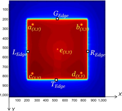
In this study, five tungsten carbide ball bearings with 4.8 mm diameter were used as phantom. Four of the ball bearings were embedded in a 2 mm thick solid water slab and were fixed to the gantry head. The fifth was positioned at nominal linac isocenter based on room lasers. It was fixed to the treatment couch top with a plastic rod, while the treatment couch and collimator were both set at zero angle.
The 6 MV beams were used for irradiations with 20.0×20.0 cm2 MLC-defined fields at zero collimator angle. EPID images were exported in digital imaging and communications in medicine (DICOM) format with 10 MU irradiations per image at 10° intervals, providing 37 images for an entire gantry rotation. Each set of measurements were performed three times to yield the reproducibility of results. The test was performed in both clockwise (CW) and counter-clockwise (CCW) directions to check any possible effects. The nominal source-to-detector distance (SDD) was 150 cm. The data acquired at zero gantry angle were taken as reference to determine relative deviations at other angles, since reference machine data acquisition and calibrations are performed at zero gantry angle. All results were scaled back to the isocenter plane, except for the changes in SDD during arc. Data analysis and algorithm development were performed using MATLAB programming language and software (The MathWorks Inc., MA, USA).
Analysis methods
A sample snapshot is shown in . In this section, details of the analysis method for characterization of each component are explained separately. A single set of 37 images acquired with a whole gantry rotation provides data for all of the components under investigation, and the software needs to be run only once to load all images and output the entire set of results. The algorithm for determination of the center of each ball bearing and the field edges has been explained elsewhere.Citation7,Citation9,Citation16
Figure 1 Illustration of an image acquired using the Siemens system.
Abbreviation: SDD, source-to-detector distance.
The elapsed time for the procedure is ~27 minutes, including ~6 minutes for the setup, ~20 minutes for acquiring images and exporting them, and ~1 minute for the processing of data using a computer with 4.00 GB RAM and 2.60 GHz CPU.
EPID sag
To find the EPID sag, the center of ball bearing (e) positioned at the nominal isocenter is determined in each image and is compared with its position in the image acquired at zero gantry angle. Calculations are based on EquationEquations 1(1) and Equation2
(2) .
(1)
(2) where (EPID SagX)θ and (EPID SagY)θ are the EPID sag in the X (cross-plane) and Y (in-plane) directions at θ gantry angle;
. and
are the positions of the ball bearing (e) in X and Y directions at θ gantry angle. (A cos θ) and (B sin θ) are applied to correct for displacements of the ball bearing (e) due to laser misalignments. These misalignments introduce a simple periodic function into the geometric location of the marker image on the EPID during a whole gantry rotation, since the gantry moves in a circular path. A and B are constants (Fourier coefficients), and θ is the gantry angle in radians. More details on these corrections can be found in another publication.Citation9 The EPID sag values at zero gantry angle are denoted as (EPID SagX)0 and (EPID SagY)0.
Gantry sag
To measure the gantry sag values, positions of the four ball bearings fixed to the gantry head (a, b, c, and d) are averaged in both directions (X and Y) at each gantry angle. These values represent a combination of the EPID sag and the gantry wobble. To determine the net gantry sag, the values for EPID sag are subtracted from the EPID + gantry sag (EquationEquations 3(3) and Equation4
(4) ).
(3)
(4) where aX, bX, cX, dXθ and aY, bY, cY, dYθ are the averages of X and Y positions of the four ball bearings. These parameters are measured at each gantry angle.
Changes in SDD
The change in the SDD as a result of gantry rotation is calculated using EquationEquation 5(5) . This effect is a result of both EPID sag and gantry wobble along the radiation beam direction.
(5) where SDD0 is the SDD at zero gantry angle as read out from the DICOM header; aX, cXθ and bX, dXθ are the averaged positions of ball bearings (a) and (c), and (b) and (d), respectively, at gantry angle θ. These parameters are measured at each gantry angle.
EPID and collimator skewness
A combination of EPID and collimator (gantry head) skewness is determined at every gantry angle from EquationEquation 6(6) . The method is based on a geometrical calculation that uses the position of one ball bearing pair from the four attached to the gantry head ([a] and [b] or [c] and [d]) at zero and θ gantry angles.
(6) where ψθ is the combined skewness of the EPID and collimator in degrees. It is worthwhile to mention that skewness (yaw) is defined as the rotation in the EPID/collimator plane. The combined skewness of the EPID and collimator has been investigated, since the software cannot differentiate between the causes of rotations. The positive direction is the CW rotation.
EPID tilt
The EPID tilt in the in-plane (pitch) and cross-plane (roll) are determined using EquationEquations 7(7) and Equation8
(8) , respectively. To find these values, only the four ball bearings fixed to the gantry head are considered.
(7)
(8)
These equations are based on simple geometric relations using the distances between the ball bearing pairs (a and b) and (c and d) at various gantry angles.
The indices G, T, L, and R denote the gun, target, left, and right directions, respectively. The above values are compared with the tilt at zero gantry angle that was selected as reference.
Sag in the leaf bank assembly
The sag in the MLC bank assembly corresponding to each gantry angle in the G, T, L, and R directions in the in-plane and cross-plane directions are quantified using EquationEquations 9(9) –Equation12
(12) .
(9)
(10)
(11)
(12) where
, etc, represent the positions of four field edges at each gantry angle.
and
, are based on the averaged leaf positions in each bank.
Results
For each of the results sets, a graph is presented that contains the results for all tested linacs using 6 MV beams in CW direction (results ±1 standard deviation [SD]). In addition, a table has been prepared for the sets of results for each of the investigated components. Tables include the average range of deviations (±1 SD), largest range of deviations, worst reproducibility (largest SD among different linacs – three sets of measurements on each), and finally largest root mean square deviations (RMSD) between the data sets acquired in CW vs CCW gantry rotation.
EPID sag
Results of EPID sag measurements in all linacs are given in and . The range of variations is considered as the difference between maximum and minimum values in the data for each linac. The largest range of variations among all linacs is given in for each direction.
Figure 2 Comparison of EPID sag measurement results for the tested Siemens linacs in (A) cross-plane and (B) in-plane directions.
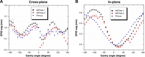
Table 1 Comparison of some statistical characteristics in EPID sag among the tested linacs
The largest RMSD across the compared sets of data in all linacs are also listed in . (For instance, the RMSD between the CW and CCW gantry rotations is calculated for each machine and the largest RMSD among all linacs is reported.)
The values of EPID sag were <0.2 mm in the cross-plane direction in all linacs, while larger deviations were observed in the in-plane direction (0.7 mm). However, they were all within 2 mm, which is the accepted criterion for nonstereotactic linacs, based on the AAPM TG 142 report.Citation34
Gantry sag
Measurement results of gantry sag at various gantry angles for all linacs are given in and .
Figure 3 Comparison of gantry sag measurement results for the tested Siemens linacs in (A) cross-plane and (B) in-plane directions.
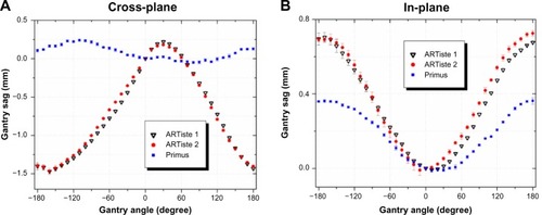
Table 2 Comparison of some statistical characteristics in gantry sag in the tested linacs
As shown in , two linacs moved further than the 1 mm acceptance criterion for gantry sag.Citation34
Changes in SDD
Results of the measured changes in the SDD in the beam direction are shown in and listed in .
Figure 4 Comparison of the results of changes in SDD for the tested Siemens linacs.
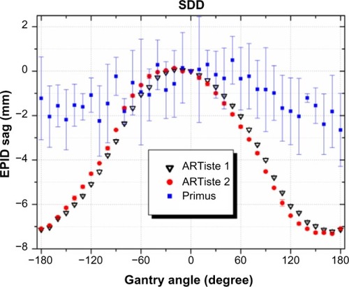
Table 3 Comparison of some statistical characteristics in SDD changes for the tested linacs
shows that the changes in SDD of two tested linacs were greater than the 5 mm accepted criterion.Citation34 The largest change in the SDD was 7.5 mm, which results in 0.40% image magnification and corresponds to 0.16% change in dose when the EPID is used for absolute dosimetry.
EPID and collimator skewness
Results of measurements of the EPID and collimator skewness for all linacs are compared in and .
Figure 5 Comparison of the measured skewness in EPID and collimator for the tested Siemens linacs.
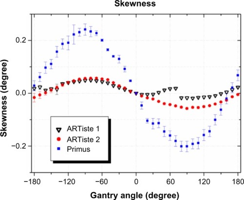
Table 4 Comparison of some statistical characteristics in EPID and collimator skewness for the tested linacs
The EPID and collimator skewness values were below 0.4° for all tested linacs.
EPID tilt
Results of the EPID tilt measurements for all linacs are given in and .
Figure 6 Comparison of EPID tilt measurement results for the tested Siemens linacs in (A) the cross-plane and (B) the in-plane directions.
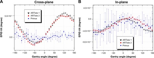
Table 5 Comparison of some statistical characteristics in EPID tilt for the tested linacs
The detected EPID tilt values were negligible for all tested linacs. The scale of graphs in indicates the precision of the algorithm.
Sag in the leaf bank assembly
and show the measured sag patterns in the leaf bank assembly of the tested linacs in four directions.
Figure 7 Comparison of the measured sag values in leaf bank assemblies of the tested Siemens linacs for (A) gun side, (B) target side, (C) left side, and (D) right side.
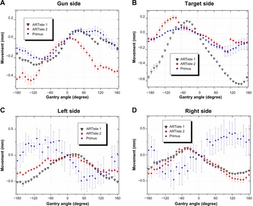
Table 6 Comparison of some statistical characteristics in the measured sag values in leaf bank assemblies of the tested linacs
The range of sag in the leaf bank assemblies, which produces systematic error, was <0.7 mm in all directions over all tested linacs. Although the acceptance limit for deviations in MLC positioning is within 1 mm,Citation34 it has been shown that some complex clinical techniques may be sensitive to smaller variations in MLC leaf positioning.Citation18
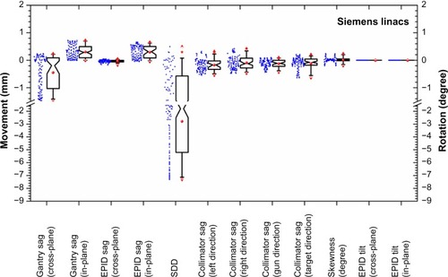
Summary of results
A summary of the results obtained in 6 MV beams with CW gantry rotations is shown in a box plot in . This graph illustrates the statistical distributions of data points across the entire sets of data acquired on all tested machines.
Figure 8 The data points acquired in 6 MV beams with gantry rotations in the clockwise direction are illustrated in a box plot.
Abbreviations: EPID, electronic portal imaging device; CI, confidence interval; SDD, source-to-detector distance.
Discussion
A comprehensive study was performed on three Siemens linacs to investigate the mechanical stability of their gantries, MLC leaf bank assemblies, and megavoltage imagers at different gantry angles. This is meant to provide a measure of the stability of these systems during delivery of modern radiotherapy treatments in arcs. All aforementioned linac components are affected by gravitational force during gantry rotation due to their structural imperfections. Information on the impact of rotation on these systems will assist in delivery of more accurate treatments by improving pretreatment verification of complex plans, real-time tumor tracking, real-time dosimetry, and linac quality assurance processes.
In this study, a simple measurement method is proposed to simultaneously quantify the gantry, leaf bank, and EPID movements at a number of gantry angles. A simple phantom was designed with just five metallic markers in the beam, and a large amount of information on the system characteristics were extracted from 37 EPID images. The analyses were performed using in-house-developed software, which proved to be accurate, robust, and fast. The set of EPID images taken at different gantry angles are analyzed in one execution of the software, and the required geometric parameters are automatically produced.
The EPID sag measurement results over a range of machines showed that on average, the EPIDs moved by 0.2 mm in the cross-plane and by 0.7 mm in the in-plane directions. The difference between deviations in the two directions was attributed to the structure of the EPID support system with the middle arm providing more freedom of movement along the in-plane direction. This was attributed to the complexity of the mechanical structure of the system that has many junctions and several sliding or bolted mechanical parts. The EPID sag values and patterns in both the cross-plane and in-plane directions were similar to Varian machines.Citation4,Citation9,Citation19
If a Siemens EPID shows large values of sag, it would be advisable to check the detector arm fixings, check the detector panel movements and brakes, check for loosened carriage bolts, and finally replace the axis motor or gearboxes.
The average range of gantry sag values was 0.6 mm in the in-plane and 1.2 mm in the cross-plane directions ().
Varian Medical Systems has recently introduced a phantom and method as a tool for geometric calibration of imager arms and tune its alignment in TrueBeam linacs. The phantom (IsoCal) includes 16 tungsten carbide ball bearings arranged in a certain projection pattern unique for each gantry angle and an aluminum partial transmission plate attached to the gantry head with a hole in the middle.Citation35,Citation36 However, this system has serious limitations such as need for proper alignment of the phantom for accurate results, dependence on the accuracy of room lasers for phantom alignment, need for accurate manufacture of the phantom, and not being able to cover the whole 360° rotation of gantry. In addition, the shadow of the aluminum plate can introduce errors in the analysis, and if the variation of arm trajectories is not smooth, the accuracy of algorithm will be affected.Citation10
Gantry sag values were found to be smaller for the tested Primus linac in both the cross-plane and in-plane directions compared with the ARTiste model. This was attributed to the reinforcement of the gantry assembly on the stand using cross bars and addition of a strong torque limiter (overload clutch) in this modified linac in addition to an extra 90 kg weight imposed to the gantry head. In contrast to the ARTiste machines, the sag pattern for the Primus linac was similar to Varian systems in both directions.Citation9,Citation19
Siemens has over time modified the gantry of their linacs. The Primus linac investigated in this work was delivered with a modified gantry with better isocentric performance. Officially, the modified gantry was introduced later than the tested Primus. However, the gantry could have been with an intermediate modified version; even its structure seems to be identical to the drawings of the modified gantry. Therefore, the gantries of the linacs in this work might be slightly different and have different performance.
If large gantry sag values are detected in a Siemens linac, it may indicate tension in the gantry chain or in the fixing clamps of the gantry base. Examining all sub-assemblies in the gantry is recommended.
The change in SDD as a result of gantry rotation was 6.0 mm on average. The SDD change in Elekta EPIDs has previously been reported to be around 9.2 mmCitation37 by two independent methods. These values are reported for Varian machines equipped with R-type arms, which have shown changes up to 13 mm.Citation21,Citation38 Checking the vertical axis motor, belt drives, and encoders are recommended to determine the cause of any possible out-of-tolerance movements.
The values found for EPID and collimator skewness and for EPID tilt were <1°. Large EPID tilt and skew values may require checking of the tilt axis motor, tilt axis belt drive, and tilt axis secondary encoder. Recalibration of the tilt, vertical and longitudinal position, may be necessary.
In Siemens linacs, the leaf bank assembly and the drive unit system are mounted on a drive leaf guide frame. This frame can move under the influence of gravity; therefore, although displacements of each individual leaf can be accurately detected, the monitoring system is unable to recognize the sag in the MLC leaf bank assembly.
The average sag in the leaf bank assemblies of the tested Siemens linacs were around 0.5 mm in all directions and <1 mm for largest range of movement. Smaller sag values were found for Varian linacs, which were reported as 0.15 mm on the gun side, 0.05 mm on the target side, 0.52 mm on the left side, and 0.55 mm on the right side.Citation16
Large sag in the MLC drive unit may be due to loosened assembly frame screws or dislodged leaf ball bearings. Installation of new MLC bearings may be required. It is better to check the drive unit for its full engagement with the shaft assembly.
According to –, changing the direction of gantry rotation (CW or CCW) did not affect the results, and the largest detected differences were <0.5 mm in all of the three investigated machines.
All experiments were highly reproducible, and the largest SD between three sets of similar setups (ie, worst reproducibility) was <0.3 mm for all of the measured parameters except for changes in SDD, which was 2.3 mm in the Primus linac.
The behavior of the Siemens linac components investigated in this study was generally consistent and followed a similar pattern. The main exception was the gantry sag in the cross-plane direction, which was most likely to be the result of reinforcement of the gantry assembly in the Primus linac.
A similar correction as the method explained by Rowshanfarzad et alCitation9 is applicable to the results for Siemens machines.
Conclusion
With the emergence of complex technology in the modern radiotherapy, reliable methods are required to ensure accurate delivery of treatments. In this work, a large amount of information on characteristics of Siemens linac components at different gantry angles were provided using EPID images acquired with five metallic markers in the beam. A fast and accurate software package was developed for the analysis of images.
Acknowledgments
The authors gratefully acknowledge Ms Katalin Szep from Siemens Customer Solutions, Erlangen, Germany, for helpful discussions and detailed information on the Siemens linac mechanical constructions, and Mr Terje Pedersen, Radiofysisk Laboratorium, Odense University Hospital, Odense, Denmark, for a stand-alone solution of the Mosaiq verification system to allow EPID image acquisition on the Siemens Primus linac. This work was partly supported by the WA Department of Health Merit Award.
Disclosure
The authors declare that they have no competing interests in this work.
References
- WinklerPBergmannHStuecklschweigerGGussHIntroducing a system for automated control of rotation axes, collimator and laser adjustment for a medical linear acceleratorPhys Med Biol2003481123113212765326
- RoscaFLorenzFHackerFLChinLMRamakrishnaNZygmanskiPAn MLC-based linac QA procedure for the characterization of radiation isocenter and room lasers’ positionMed Phys20063361780178716872085
- DuWGaoSMeasuring the wobble of radiation field centers during gantry rotation and collimator movement on a linear acceleratorMed Phys2011384575457821928629
- DuWGaoSWangXKudchadkerRJQuantifying the gantry sag on linear accelerators and introducing an MLC-based compensation strategyMed Phys20123942156216222482636
- RiisHLZimmermannSJHjelm-HansenMGantry and isocenter displacements of a linear accelerator caused by an add-on micromultileaf collimatorMed Phys201340303170723464302
- RowshanfarzadPSabetMO’ConnorDJGreerPBIsocentre verification for linac-based stereotactic radiation therapy: review of principles and techniquesJ Appl Clin Med Phys2011124185195
- RowshanfarzadPSabetMO’ConnorDJGreerPBVerification of the linac isocentre for stereotactic radiosurgery using cine-EPID imaging and arc deliveryMed Phys20113873963397021858993
- WineyBSharpGBussièreMA fast double template convolution isocenter evaluation algorithm with subpixel accuracyMed Phys20113822322721361190
- RowshanfarzadPSabetMO’ConnorDJMcCowanPMMcCurdyBMCGreerPBDetection and correction for EPID and gantry sag during arc delivery using cine EPID imagingMed Phys201239262363522320771
- LiuBAdamsonJRodriguesAZhouFYinFFWuQA novel technique for VMAT QA with EPID in cine mode on a varian TrueBeam linacPhys Med Biol2013586683670024018655
- PerksJLehmannJNarayanSUtilization of image-guided radiation therapy equipment to enhance stereotactic body radiation therapy commissioningRadiosurgery20107397402
- OldingTGarciaLAlexanderKSchreinerLJJoshiCStereotactic body radiation therapy delivery validationJ Phys2013444012073
- Mamalui-HunterMLiHLowDALinac mechanic QA using a cylindrical phantomPhys Med Biol2008535139514918723927
- JinGHZhuJHChenLXGantry angle-dependent correction of dose detection error due to panel position displacement in IMRT dose verification using EPIDsPhys Med20143020921423786885
- MubataCDChildsPBidmeadAMA quality assurance procedure for the varian multi-leaf collimatorPhys Med Biol1997424234319044424
- RowshanfarzadPSabetMO’ConnorDJGreerPBInvestigation of the sag in linac secondary collimator and MLC carriage during arc deliveriesPhys Med Biol20125712N209N22422643340
- AgnewAAgnewCEGrattanMWHounsellARMcGarryCKMonitoring daily MLC positional errors using trajectory log files and EPID measurements for IMRT and VMAT deliveriesPhys Med Biol2014599N49N6324732210
- RangelADunscombePTolerances on MLC leaf position accuracy for IMRT delivery with a dynamic MLCMed Phys2009363304330919673226
- RowshanfarzadPMcGarryCKBarnesMPSabetMEbertMAn EPID-based method for comprehensive verification of gantry, EPID and the MLC carriage positional accuracy in varian linacs during arc treatmentsRadiat Oncol2014924925424471
- RowshanfarzadPRiisHLZimmermannSJEbertMAA comprehensive study of the mechanical performance of gantry, EPID and the MLC assembly in Elekta linacs during gantry rotationBr J Radiol2015882014058125906294
- AnsbacherWThree-dimensional portal image-based dose reconstruction in a virtual phantom for rapid evaluation of IMRT plansMed Phys2006333369338217022233
- McCurdyBMCGreerPBDosimetric properties of an amorphous-silicon EPID used in continuous acquisition mode for application to dynamic and arc IMRTMed Phys2009363028303919673202
- MansARemeijerPOlaciregui-RuizI3D dosimetric verification of volumetric-modulated arc therapy by portal dosimetryRadiother Oncol20109418118720089323
- GrattanMWMcGarryCKMechanical characterization of the varian exact-arm and R-arm support systems for eight aS500 electronic portal imaging devicesMed Phys20103741707171320443491
- BaileyDWKumaraswamyLBakhtiariMMalhotraHKPodgorsakMBEPID dosimetry for pretreatment quality assurance with two commercial systemsJ Appl Clin Med Phys20121328299
- CyriacSMusthafaMMGanapathi RamanRAbdul HaneefaKHridyaVTPretreatment patient specific quality assurance and gamma index variation study in gantry dependent EPID positions for IMRT prostate treatmentsJ Radiother20142014325057
- FuangrodTWoodruffHVan UytvenEA system for EPID-based real-time treatment delivery verification during dynamic IMRT treatmentMed Phys201340111
- WoodruffHWFuangrodTRowshanfarzadPMcCurdyBMCGreerPBGantry-angle resolved VMAT pretreatment verification using EPID image predictionMed Phys201340808171523927312
- LiuWWiersmaRDMaoWLuxtonGXingLReal-time 3D internal marker tracking during arc radiotherapy by the use of combined MV–kV imagingPhys Med Biol2008537197721319043177
- Han-OhSYiBYLermaFBermanBLGuiMYuCVerification of MLC based real-time tumor tracking using an electronic portal imaging deviceMed Phys20103762435244020632553
- NgJBoothJPoulsenPKilovoltage intrafraction monitoring for prostate intensity modulated arc therapy: first clinical resultsInt J Radiat Oncol Biol Phys2012845e655e66122975613
- SillanpaaJChangJMagerasGDevelopments in megavoltage cone beam CT with an amorphous silicon EPID: reduction of exposure and synchronization with respiratory gatingMed Phys20053281982915839355
- FuangrodTWoodruffHCRowshanfarzadPO’ConnorDJMiddletonRHGreerPBAn independent system for real-time dynamic multileaf collimation trajectory verification using EPIDPhys Med Biol201459618124334552
- KleinEEHanleyJBayouthJTask Group 142, American Association of Physicists in MedicineTask group 142 report: quality assurance of medical acceleratorsMed Phys20093694197421219810494
- Varian Medical SystemsTrueBeamTM, TrueBeamSTxTM, Technical reference guide (Version 1.6 Volume 2: Imaging; Docu ID: B501671R01, RevisionD)Varian Medical Systems, IncSwitzerland2011205207
- GaoSDuWBalterPMunroPJeungAEvaluation of IsoCal geometric calibration system for varian linacs equipped with on-board imager and electronic portal imaging device imaging systemsJ Appl Clin Med Phys2014153164181
- ClarkeMFBudgellGJUse of an amorphous silicon EPID for measuring MLC calibration at varying gantry anglePhys Med Biol200853247348518185000
- ChinPWLewisDGSpeziECorrection for dose-response variations in a scanning liquid ion chamber EPID as a function of linac gantry anglePhys Med Biol2004498N93N10315152695