
Abstract
Reliable detection of pacemaker pulses is getting more and more important in electrocardiography (ECG) diagnosis. Many studies recommend ECG amplifiers with higher bandwidth to prevent errors. In the past, few pilot studies showed that analysis of pacemaker pulses waveform can enhance diagnosis (eg, lead failure and fractured wire), but they were carried out with inadequate instrumentations for clinical practice. Typically, pacemaker pulses last hundreds of microseconds, edges of pulses elapse in few microseconds, and amplitude may exhibit large variations from few millivolts to volts. Pulse waveforms change often and depend on pacemaker type and programming. A simple, biopotential amplifier made of a few off-the-shelf components is proposed. The circuit fulfills specifications for biopotential amplifiers and offers a large bandwidth (~1 MHz). Therefore, it is able to accurately record time course of pacemaker pulses and allows highly accurate pulse detection and timing. Signals can be easily displayed and acquired by means of a standard, battery-powered oscilloscope. Pacemaker pulse vectorcardiography can be obtained by using two or more, wideband channels. Some exemplificative waveforms recorded during patient’s periodic medical examination are reported. The proposed circuit offers simultaneous conventional ECG signal as an additional output.
Introduction
The number of patients undergoing implantation of permanent pacemakers is continuously increasing.Citation1,Citation2 Therefore, the number of electrocardiography (ECG) recordings that contain pacemaker signals is growing continuously.
Common ECG devices are not always able to provide a reliable detection of pacemaker pulses (mainly because of their limited frequency response and slow sampling rate). Indeed, one of the most common errors in ECG interpretation concerns misrecognition of pacemaker spikes.Citation3–Citation5 This is because the pulses have very short durations (often <0.5 ms) compared to the ordinary sampling intervals and, sometimes, even very small amplitudes (eg, few millivolts). Nevertheless, reliable detection of occurrence and timing of pacing pulses is fundamental for proper diagnosis, also considering recent evolutions of cardiac electrical therapy (eg, cardiac resynchronization therapyCitation6). Hence, the need of more adequate instrumentation has been recognized by medical associationsCitation7 and technical standard organizations.Citation8–Citation10 Essentially, use of ECG amplifiers with wider bandwidth and higher sampling frequency is recommended.Citation3–Citation5,Citation11 Indeed, since pacemaker pulses have very short duration, the higher the bandwidth of ECG amplifier, the better is the detection and timing of pulses.
In the past, analysis of pulse waveform was proposed in order to ensure more accurate examination of pacemaker implants.Citation12–Citation14 These old prototype systems relied on a direct electrical connection between patient’s skin electrodes and an oscilloscope. Although the use of an oscilloscope fulfils the wide bandwidth requirement, it is not compliant with patient’s electrical safety issues (eg, general standards for medical electrical equipmentCitation15) and does not allow reliable capture of small amplitude pacemaker spikes. Display of pacemaker pulse waveform proved useful to identify faults or impending failure, such as lead failure, fractured wire, and changes in the electrical property of electrode–tissue interface.Citation16,Citation17
Analysis of pulse waveform provides an accurate measurement of concise parameters (eg, pulse duration); moreover, it helps to detect lead failure, discriminate between fractured wire and ruptured insulation, and evaluate changes in the electrode/tissue interface and electrode impedance and of output circuitry problems.
A simple, wideband (1 MHz) ECG front-end circuit that allows recording pacemaker pulse waveforms is presented. The circuit was tested in a clinical setting, and some recordings are shown for illustrative purposes.
Methods and results
Most bioelectric amplifiers use instrumentation amplifier to provide high common mode rejection ratio to record electric potentials from patient’s body. In general, an integrated instrumentation amplifier (eg, single chip embedding closely matched laser-trimmed resistors and, therefore, offering excellent common mode rejection ratio) is preferable with respect to assembly of distinct components (eg, Op Amps and resistors), which otherwise requires calibration to achieve adequate common mode rejection ratio. Unfortunately, the vast majority of integrated instrumentation amplifiers operate in a limited frequency range (eg, from zero to few kilohertz) and are adequate to collect most common physiological signals but are not suitable to record pacemaker pulses. Very few integrated instrumentation amplifiers, such as INA217 and AD8421, provide satisfactory bandwidth specification for this purpose. The INA217 by Texas Instruments (Dallas, TX, USA) was selected for the proposed circuit. The schematic diagram of the circuit is illustrated in .
Figure 1 Schematic of the wideband biopotential amplifier.
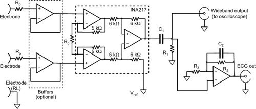
The circuit is powered by a dual tension of ±9 V provided by two disposable batteries (not shown in ). The amplification of the first stage was kept small (ie, 10 V/V; Rg=180 kΩ) in order to prevent the amplifier saturation,Citation18 by considering the relatively high level of power line interference, electrode half-cell potentials, and also possible high amplitude of pacemaker pulses. The 10 V/V gain ensures a bandwidth from 0 Hz to, at least, 1 MHz. The input impedance offered by the INA217 is 60 MΩ, which is compliant with the ANSI/AAMI EC11 standard and therefore allows direct connection to patient’s electrodes. However, two simple op-amp-based unity-gain buffer amplifiers (eg, TL072) can be optionally added before instrumentation amplifier inputs to achieve much higher input impedances. However, it is wise to insert protection resistors in series with electrodes (Rp=1.1 kΩ in ) so as to limit patient’s currents, even in case of failure. At the instrumentation amplifier output, a passive, high-pass filter (C1=4.7 µF, R1=3.3 MΩ: cut-off frequency <0.05 Hz) blocks any offset and low frequencies of no clinical interest. After high-pass filtration, the signal is fed directly into a standard, battery-powered, oscilloscope to visualize pacemaker pulses.
A simultaneous, standard ECG derivation is provided by the active, low-pass filter (C2=10 nF, R2=100 kΩ, R3=1 kΩ), which limits the bandwidth to 150 Hz and provides an overall gain of 1,000 V/V. The entire circuit can be replicated to obtain multiple ECG leads. Assembled prototypes included a maximum of two parallel amplifiers (ie, standard ECG lead I and II), enough to obtain pacemaker vectorcardiogram on frontal plane.
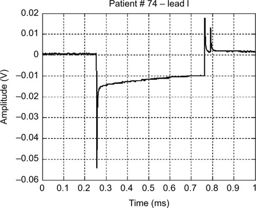
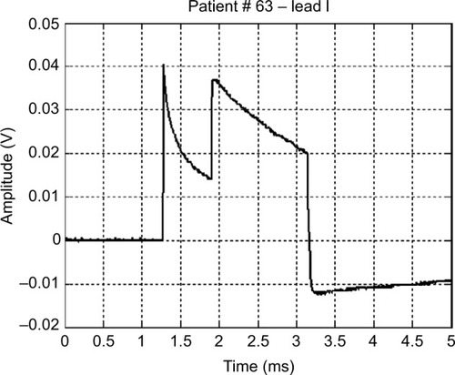
The prototype systems were used, as additional diagnostic support, during periodic follow-up of pacemaker patients. As example of typical waveforms, and show pulses generated by unipolar leads, while shows a waveform generated by a bipolar lead (much smaller in amplitude). presents the frontal plane vectorcardiogram obtained combining lead I and lead II () data: the orientation of pulse vector corresponds to the direction of the line connecting the electrode and the pacemaker casing (this pacemaker device was implanted subcutaneously in the infraclavicular region, and the pacing electrode was placed in the right ventricle apex). From those figures, the characteristic shape of a pacemaker pulse can be clearly noted. It appears as the exponential discharge of the output capacitor into the lead load, limited to the programmed duration of the pulse. The leading and trailing edges of the pacemaker pulses usually last few microseconds (eg, those steepest 2–3 µs). Amplitudes of pulses change during the various phases of respiratory cycle (because of chest displacements and changes in thoracic impedance), similar to amplitudes of QRS in ECG recording.
Figure 2 Lead I and lead II pacemaker waveform and the corresponding vectorcardiogram
Abbreviation: ECG, electrocardiography.
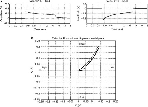
Figure 3 An example of a monopolar pacemaker waveform recorded from ECG lead I.
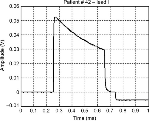
Figure 4 An example of a bipolar pacemaker waveform recorded from ECG lead I.
shows a waveform occasionally produced by a pacemaker with a defective output circuit, probably a bad electrical contact in the electrocatheter. The occurrence of this waveform type was occasional and, in some cases, associated with missed cardiac stimulation. After recording this anomaly, the patient was subjected to further medical examinations and finally underwent surgery to replace the whole implant.
Figure 5 Waveform of a monopolar pacemaker with a defective output circuit.
Conclusion
A biopotential amplifier with a bandwidth of ~1 MHz is proposed. The amplifier fulfils specifications suggested by international standard for electrocardiographic devices. The circuit is based on an integrated instrumentation amplifier (INA217) and has no need of calibration. Therefore, it can be simply embedded in various instrumentations that require highly accurate pacemaker pulse detection and timing. The wide bandwidth of the amplifier allows recording of accurate pacemaker pulse waveforms and also reproducing the fast-varying edges of pulses. Vectorcardiography of pacemaker pulses can be obtained by combining two or more amplifiers. In addition, the proposed circuit offers simultaneous conventional ECG signal as additional output.
This simple circuit can find application in equipment for the display and analysis of the waveforms produced by pacemaker and also where a precise timing of the pulses is required (eg, in biventricular pacing). It is also possible to precisely estimate the duration of each pulse, intertime between two pulses in magnetic mode (related to the state of charge of the battery), etc, of any pacemaker type, irrespective of availability of the specific programmer supplied by each manufacturer. In addition, analysis of pacemaker pulse droop (the exponential decay after the leading edge) can potentially provide interesting information about the lead impedance.Citation19–Citation21 Recently, some studiesCitation22,Citation23 renewed the interest in the examination of pacemaker waveforms and have emphasized their potential to add new and detailed diagnostic information.Citation24 The simplicity of realization of the proposed circuit and its possible use in clinical trials can promote the deepening of particular issues related to periodical monitoring of pacemaker implants. The circuit can be embedded in instrumentation for continuous monitoring of the ECG, such as Cardiac Holter monitors and other devices.Citation25
Disclosure
The authors report no conflicts of interest in this work.
References
- UslanDZTleyjehIMBaddourLMTemporal trends in permanent pacemaker implantation: a population-based studyAm Heart J2008155589690318440339
- Writing Group MembersRogerVLGoASAmerican Heart Association Statistics Committee and Stroke Statistics SubcommitteeHeart disease and stroke statistics 2012 update: a report from the American heart associationCirculation20121251e2e22022179539
- GuglinMEDatwaniNElectrocardiograms with pacemakers: accuracy of computer readingJ Electrocardiol200740214414616919672
- PoonKOkinPMKligfieldPDiagnostic performance of a computer-based ECG rhythm algorithmJ Electrocardiol200538323523816003708
- GulginMEThataiDCommon errors in computer electrocardiogram interpretationInt J Cardiol2006106223223716321696
- BaroldSSMichaelCGBengtHAnneBCDiagnostic value of the 12-lead electrocardiogram during conventional and biventricular pacing for cardiac resynchronizationCardiol Clin2006244719016939837
- KligfieldPGettesLSBaileyJJAmerican Heart Association Electrocardiography and Arrhythmias Committee, Council on Clinical CardiologyAmerican College of Cardiology FoundationHeart Rhythm SocietyRecommendations for the standardization and interpretation of the electrocardiogram: part I: the electrocardiogram and its technology a scientific statement from the American Heart Association Electrocardiography and Arrhythmias Committee, Council on Clinical Cardiology; the American College of Cardiology Foundation; and the Heart Rhythm Society endorsed by the International Society for Computerized ElectrocardiologyJ Am Coll Cardiol200749101109112717349896
- American National Standard ANSI/AAMI EC11Diagnostic Electrocardiographic DevicesArlington, VAAssociation for the Advancement of Medical Instrumentation (AAMI)2007
- International Standard IEC 60601-2-51Medical Electrical Equipment Part 2–51: Particular Requirements for Safety Including Essential Performance, of Recording and Analyzing Single Channel and Multichannel ElectrocardiographsGenevaInternational Electrotechnical Commission (IEC)2003
- American National Standard ANSI/AAMI EC13Cardiac Monitors, Heart Rate Meters, and AlarmsArlington, VAAssociation for the Advancement of Medical Instrumentation (AAMI)2007
- RickeADSwirynSBauernfeindRAConnerJAYoungBRowlandsonGIImproved pacemaker pulse detection: clinical evaluation of a new high-bandwidth electrocardiographic systemJ Electrocardiol201144226527421146832
- GrendahlHRegistration of pacemaker-induced skin potentials in the routine control of implanted pacemakersScand J Clin Lab Invest19692432512595375741
- GreenGDForbesWBainWHShawGBKenmureACDetection of faults in implanted cardiac pacemakersBr Heart J19693167077105358151
- DaviesJGSiddonsHThe detection of impending failure in implanted pacemakersThorax196924174775763513
- International Standard IEC 60601-1Medical Electrical Equipment – Part 1: General Requirements for Basic Safety and Essential PerformanceGenevaInternational Electrotechnical Commission (IEC)2012
- SowtonEGrayKClinical testing of implanted pacemakersThorax19712621451545576529
- HepburnFDiscriminating between types of pacemaker lead failureJ Med Eng Technol197823130135
- GargiuloGBifulcoPCesarelliMAn ultra-high input impedance ECG amplifier for long-term monitoring of athletesMed Dev (Auckl)2010319
- Anelli-MontiMMächlerHOberwalderOKnezIDacarDRiglerBLead stability in long-term follow-up of bipolar leadsWien Med Wochenschr200015019–2141441811132435
- DorwarthUFreyBDugasMTransvenous defibrillation leads: high incidence of failure during long-term follow-upJ Cardiovasc Electrophysiol2003141384312625608
- LuriaDGliksonMBradyPAPredictors and mode of detection of transvenous lead malfunction in implantable defibrillatorsAm J Cardiol200187790190411274950
- BartschCIrnichWRisseMJungeMWeilerGPostmortem in situ diagnosis of pacemakers and electrodes to detect dysfunctionLeg Med (Tokyo)20035suppl 1S397S40012935642
- BartschCIrnichWJungeMStertmannWARisseMWeilerGPost-mortem evaluation of 415 pacemakers: in situ measurements and bench testsEuropace20057217518015763534
- TannenbergMSepsiMMeasurement and significance of pacemaker pulse parametersWorld Congr Med Phys Biomed Eng2006206769772
- GargiuloGBifulcoPCesarelliMJinCMcEwanAVan SchaikAWearable dry sensors with bluetooth connection for use in remote patient monitoring systemsStud Health Technol Inform2010161576521191158