Abstract
The effect of two basic topological defects, mitosis and the Stone-Wales defect, is studied in the graphene structure. The topological rules of the curvatures due to the occurrence of the defects in different arrangements are determined. Despite the fact that the causes and the probability of these topological defects are not known today, this theoretical work studies the distortions caused by the defects geometry and stability of the graphene structure.
Introduction
It is known that pentagons built between hexagons cause the curvatures in the structures of the fullerenes and the carbon nanotube ends.Citation1,Citation2 The characteristic saddle-shaped surfaces at the junctions of the carbon nanotubes result in the heptagons built in the hexagonal structure.Citation3,Citation4 In this work the deforming effect of the pentagons and the heptagons as defects of the graphene structure is studied.
Pentagons and heptagons generally can appear in pairs in the graphene structure since the mean coordination number of the planar trivalent polygonal cell systems equals 6 according to Euler’s law.Citation5,Citation6
The effect of the Stone-Wales defect was studied on the mechanical,Citation7–Citation9 fracture,Citation10 and electronicCitation11–Citation13 properties of single-wall carbon nanotubes by different theoretical methods. In the case of the graphene structure it was observed that the Stone-Wales defect can modify the structure from planar to spatial.Citation15 The Raman spectra was calculatedCitation14 and the electronic behavior was estimated.Citation17
In this work the geometric effect of topological defects is examined to answer the question: does the graphene structure containing defects remain planar or not?
Method
Considering the topological knowledge of the planar cell systems, the two characteristic examples of their origin are:
The Stone-Wales defect is the 90° rotation of two carbon atoms with respect to the midpoint of the bond. In the Stone–Wales defect, four hexagons are changed into two pentagons and two heptagons (). The pentagons are separated by heptagons. The number of the atoms (vertexes) does not change.
Figure 1 a) The Stone–Wales defect: the gray heavy lines show the bonds before the transformation and the black heavy lines show the bonds after the transformation. b) Mitosis defect: The black heavy line show the new bond between the new atoms.
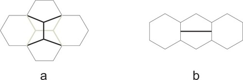
The mitosis where two pentagons originate from a given hexagon and consequently the neighboring hexagons become heptagons (). The heptagons are separated by pentagons. The number of the atoms increases by two.
Considering the possibilities for the appearing of the topological defects in the graphene structure the following arrangements can be studied:
the defect itself,
defects arranged along lines,
defects arranged in groups,
defects arranged in net.
An example for every possibility was studied in this work. A relaxation procedure was applied for the different arrangements of the topological defects. The inputs were planar patterns where the defects were constructed in the graphene structure similarly as is shown in . The goal of the relaxation procedure was to find the equilibrium state of the structure applying an energetic potential function, which is a mathematical formula for the energy of the chemical bonds. The procedure is a simplified variation of the molecular dynamic.Citation18,Citation19 The equilibrium state was reached by an iteration procedure varying the coordinates of the atoms (for example with the known mathematical gradient method) until the minimum of the energetic potential function is found. For this purpose two methods were tried out in parallel: the Desktop Molecular Modeller, which is a commercial software, and our own computer codes based on the energetic Brenner empirical potential function.Citation20 Both methods have given the same result for all examples shown in this work.
In every model shown in the following sections, an infinite structure is assumed with a periodic boundary condition.
Results and discussion
The effect of the Stone–Wales defects
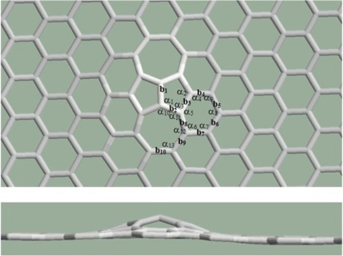
The pentagon pair separated by the heptagon pair as the result of the Stone–Wales defect occurring in the graphene structure was studied first. According to the relaxation procedures, the arrangement containing one defect remained planar (). Both the bond lengths and the angles became distorted. The rates of the distortions are summarized in . The percentile rates were computed for the data of regular pentagons, hexagons, and heptagons, for the bond length of the perfect graphene (1.42 Angström), and for the angles of the regular polygons (108° in the case of the regular pentagons, 120° in the case of the regular hexagons, and 128.57° in the case of the regular heptagons). Smaller deviations were found in the bond lengths (the largest deviation is 2.87% at b1) and larger deviations were found in the angles (the largest deviation is 10.6%: α2 inside heptagons).
Figure 2 The graphene structure containing a Stone–Wales defect remains planar.
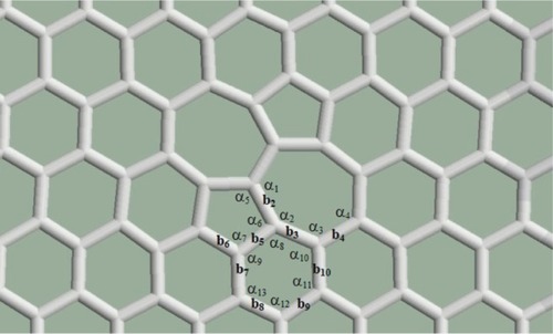
Table 1 The deformation rates for the structure shown in
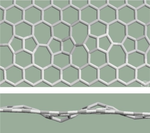
Several further examples were studied for the cases when the structure contains more defects. Pentagon–heptagon pairs are arranged in a line as shown in . The orientation of the crystal structure of the graphene is above the defect line (zigzag) rather than under the defect line (armchair). The structure remains planar according to the relaxation procedures.
Figure 3 The defects are arranged in a horizontal line.
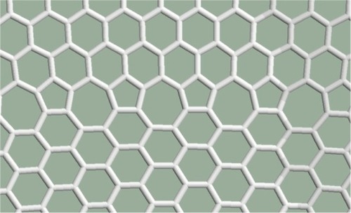
In , perfect hexagonal and pentagon–heptagon chains succeed each other. Half of the cells are not hexagonal. The structure remains planar.
Figure 4 Horizontal defect lines consisting of pentagon–heptagon pairs are constructed between the hexagonal lines.
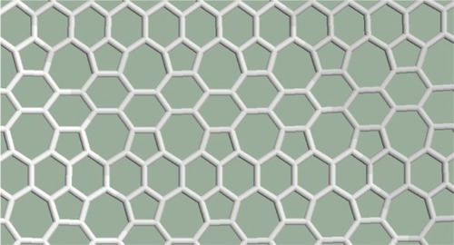
In the pentagon–heptagon pairs are arranged in a net. The nearest pentagons are separated by heptagons (or a heptagon and a hexagon) everywhere in the structure. Two-thirds of the cells are not hexagonal. The structure remains planar.
Figure 5 The pentagon–heptagon pairs are arranged in a net.
According to the relaxation procedures applied in this theoretical work, the graphene structure containing Stone–Wales defects remain planar. This should be related with the fact that this defect can be seen as a dislocation dipole. It seems that there is a cancellation in the distortions originated by the dislocations.Citation21
The effect of mitosis as topological defect
Mitosis as topological defect was studied in trivalent polygonal cell systemsCitation6 and was not studied in the graphene structure till now. This section is a theoretical consideration to determine the effect of the presence of such topological defects on the geometrical structure of the graphene.
In a first approximation, the case of mitosis as topological defect is very interesting since the relaxation procedures give a planar structure if the heptagon pair separated by the pentagon pair is studied alone (), but the structure is not planar if this defect is constrained in the graphene structure ().
Figure 6 The structure of the heptagon pair separated by the pentagon pair is planar if it is studied alone.
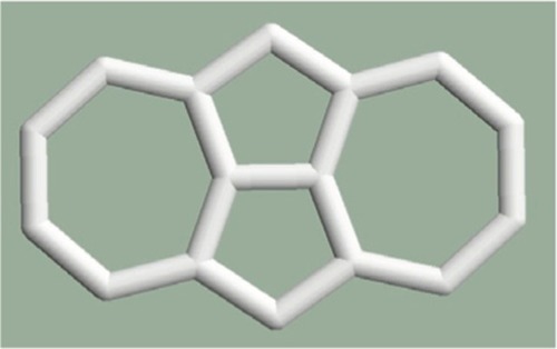
Figure 7 A curvature appears in the structure containing mitosis as topological defect. Upper: top view, lower: side view.
Both the bond lengths and the angles become distorted in the spatial structure. The rates of the distortions are summarized in . The percentile rates are computed to the bond length of the perfect graphene and to the angles of the regular polygons. It is true here again that smaller deviations were found in the bond lengths and larger deviations were found in the angles, the order of magnitude of the rates is similar to the case of the Stone–Wales defect.
Table 2 The deformation rates of bond lengths and the angles
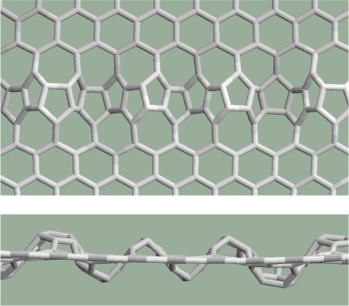
shows mitoses arranged next to each other along a line. The deformations are summarized along the line, the sum is very large, and the solution is a wavy pattern with alternating curvatures.
Figure 8 Mitoses arranged along a straight line. Upper: top view, lower: side view.
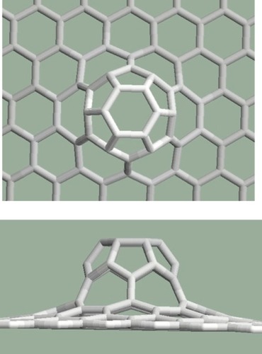
Mitoses can be arranged next to each other not only along straight lines but along curves or in groups. For example: three pentagons placed next to each other produce a larger curvature in the graphene structure than in the case of two pentagons (). It is interesting that the largest curvature arises from six mitoses arranged in a group (). In this case, six pentagons placed next to each other created a half dodecahedron, which can be the end of an armchair-type nanotube. If the six pentagons are arranged along a curve as can be seen in , the resulting structure is the end of a zigzag-type nanotube. To arrange more than six pentagons next to each other cannot be solved in a pentagon–heptagon–hexagon system.
Figure 9 Three pentagons are constructed next to each other. Upper: top view, lower: side view.
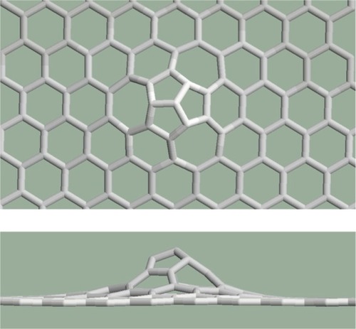
Figure 10 Six pentagons are placed next to each other in a group. Upper: top view, lower: side view.
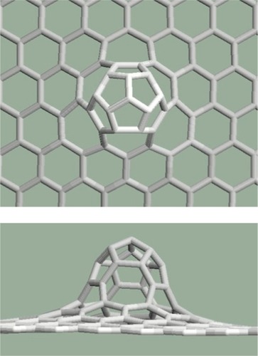
Figure 11 Six pentagons are placed next to each other along a curve. Upper: top view, lower: side view.
A significant difference between the two basic types of topological defects is that the pentagons are next to each other at the mitosis, separated in a Stone–Wales defect, and according to the presented examples that there are curvatures in the graphene structure when pentagons are placed next to each other. However, pentagons can be placed next to each other if two Stone–Wales defects are created fittingly, as shown in .
Figure 12 Stone–Wales defects placed next to each other at the pentagons cause curvature Upper: Top view, lower: side view.
Finally do pentagons and/or heptagons occur in the system alone (such patterns can be created using Stone–Wales defect series)? When a pentagon is surrounded by hexagons, a spherical surface forms and when a heptagon is surrounded by hexagons, the characteristic saddle-shaped surface forms. The example shown in contains several pentagons and heptagons, in a hexagonal environment. Relaxation procedures create a surface with alternate curvatures for this pattern.
Figure 13 Pentagons and heptagons surrounded by hexagons in the graphene structure.
The stability in the environment of the defects
To study the stability of the distorted graphene structures, the cohesive energy (the average energy of the chemical bonds: the total energy divided by the number of the bonds) was calculated for the structures shown above. The Brenner empirical potential function was used for this purpose and averages were calculated only for the closest environments of the defects (for the bonds connecting with pentagons or heptagons), this better emphasizes the effect of the defects. Cohesive energy values are summarized in .
Table 3 The cohesive energy for the environment of the defects
Cohesive energy in the environment of the defects increases several percent compared to the cohesive energy of the perfect graphene (−7.44 eV) in every case. The increase is smaller for the planar structures (–) and it is larger for the structures with curvatures (–). The more pentagons are connected to each other, the larger the decrease of stability (, –). The defects shown in have the least stability because the pentagons cause curvatures in both sides of the graphene sheet where they are connected with each other.
Conclusions
After considering the theoretical work of this study, shown in this work the following topological rules can be formulated. The graphene structure containing pentagonal and heptagonal defects does not remain planar if:
at least two pentagons can be found next to each other, or
all neighbor cells of a pentagon or a heptagon are hexagons.
With a more general topological description, curvatures can be found where:
the structure contains pentagons where the sum of the edge numbers of the nearest neighbor polygons is ≤ 31, or
it contains heptagons where the sum of the edge numbers of the nearest neighbor polygons is ≥ 42.
In the environment of the studied topological defects, the stability of the structure decreases by (the cohesive energy increases) several percent.
Acknowledgments
This work was supported by OTKA grants K 73776 and TÁMOP grants TÁMOP-4.2.1/B-09/1/KONV-2010-2013 in Hungary.
Disclosure
The author reports no conflicts of interest in relation to this work.
References
- ItohSOrdejonPDraboldDAStructure and energetics of giant fullerenes: An order-N molecular-dynamics studyPhys Rev B199653421322140
- LordiVMaSXCYaoNTowards probing pentagons on carbon nanotube tipsSurf Sci19994211–2L150L155
- BiroLPEhlichROsvathZFrom straight carbon nanotubes to Y-branched and coiled carbon nanotubesDiamond Relat Mater2002113–610815108
- LisenkovSVPonomarevaIVChernozatonskiiLABasic configuration of a single-wall carbon nanotube Y junction of D-3h symmetry: Structure and classificationPhysics of the Solid State200446815771582
- WeaireDRivierNSoap, cells and statistics-random patterns in two dimensionsContemp Phys19842515599
- MombachJCMde AlmeidaRMCIglesiasJRMitosis and growth in biological tissuesPhys Rev E Stat Phys Plasmas Fluids Relat Interdiscip Topics19934815986029960624
- PozrikidisCEffect of the Stone–Wales defect on the structure and mechanical properties of single-wall carbon nanotubes in axial stretch and twistArch Appl Mech2009792113123
- NasdalaLErnstGLengnickMRothertHFinite element analysis of carbon nanotubes with Stone–Wales defectsComput Model Eng Sci200573293304
- LuQBhattacharyaBEffect of randomly occurring Stone–Wales defects on mechanical properties of carbon nanotubes using atomistic simulationNanotechnology2005164555566
- TserpesKIPapanikosPThe effect of Stone–Wales defect on the tensile behavior and fracture of single-walled carbon nanotubesComposite Structures2007794581589
- FangXHuHFWeiJWZengHPengP[Effects of topological defects on the electronic structure and optical spectrum of single-wall carbon nanotubes.]Guang Pu Xue Yu Guang Pu Fen Xi20072771267127017944391
- EomJHLeeHImJElectronic structure of defects and quantum transport in carbon nanotubesPhysica B: Condensed Matter2006376–377710
- PachosJKManifestation of topological effects in grapheneCont Phys200950375389
- HatsugaiYFukuiTAokiHTopological aspects of grapheneEur Phys J Special Topics20071481133141
- MaJAlfeDMichaelidesAWangEStone–Wales defects in graphene and other planar sp(2)-bonded materialsPhys Rev B2009803033407
- PopovVNHenrardLLambinPResonant Raman spectra of graphene with point defectsCarbon2009471024482455
- AmaraHLatilSMeunierVLambinPCharlierJ-CScanning tunneling microscopy fingerprints of point defects in graphene: A theoretical predictionPhys Rev B20077611115423
- TerronesMBanhartFGrobertNCharlierJ-CTerronesHAjayanPMMolecular junctions by joining single-walled carbon nanotubesPhys Rev Lett2002897075505112190529
- PonomarevaIChernozatonskiiLAAndriotisANMenonMFormation pathways for single-wall carbon nanotube multiterminal junctionsNew J Phys20035119111912
- BrennerDWEmpirical potential for hydrocarbons for use in simulating the chemical vapor deposition of diamond filmsPhys Rev B1990421594589471
- SeungHSNelsonDRDefects in flexible membranes with crystalline orderPhys Rev A1988382100510189900464