
Abstract
Although total knee arthroplasty (TKA) is considered one of the most successful procedures, however, a subset of patients are unsatisfied with the results, even with the introduction of new technologies and implant designs. Radiological assessment of TKA is still considered the most prevalent imaging modality for evaluating the knee joint pre-and postoperatively. Assessment of various angles and indices which could be measured in different radiographic views of the knee provides valuable information about the alignment of the entire limb and the individual prosthetic components, more so in the light of recent nuanced concepts of technique, alignment, and balance. This review article aims to present a comprehensive yet systematic approach to the most useful radiographic parameters for assessing the knee preoperatively and post-TKA by explaining the tools and techniques used for measuring various angles, indices and ratios in the coronal, sagittal and axial planes for diagnosis, preoperative planning, postoperative assessment, and routine follow-up. The protocol we followed in this review entailed first reporting the possible applications and software which could help in measuring these variables, then we mentioned the required series of knee radiographs. For the desired variables, we divided the assessment according to each plane, and in each, we reported the optimum position of the desired radiographic view followed by determining the axis and lines which will later form the desired angles to be measured; finally, we collected all the measurements in a table with the native knee values and the most accepted values after TKA.
Introduction
The success of total knee arthroplasty (TKA) depends on many factors related to the patients, the surgeon, and the implant.Citation1–Citation3 The pivotal role of the surgeon, besides making the key decision for a knee replacement in conjunction with the patient, includes pre-operative planning (usually performed on plain knee radiographs either manually or using computerized software), executing this plan intraoperatively, assessing the postoperative radiological outcome and whether the objectives of limb and component alignment were achieved, and reviewing the patient and radiographs at follow-up visits to confirm that the improvements are maintained over time.Citation1 Plain knee radiographs are still considered the primary imaging study for fulfilling these objectives.Citation4 Other advanced imaging modalities such as computed tomography (CT) or magnetic resonance imaging (MRI) are typically used in specific situations such as complex deformities and when patient-specific instrumentation and/or custom implants are deployed.Citation1 Scoring and evaluation systems have been developed for clinical and radiographic assessment after TKA to uniformly report results to facilitate comparisons of different techniques and implants; one commonly used is the scoring system developed by the Knee Society (KS), which incorporates data regarding alignment and component positions.Citation2,Citation5 However, these systems had been criticized for measuring a limited number of variables and do not take into consideration the more recent and nuanced concepts of surgical techniques, alignment and balancing,Citation6 as well as recent studies describing variations in femoral and tibial phenotypes.Citation7 A more detailed radiographic assessment may facilitate research into the variability of patient satisfaction after TKA.
The purpose of this review was to summarize the essential angles, distances, and ratios that should be radiographically assessed pre-, immediate post-TKA, and during follow-ups using a systematic approach. This review will not comment on the identification of implant type, quality of fixation, or how to detect complications. Evaluation will be described in the three standard planes: coronal, sagittal, and axial.
Some Complementary Software and Applications Available
IC Measure Digital softwareCitation8,Citation9 (The Imaging Source Europe GmbH, Bremen, Germany) is a free downloadable program for PCs; it can measure angles and lengths.
Surgimap Spine softwareCitation10 (Nemaris Inc, New York, NY) can be freely downloaded and is compatible with PC and Android or IOS platform smart devices and can also measure angles and lengths.
Protractor applications are free for Android and IOS smartphones for angle measurements.Citation8
Which Radiographic Views Should Be Obtained?
Many protocols have been suggested for obtaining radiographic views for TKA evaluation; according to Meneghini et al.Citation2 Based on a modification of the KS assessment protocol, three views are essential, first: a weight-bearing AP knee view, second: a lateral knee view, and lastly a patellofemoral assessment view. The protocol we recommend in this review is the same as that mentioned by Meneghini et al.Citation2 However, for the AP view, a long film (when feasible) taken standing and including the hip to the ankle; Hip Knee Ankle film (HKA), is preferred especially in the assessment of complex cases.Citation1 To these views, we have added the kneeling view to evaluate distal femoral rotation.Citation11
Controversy still exists about whether HKA radiographs or short film AP knee radiographs should be used to assess implant position and coronal alignment after TKA; however, many studies have demonstrated that the short AP radiographs are insufficient for adequate assessment.Citation12,Citation13
Essential Precautions While Evaluating the Radiographs
Avoid malrotation of the limb: Radtke et al reported a significant impact of limb malrotation on the radiographic evaluation of the whole limb and individual component alignment after TKA, where internal rotation can lead to a false impression of valgus alignment of the limb in the coronal plane and increase in the individual component alignment angles and vice versa.Citation14 Jiang and Insall showed that the lower limb’s malrotation between 20° of internal and external rotation would change the coronal alignment by about 2.5°.Citation15
Ensure that the patient is weight-bearing and not supine: A weight-bearing film provides more information regarding the entire lower limb alignment and laxity of collateral ligaments, which may not be detected in non-weight-bearing radiographs. Deep et al found that the HKA angle changes significantly with posture changes as the knee becomes more varus by about 2.2° on standing compared to the supine position.Citation16
Magnification: For proper measurements and planning, the magnification of the radiographs should be known, or at least the radiographs should have a calibrated reference or a marker (like a coin) of known dimensions. This will increase the accuracy of preoperative templating, prediction of the implant sizes, and assessment of distances or ratios.
In the following, we will describe the detailed protocol of assessment divided according to the planes into coronal, sagittal, and axial; in each, we will mention the radiographic film criteria, required axes and lines to be defined and the possible angles to be measured.
Coronal (c) Plane Evaluation (AP Radiographs)
Patient Positioning and Film Criteria
For a proper short AP view, the knee must be fully extended (or as maximally as possible), with the patient standing, the patella facing forward, the x-ray beam centered over the knee, the distance between both feet should be at least 30 cm,Citation17 and include the lower part of the distal femur, knee joint, and proximal part of the tibia and fibula.Citation5 To get an appropriate HKA film, both limbs should be in a neutral rotation; usually, half of the lesser trochanter should be visible in profile (the whole of the lesser trochanter can be visualized in a radiograph of an externally rotated lower limb and vice versa), and the medial half of the fibular head should overlap with the tibial metaphysis (an internally rotated leg will show less overlapping).Citation15,Citation18
Coronal (c) Plane MeasurementsCitation19,Citation20
Axis and lines determination (): for any long bone, its mechanical axis is the line between the center of proximal and distal articulations; its anatomical axis is the line that passes through the middle of the shaft.Citation19,Citation21,Citation22
Femoral anatomical axis (cFAA): In a short AP film, it is a line connecting a point midway between the medial and lateral cortices as far proximally as the film allows to a similar point 10 cm proximal to the joint line.Citation5,Citation19 In a long HKA film, it is a line connecting the midpoint of the isthmus to a similar midpoint 10 cm proximal to the joint line.Citation19
Femoral mechanical axis (cFMA): is the line between the femoral head center and the center of the trochlea of a native knee or trochlear notch of the femoral component after TKA.
Tibial anatomical axis (cTAA): In a short AP film, it is a line connecting a point midway between the medial and lateral cortices 10 cm distal to the joint line to a similar point distally as far as the film allows.Citation5,Citation19 In a long HKA film, a line is formed by connecting the midpoint of the distal third of the tibia to the center of the tibia 10 cm distal to the joint line.Citation16 Some authors support the idea that the TAA coincides with the mechanical one;Citation22 according to Paley, the mechanical and anatomical axes are parallel but not the same.Citation19
Tibial mechanical axis (cTMA): is the line between the talus center and the center of the tibial plateau of a native knee or the tibial component of the TKA.
Distal femoral line (cDFL): is a line tangential to the most distal points on the convexity of the two femoral condyles of the native knee or the femoral component of the TKA.Citation19
Proximal tibial line (cPTL) is drawn across the flat or concave aspect of the two tibial plateaus’ subchondral line in a native knee or the line at the base of the tibial component in TKA.Citation18
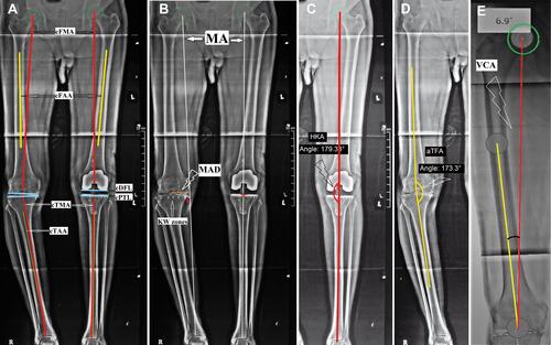
Figure 1 Assessment in the coronal plane (AP radiograph).
Using the above axes and lines, the following variables are measured:Citation2,Citation5,Citation19,Citation20
Mechanical axis deviation (MAD) (): is measured as a perpendicular line drawn from Maquet’s line (which is the mechanical axis (MA) of the lower limb extending from femoral head center to center of talar dome)Citation23,Citation24 to the center of the knee; it normally measures 9.7±6.8 mm.Citation19,Citation20 The relationship between MA and the center of the knee, identified as MAD, is linear; for every 1° of valgus or varus, the MA moves for about 5 mm away from the knee’s center. The tibial plateau has been divided into seven zones (from medial to lateral: zones 0, 1, 2, C, 3, 4, 5) and the passage of the MA through the knee can be described according to which of these Kennedy and White zones (KW zones) the MA lies within.Citation25–Citation27
The hip-knee-ankle angle (HKA) (): is the medial angle between the cFMA and the cTMA, indicating the limb’s mechanical alignment. A neutral mechanical alignment is varus 1.3 ± 1.3°,Citation19 and an angle of 0 ± 3° (180 ± 3°) is the classic safe target for alignment after TKA.Citation28
Anatomical tibiofemoral angle (aTFA) (): the medial angle between the cFAA and the cTAA, indicating the limb’s anatomical alignment. Normally it measures valgus 7° ± 1.4.Citation19 A valgus angle between 2.4° and 7.2° after TKA is considered neutral anatomic alignment.Citation1
Valgus correction angle (VCA)Citation29 (): the angle between the cFMA and cFAA determines the distal femoral cut angle in TKA. It had been reported to range between 3 and 11 degrees.Citation29
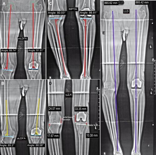
Mechanical lateral distal femoral angle (mLDFA) (): is the lateral angle formed between the cFMA and cDFL; normally, it measures 87.8° ± 1.6.Citation19,Citation20 The femoral component position in the coronal plane should be placed at 90° ± 3 to the cFMA or according to the preoperatively measured VCA.Citation29,Citation30
Anatomical lateral distal femoral angle (aLDFA) (): is the lateral angle between the FAA and cDFL. Normally it ranges from 79° to 83°.Citation19 An angle of 85° ± 2 is considered acceptable after TKA.Citation30
Medial proximal tibial angle (MPTA) (): (The β tibial angle in the KS scoring system) is the medial angle formed between the TMA and cPTL; normally, it measures 87.2° ± 1.5.Citation19,Citation20 It reflects the tibial component position in the coronal plane, an angle between 0 to varus 3 degrees (90° to 87°) being considered safe.Citation31
Joint line height (cJLH)Citation32,Citation33 (): The distance from the joint line (the line connecting the medial and lateral joint space or the line connecting the most distal points of the medial and lateral femoral condyles) to a fixed bony landmark, proximally as the medial femoral epicondyle or distally as the fibular head. It is usually 25 to 28 mm from the medial femoral epicondyle and 10 to 14 mm from the fibular head.Citation32,Citation33
Leg length difference (LLD)Citation34 (): is measured as the difference in the length of a line connecting the femoral head center to the center of the talus in the two limbs.
Component size: Ideally, the components should replicate the patient’s anatomy if possible. The femoral component should lie flush with the margins of the femoral condyles medially and laterally in the AP radiograph. The margins of correctly sized tibial components should likewise be flush with the medial and lateral cortices in AP views.Citation35,Citation36
Figure 2 Assessment in coronal plane continued.
Sagittal (s) Plane Evaluation (Lateral Radiographs)
Patient Positioning and Film Criteria
For a standard short film lateral knee view, the knee is flexed 30°; the patella should be perpendicular to the cassette, with the lower leg being parallel to the radiological table Obtaining as much as possible of the tibial and femoral shafts within the film is essential to detect any excessive bowing or extra-articular deformity (EAD).Citation19 An accurate lateral view of the knee should have no overlap between the medial and lateral femoral condyles. To obtain a lateral view of the whole femur (including the femoral heads), Chung et al positioned the patient’s thigh on a 17 x 17-inch digital detector with the x-ray beam angled at 15° cranially.Citation37
Sagittal (s) Plane MeasurementsCitation19,Citation20
Axis and lines determination ()
Femoral anatomical axis (sFAA): on the short film, it is a line obtained by joining a point at the middle of the femoral shaft (as proximal as possible in the film) with a second point placed at 10 cm proximal to the joint line in the middle of the femoral shaft. On a long film (showing the whole femur), the sFAA is obtained by drawing a line through the femoral shaft’s proximal, middle, and distal centers;Citation19 This produces a segmented line representing the sagittal femoral curve (normally between 4° and 9°).Citation37
Femoral mechanical axis (sFMA) (in a long film): it is the line drawn from the femoral head center to the center of the distal femur or the center of the femoral component.Citation19
Tibial anatomical axis (sTAA): is formed by connecting the most distal mid-point of the tibial shaft with a point located 10 cm distal to the knee joint line.Citation20
Tibial mechanical axis (sTMA): is the line between the center of the talus and the center of the tibial plateau or the tibial component (if the film shows the whole tibia).Citation19
Distal femoral line (sDFL): the distal femoral condyles are circular, so the DFL in the sagittal plane can be drawn as a straight line connecting two points where the condyles merge with the distal femoral metaphysis (for a native knee). For a femoral component after TKA, this line can be drawn either at the distal femur’s resection line or the line tangent to the intercondylar box (if a posterior stabilized implant was used).
Proximal tibial line (sPTL): is a line along the flat subchondral area of the tibial plateau for the native knee or a line tangent to the undersurface of the tibial component after TKA.
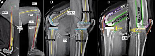
Figure 3 Assessment in the sagittal plane (Lateral radiograph).
Using the above axes and lines, the following variables are measured:Citation2,Citation5,Citation19,Citation20
Distal Femoral flexion angle (DFFA) (): is the posterior angle between the sFAA and the sDFL; normally, it is 83° ± 4.Citation20 It reflects the flexion or extension position of the femoral component (angle of 90 degrees is considered neutral, >90 degrees considered an extension, and <90 considered flexion. An angle from 90° to 87° is considered as accepted after TKA).Citation24
Tibial slope (TS) (): is the posterior angle between the sTAA and the sPTL, represented as the σ angle in the KS scoring system. The normal tibial slope is 81° ± 3.Citation20 Some authors advocate keeping the TS between 0° and 7° during TKA; however, this value may differ according to various implant designs.Citation38,Citation39
The posterior condylar offset (PCO) (): measured as the thickness of the posterior femoral condyles (either of the native femur or the femoral component after TKA) projected posteriorly from a tangent line over the posterior femoral cortex. It should be restored during TKA as a PCO decreases after surgery will affect knee flexion; for every 2 mm decrease in PCO, flexion is reduced by about 12.2°.Citation40
The anterior condylar offset (ACO) (): measured as the maximum thickness of the anterior condyles of the native knee or the anterior flange of the femoral component after TKA projected anteriorly from a tangent line to the anterior femoral cortex (serves as an indication of patellofemoral overstuffing).Citation41 Miller et al reported that following an increase of the ACO between 2 and 4 mm, the flexion decreases by 1.8° and 4.4°, respectively.Citation42
Patellar height (can be measured using different techniques):Citation43
Insall-Salvati Index (ISI) (): it is the ratio between the patellar tendon length (measured from its origin at the patellar lower pole to its insertion in the tibial tuberosity, line B) and the length of the patella (measured as the longest diagonal line across the patella, line A). Normally, the ratio is about 1.02, with a variation of less than 20%. A ratio greater than 1.2 indicates a patella Alta, and if lower than 0.8 indicates a patella Baja.Citation44
Caton-Deschamps Index (CDI) (): it is the ratio between the length of the patellar articular surface (line C) and the length of the distance from the inferior pole of the patella to the superior margin of the tibial plateau (line D). The normal value is 1.0 (0.8–1.2), a ratio higher than 1.3 indicates a patella Alta, and lower than 0.7 suggests a patella Baja.Citation45 The use of the ISI is theoretically favored over the CDI because it is not adversely affected by the position of the joint line, which can be altered by surgery.Citation46
The joint line height (sJLH) (): is measured as the perpendicular distance from the weight-bearing parallel surface of the tibial plateau or the most distal points of the femoral component to the tip of the fibular head.Citation47
Femoral notching: Anterior femoral cortical notching can be visualized in a lateral view. It acts as a stress riser at the anterior femoral cortex and may increase supracondylar fracture risk.Citation48
Component size: An oversized femoral component can overstuff the patellofemoral joint or create a tight flexion gap to reduce the range of flexion. An undersized femoral component can cause instability in flexion due to a large flexion gap.Citation49 The tibial component should not overhang posteriorly to avoid post TKA flexion deformity or any impingement.Citation50
Axial (a) Plane Evaluation (Axial and Special View Radiographs)
Patient Positioning and Film Criteria
There are variations in positions described for axial plane assessment of the patellofemoral joint,Citation51 the most commonly used one being Merchant’s view where the patient is supine on the radiological table with the knees flexed at 90°, and the cassette is placed proximally at the tibial shins. Both knees are exposed simultaneously with the beam directed from proximal to distal at 30° from the horizontal.Citation52
The kneeling view for distal femoral (and femoral component) rotational assessment and the technique for obtaining this view was described by Takai et al.Citation11 The patient is seated on the edge of a radio-transparent table with the knee flexed to 90°, and the beam is passed from posterior either perpendicular to the tibial shaft or inclined 15° to the horizontal plane from inferiorly. The resultant radiograph is a posterior-anterior view of a flexed knee showing the detailed anatomy of the distal femur.
Axial Plane MeasurementsCitation11,Citation53
Axis and lines determination ()
Anterior femoral condylar line (AFCL): line passing tangent to the anterior femoral condyles of a native distal femur or the femoral component after TKA.
Patellar axis (PA): line passing from the medial to the lateral poles of the patella (equator).
Posterior condylar line (PCL) (in kneeling view): line passing tangentially to the posterior femoral condyles of a native femur or of the femoral component after TKA.
Transepicondylar axis (TEA) (in kneeling view): it could be either the anatomical axis (aTEA) represented by a line connecting the medial and lateral femoral epicondyles, or the surgical axis (sTEA) represented by a line connecting the medial sulcus with the lateral epicondyle.
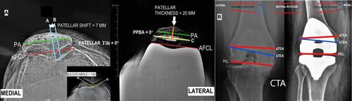
Figure 4 Assessment in the axial plane (special views).
Patellofemoral Joint MeasurementsCitation2,Citation5,Citation53,Citation54
Sulcus angle (measured in the native knee) (): is the angle formed between the lateral and medial anterior femoral condyles at the femoral sulcus trough; its normal value is 135° ± 10, with an increased angle indicating trochlear dysplasia and an increased incidence of patellar instability.Citation55
Patellar tilt: is the angle between the AFCL and the PA line for a native or unresurfaced patella (represented by the bone prosthesis interface line in a resurfaced patella after TKA); the patella should lie at the center of the trochlear groove in Merchant’s view; if the patella is tilted laterally, the angle is positive (this is considered normal up to 5º) if the angle is >5º it indicates patellar instability,Citation4 while if it is 0º or negative the patellar tilt is abnormal. A small or negative angle indicates a subluxation or a dislocation. It corresponds to (γ) angle in the KS scoring system.Citation17
The patellar thickness: is the vertical distance from the patella’s anterior cortex to the deepest point of the patellar articular surface. Increased patellar thickness can alter the tracking and reduce the range of flexion;Citation56 Benges and Scott showed in a study on cadavers that the flexion decreased by 3° for every 2 mm incrementation of the patellar thickness.Citation57
Patellar shift: is the mediolateral position of the patella measured as the horizontal distance between two vertical lines; the first line is passing through the medial ridge of the patella (line A) and another line passing through the deepest part of the trochlear groove (line B). Patella should be positioned on the medial two-thirds of the trochlear groove.Citation58 It corresponds to (δ) in the KS scoring system.Citation2 Chia et al reported that a preoperative lateral patellar shift of more than 3 mm was an independent risk factor for patellar maltracking after TKA.Citation59
Patellar prosthesis-bone angle (PPBA): is the angle formed between the PA of the patella’s remnant and the tangent to the bone-implant interface (line C). The patellar prosthesis-bone angle can determine an asymmetrical bone cut of the patella during resurfacing.
Condylar Twist Angle (CTA)Citation11,Citation60
In the kneeling view, it is measured as the angle between the PCL and the aTEA (if aTEA cannot be identified, the sTEA can be used instead) (). It is used to determine the amount of preoperative distal femoral torsion of a native femur or the femoral component rotation after TKA. The rotational direction will be determined by the direction of rotation of the PCL in relation to the TEA. The preoperative CTA can differ greatly according to the arthritic process or ethnic differences; however, the postoperative CTA should be neutral (PCL parallel to aTEA) or between 3° and 4° of external rotation if measured in reference to the sTEA.Citation11,Citation61
All the previously mentioned parameters are listed in () (the measurements which could not be performed either pre- or post-TKA, their spaces are blocked) which may serve as a guide for the surgeon for preoperative as well as post-TKA radiographic assessment. Although plain radiographs play the main role in the diagnosis and assessment of patients undergoing TKA, however, it is subject to human errors. Advanced imaging studies like CT and MRI may be needed in specific situations.
Table 1 Radiographic Parameters for Knee Assessment Pre, Post, and for Follow-Up of TKA
Conclusion
In this review, we followed a systematic protocol for knee radiographic assessment pre- and post-TKA; we tried to collect all the possible commonly reported variables (angles, ratios, and indices) needed for preoperative planning and postoperative evaluation. We believe that this review could guide surgeons for the proper technique of radiographic evaluation; however, each surgeon could define the useful variables for his daily practice. Furthermore, these angles and measurements could differ according to the design of the prosthesis used and the manufacturer’s recommendations for implant positioning, as well as the alignment and balancing philosophy upon which the TKA is performed. All the reported measurements should be evaluated in conjunction with functional outcomes as well as patients satisfaction.
Abbreviations
TKA, total knee arthroplasty; CT, computed tomography; MRI, magnetic resonance imaging; HKA, Hip Knee Ankle; c, coronal; FAA, femoral anatomical axis; FMA, femoral mechanical axis; TAA, tibial anatomical axis; TMA, tibial mechanical axis; DFL, distal femoral line; PTL, proximal tibial line; MAD, mechanical axis deviation; MA, mechanical axis; aTFA, anatomical tibiofemoral angle; VCA, valgus correction angle; mLDFA, mechanical lateral distal femoral angle; aLDFA, anatomical lateral distal femoral angle; MPTA, medial proximal tibial angle; JLH, joint line height; LLD, leg length difference; s, Sagittal; DFFA, distal femoral flexion angle; TS, tibial slope; PCO, posterior condylar offset; ACO, anterior condylar offset; ISI, Insall-Salvati Index; CDI, Caton-Deschamps Index; a, axial; AFCL, anterior femoral condylar line; PA, patellar axis; PCL, posterior condylar line; TEA, transepicondylar axis; PPBA, patellar prosthesis-bone angle; CTA, condylar twist angle.
Consent for Publication
Authors declare that images are entirely unidentifiable, and there are no details on individuals reported in the published version.
Author Contributions
All authors made substantial contributions to conception and design, acquisition of data, or analysis and interpretation of data; took part in drafting the article or revising it critically for important intellectual content; agreed to submit to the current journal; gave final approval of the version to be published; and agreed to be accountable for all aspects of the work.
Disclosure
The authors reported no conflicts of interest for this work.
Additional information
Funding
References
- Tanzer M, Makhdom AM. Preoperative planning in primary total knee arthroplasty. J Am Acad Orthop Surg. 2016;24(4):220–230. doi:10.5435/JAAOS-D-14-00332
- Meneghini RM, Mont MA, Backstein DB, Bourne RB, Dennis DA, Scuderi GR. Development of a modern knee society radiographic evaluation system and methodology for total knee arthroplasty. J Arthroplasty. 2015;30(12):2311–2314. doi:10.1016/j.arth.2015.05.049
- Sardana V, Burzynski JM, Khan M, Stone N, Weening BS, Zalzal PK. Long-term functional outcomes and knee alignment of computer-assisted navigated total knee arthroplasty. Musculoskelet Surg. 2017;101(1):37–43. doi:10.1007/s12306-016-0442-z
- Kumar N, Yadav C, Raj R, Anand S. How to interpret postoperative X‐rays after total knee arthroplasty. Orthop Surg. 2014;6(3):179–186. doi:10.1111/os.12123
- Ewald FC. The knee society total knee arthroplasty roentgenographic evaluation and scoring system. Clin Orthop Relat Res. 1989;(248):9–12.
- Riviere C, Iranpour F, Auvinet E, et al. Alignment options for total knee arthroplasty: a systematic review. OTSR. 2017;103(7):1047–1056. doi:10.1016/j.otsr.2017.07.010
- Hirschmann MT, Moser LB, Amsler F, Behrend H, Leclercq V, Hess S. Phenotyping the knee in young non-osteoarthritic knees shows a wide distribution of femoral and tibial coronal alignment. Knee Surg Sports Traumatol Arthrosc. 2019;27(5):1385–1393. doi:10.1007/s00167-019-05508-0
- Khalifa A, Bakr H, Said E, Mahran M. Technical note on using intraoperative smartphone applications to adjust cup inclination angle during Total Hip Arthroplasty (THA). Archiv Bone Joint Surg. 2020;8(6):734–738. doi:10.22038/abjs.2020.44466.2217
- Khalifa AA, Fayez M, Elkady H, Abdelaal AM, Elassal MA. The outcome of posterior-stabilized, rotating platform total knee arthroplasty at a minimum ten-year follow-up, a middle east institution experience. J Knee Surg. 2020. doi:10.1055/s-0040-1716850
- Langella F, Villafane JH, Damilano M, et al. Predictive accuracy of surgimap surgical planning for sagittal imbalance: a cohort study. Spine. 2017;42(22):E1297–E1304. doi:10.1097/BRS.0000000000002230
- Takai S, Yoshino N, Isshiki T, Hirasawa Y. Kneeling view: a new roentgenographic technique to assess rotational deformity and alignment of the distal femur. J Arthroplasty. 2003;18(4):478–483. doi:10.1016/S0883-5403(03)00065-2
- Stickley CD, Wages JJ, Hetzler RK, Andrews SN, Nakasone CK. Standard radiographs are not sufficient for assessing knee mechanical axis in patients with advanced osteoarthritis. J Arthroplasty. 2017;32(3):1013–1017. doi:10.1016/j.arth.2016.09.024
- Dargel J, Pennig L, Schnurr C, Boese CK, Eysel P, Oppermann J. Ist die postoperative Ganzbeinaufnahme nach Knie-TEP-Implantation notwendig? [Should we use hip-ankle radiographs to assess the coronal alignment after total knee arthroplasty?]. Der Orthopade. 2016;45(7):591–596. German. doi:10.1007/s00132-016-3264-7
- Radtke K, Becher C, Noll Y, Ostermeier S. Effect of limb rotation on radiographic alignment in total knee arthroplasties. Arch Orthop Trauma Surg. 2010;130(4):451–457. doi:10.1007/s00402-009-0999-1
- Jiang CC, Insall JN. Effect of rotation on the axial alignment of the femur. Pitfalls in the use of femoral intramedullary guides in total knee arthroplasty. Clin Orthop Relat Res. 1989;(248):50–56.
- Deep K, Eachempati KK, Apsingi S. The dynamic nature of alignment and variations in normal knees. Bone Joint J. 2015;97–B(4):498–502. doi:10.1302/0301-620X.97B4.33740
- Hsu RW, Himeno S, Coventry MB, Chao EY. Normal axial alignment of the lower extremity and load-bearing distribution at the knee. Clin Orthop Relat Res. 1990;(255):215–227.
- Tang WM, Zhu YH, Chiu KY. Axial alignment of the lower extremity in Chinese adults. J Bone Joint Surg Am. 2000;82(11):1603–1608. doi:10.2106/00004623-200011000-00014
- Paley D. Radiographic assessment of lower limb deformities. In: Principles of Deformity Correction. Berlin, Heidelberg: Springer Berlin Heidelberg; 2002:31–60.
- Paley D, Herzenberg JE, Tetsworth K, McKie J, Bhave A. Deformity planning for frontal and sagittal plane corrective osteotomies. Orthop Clin North Am. 1994;25(3):425–465. doi:10.1016/S0030-5898(20)31927-1
- Paley D, Tetsworth K. Mechanical axis deviation of the lower limbs. Preoperative planning of uniapical angular deformities of the tibia or femur. Clin Orthop Relat Res. 1992;(280):48–64.
- Luo CF. Reference axes for reconstruction of the knee. Knee. 2004;11(4):251–257. doi:10.1016/j.knee.2004.03.003
- Maquet P. Biomécanique de la gonarthrose [Biomechanics of gonarthrosis]. Acta Orthop Belg. 1972;38(Suppl 1):33–54. French.
- Al-Hadithy N, Papanna MC, Farooq S, Kalairajah Y. How to read a postoperative knee replacement radiograph. Skeletal Radiol. 2012;41(5):493–501. doi:10.1007/s00256-011-1297-x
- Mullaji AB, Shah S, Shetty GM. Mobile-bearing medial unicompartmental knee arthroplasty restores limb alignment comparable to that of the unaffected contralateral limb. Acta orthopaedica. 2017;88(1):70–74. doi:10.1080/17453674.2016.1253327
- Kennedy WR, White RP. Unicompartmental arthroplasty of the knee. Postoperative alignment and its influence on overall results. Clin Orthop Relat Res. 1987;(221):278–285.
- Subramanian SS, MoongilpattiSengodan M. Role of full length weight bearing radiograph in assessing the alignment in total knee arthroplasty. IOSR J Dent Med Sci. 2016;15(07):55–63. doi:10.9790/0853-150785563
- Allen MM, Pagnano MW. Neutral mechanical alignment: is it necessary? Bone Joint J. 2016;98-B(1 Suppl A):81–83. doi:10.1302/0301-620X.98B1.36403
- Mullaji AB, Shetty GM, Kanna R, Vadapalli RC. The influence of preoperative deformity on valgus correction angle: an analysis of 503 total knee arthroplasties. J Arthroplasty. 2013;28(1):20–27. doi:10.1016/j.arth.2012.04.014
- Park A, Stambough JB, Nunley RM, Barrack RL, Nam D. The inadequacy of short knee radiographs in evaluating coronal alignment after total knee arthroplasty. J Arthroplasty. 2016;31(4):878–882. doi:10.1016/j.arth.2015.08.015
- Berend ME, Ritter MA, Meding JB, et al. Tibial component failure mechanisms in total knee arthroplasty. Clin Orthop Relat Res. 2004;428(428):26–34. doi:10.1097/01.blo.0000148578.22729.0e
- Luyckx T. The Tibio-Femoral Joint Line: What is the Biomechanical and Clinical Effect of Surgical Modifications? Faculty of Medicine and Health Sciences; KU Leuven, Faculty of Medicine, Ghent Ghent University; 2015.
- Servien E, Viskontas D, Giuffre BM, Coolican MR, Parker DA. Reliability of bony landmarks for restoration of the joint line in revision knee arthroplasty. Knee Surg Sports Traumatol Arthrosc. 2008;16(3):263–269. doi:10.1007/s00167-007-0449-y
- Harvey WF, Yang M, Cooke TD, et al. Association of leg-length inequality with knee osteoarthritis: a cohort study. Ann Intern Med. 2010;152(5):287–295. doi:10.7326/0003-4819-152-5-201003020-00006
- Simsek ME, Akkaya M, Gursoy S, et al. Posterolateral overhang affects patient quality of life after total knee arthroplasty. Arch Orthop Trauma Surg. 2018;138(3):409–418. doi:10.1007/s00402-017-2850-4
- Mahoney OM, Kinsey T. Overhang of the femoral component in total knee arthroplasty: risk factors and clinical consequences. J Bone Joint Surg Am. 2010;92(5):1115–1121. doi:10.2106/JBJS.H.00434
- Chung BJ, Kang YG, Chang CB, Kim SJ, Kim TK. Differences between sagittal femoral mechanical and distal reference axes should be considered in navigated TKA. Clin Orthop Relat Res. 2009;467(9):2403–2413. doi:10.1007/s11999-009-0762-5
- Dorr LD, Boiardo RA. Technical considerations in total knee arthroplasty. Clin Orthop Relat Res. 1986;(205):5–11.
- Rassir R, van de Bunt F, Sierevelt IN, Nolte PA. The value of postoperative prosthesis alignment and patellar height measurements on standard X-rays after total knee arthroplasty: does it relate to knee function after 5years? Knee. 2019;26(1):213–221. doi:10.1016/j.knee.2018.09.014
- Bellemans J, Banks S, Victor J, Vandenneucker H, Moemans A. Fluoroscopic analysis of the kinematics of deep flexion in total knee arthroplasty. Influence of posterior condylar offset. J Bone Joint Surg Br. 2002;84(1):50–53. doi:10.1302/0301-620X.84B1.0840050
- Clarke HD, Hentz JG. Restoration of femoral anatomy in TKA with unisex and gender-specific components. Clin Orthop Relat Res. 2008;466(11):2711–2716. doi:10.1007/s11999-008-0454-6
- Miller RK, Goodfellow JW, Murray DW, O’Connor JJ. In vitro measurement of patellofemoral force after three types of knee replacement. J Bone Joint Surg Br. 1998;80-B(5):900–906. doi:10.1302/0301-620X.80B5.0800900
- Eshnazarov KE, Seon JK, Song EK. Comparison of radiological assessments patellar resurfacing with retention for grade IV osteoarthritis in patellofemoral joint accomplished total knee arthroplasty. Vestn Rentgenol Radiol. 2016;97(1):28–32. doi:10.20862/0042-4676-2016-97-1-28-32
- Insall J, Salvati E. Patella position in the normal knee joint. Radiology. 1971;101(1):101–104. doi:10.1148/101.1.101
- Caton J, Deschamps G, Chambat P, Lerat JL, Dejour H. Patella infera. Apropos of 128 cases [Patella infera. About 128 cases]. Revue de chirurgie orthopedique et reparatrice de l’appareil moteur. 1982;68(5):317–325. French.
- Sarmah SS, Patel S, Hossain FS, Haddad FS. The radiological assessment of total and unicompartmental knee replacements. J Bone Joint Surg Br. 2012;94-B(10):1321–1329. doi:10.1302/0301-620X.94B10.29411
- Selvarajah E, Hooper G. Restoration of the joint line in total knee arthroplasty. J Arthroplasty. 2009;24(7):1099–1102. doi:10.1016/j.arth.2008.06.030
- Gujarathi N, Putti AB, Abboud RJ, MacLean JG, Espley AJ, Kellett CF. Risk of periprosthetic fracture after anterior femoral notching. Acta Orthopaedica. 2009;80(5):553–556. doi:10.3109/17453670903350099
- Lo CS, Wang SJ, Wu SS. Knee stiffness on extension caused by an oversized femoral component after total knee arthroplasty: a report of two cases and a review of the literature. J Arthroplasty. 2003;18(6):804–808. doi:10.1016/S0883-5403(03)00331-0
- Miller TT. Imaging of knee arthroplasty. Eur J Radiol. 2005;54(2):164–177. doi:10.1016/j.ejrad.2005.01.020
- Mulligan ME, Jones ED. Femoral sulcus angle measurements. Am J Orthoped. 1997;26(8):541–543.
- Merchant AC, Mercer RL, Jacobsen RH, Cool CR. Roentgenographic analysis of patellofemoral congruence. J Bone Joint Surg Am. 1974;56(7):1391–1396. doi:10.2106/00004623-197456070-00007
- Dutton RA, Khadavi MJ, Fredericson M. Patellofemoral Pain. Phys Med Rehabil Clin N Am. 2016;27(1):31–52. doi:10.1016/j.pmr.2015.08.002
- Gomes LS, Bechtold JE, Gustilo RB. Patellar prosthesis positioning in total knee arthroplasty. A roentgenographic study. Clin Orthop Relat Res. 1988;(236):72–81.
- Davies AP, Costa ML, Shepstone L, Glasgow MM, Donell S. The sulcus angle and malalignment of the extensor mechanism of the knee. J Bone Joint Surg Br. 2000;82-B(8):1162–1166. doi:10.1302/0301-620X.82B8.0821162
- Hsu HC, Luo ZP, Rand JA, An KN. Influence of patellar thickness on patellar tracking and patellofemoral contact characteristics after total knee arthroplasty. J Arthroplasty. 1996;11(1):69–80. doi:10.1016/S0883-5403(96)80163-X
- Bengs BC, Scott RD. The effect of patellar thickness on intraoperative knee flexion and patellar tracking in total knee arthroplasty. J Arthroplasty. 2006;21(5):650–655. doi:10.1016/j.arth.2005.07.020
- Lewonowski K, Dorr LD, McPherson EJ, Huber G, Wan Z. Medialization of the patella in total knee arthroplasty. J Arthroplasty. 1997;12(2):161–167. doi:10.1016/S0883-5403(97)90062-0
- Chia SL, Merican AM, Devadasan B, Strachan RK, Amis AA. Radiographic features predictive of patellar maltracking during total knee arthroplasty. Knee Surg Sports Traumatol Arthrosc. 2009;17(10):1217–1224. doi:10.1007/s00167-009-0832-y
- Savin L, Botez P, Mihailescu D, Predescu V, Grierosu C. Pre-operative radiological measurement of femoral rotation for prosthetic positioning in total knee arthroplasty. Int Orthop. 2016;40(9):1855–1860. doi:10.1007/s00264-015-3110-2
- Viel T, Casin C, Ducellier F, Steiger V, Bigorre N, Bizot P. Is radiographic measurement of distal femoral torsion reliable? OTSR. 2013;99(5):517–522. doi:10.1016/j.otsr.2013.02.009