 ?Mathematical formulae have been encoded as MathML and are displayed in this HTML version using MathJax in order to improve their display. Uncheck the box to turn MathJax off. This feature requires Javascript. Click on a formula to zoom.
Abstract
We demonstrate how a mechanical point-contact technique can provide information on the wavenumber of spin waves excited by high-density electrical current in magnetic multilayers. By varying the size of point-contacts, we have been able to control the size of the excitation volume and therefore the wavelength of current-induced spin waves. This leads to a technique with in situ sensitivity to wavenumbers of current-induced excitations. Our detailed size-dependent measurements support the prediction that the excited wavelength is determined by the contact size.
Introduction
It is well known that the magnetic state of a ferromagnet can be affected by high-density electric current via the spin-transfer-torque (STT) effect.Citation1,Citation2 For instance, current was shown to induce spin waves, precession, and reversal of magnetization in magnetic multilayered structures.Citation3–Citation6 Today, a variety of resistance measurements generate a vast amount of data on such STT excitations, including experiments at high frequencies (1–60 GHz), which provide valuable information on their frequency characteristics.Citation7–Citation10 Probing spatial characteristics (eg, wavenumber) of the excitations, however, represents an experimental challenge. For instance, SlonczewskiCitation11 has argued that the current-induced wavelength is determined by the size of the excitation region where current density is high and, thus, we would require a technique capable to probe magnetization on a nanometer scale. Recently ultrafast X-ray microscopy was used to directly visualize the current-induced reversals in magnetic nanopillars with cross-sectional areas>104 nm2.Citation12 Excitation regions with sizes down to ~103 nm2 were probed in experiments with lithographic point-contacts.Citation13 Here we present an experimental technique which exploits mechanical point-contacts and allows in situ tuning of the excitation region down to 102 nm2 in size.
Mechanical point-contacts were instrumental both for our original observation of current-induced excitationsCitation3 and in providing the first data on frequencies of the current-induced spin waves.Citation7 In this paper, we describe how such contacts can be used to infer indirect information about the wavenumber (or wavelength) of spin waves induced by the current. By varying the size of point-contacts, we have been able to control the size of the excitation volume and therefore the wavelength of current-induced excitations. This leads to a technique with in situ sensitivity to the wavelength of excitations. Our detailed size-dependent measurements of the current-induced spin waves and analysis of the data based on three different theoretical models support the predictionCitation11 that the excited wavelength is determined by the size of the excitation volume.
Materials and methods
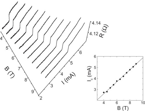
Our [cobalt (1.5 nm)/copper (2 nm)]20 multilayered films were fabricated by radio frequency (RF) magnetron sputtering in an ultra-high-vacuum compatible system (base pressure 2 × 10⁻⁹ Torr). The films were sputtered in 5 mTorr of argon onto silicon substrates. The usual current-in-plane magnetoresistance was measured (not shown) to be about 5%. Point contacts to the multilayer film were made with a standard systemCitation3,Citation14,Citation15 where a sharpened copper wire (tip) was carefully brought into contact with the film using a differential screw mechanism. The resulting contact area can be estimated from the measured contact resistance, assuming a combination of ballistic and diffusive electron transport through the contact,Citation14,Citation15 as described later. For a typical contact of 10 Ω, this gives an extremely small area of about 102 nm2, enabling current densities up to 1013 A/m2 to be injected into the multilayer. We, and others, have observed such high densities to produce a step-increase in contact resistance corresponding to the onset of spin-wave excitations. shows an example of such behavior for a fixed contact size. Solid traces show variations of the contact resistance R as a function of the bias current I recorded at different applied magnetic fields B. The measurements were taken at room temperature (295°K) and in out-of-the-plane magnetic fields larger than the saturation field of the multilayer (~1.5 T). The insert to shows that the critical bias current Ic(B), where the step-increase in R occurs, shifts linearly with B, similar to our original observations,Citation3 at liquid helium temperature (4.2°K).
Figure 1 Current-induced excitations at different magnetic fields for a fixed contact size.
In our present experiment, we are able to vary the pointcontact size in a single experimental run. According to predictions,Citation1,Citation2 the contact size defines the wavelength of the current-induced excitations and also the slope and intercept of Ic(B). Thus, measuring the dependence of Ic(B) on the contact size would provide indirect information on the current-driven wavelength. Next, we describe how the size of a point-contact is controlled in our experiments.
As mentioned above, a mechanical point-contact is created when a sharp metal tip is brought into contact with a multilayer sample. After establishing the initial contact (usually small) between the tip and the sample surface, the contact size can be varied (increased) by further pressing the tip to the multilayer film. The extent of the damage to the film is controlled by relative mechanical strength of the tip and the multilayer sample. By choosing a soft tip (copper) it is possible to minimize the damage to the sample and constrain most of deformations within the tip. The tip material is further softened by Joule heating when a high current is applied to the contact. The increase in contact size is inferred from the decrease in contact resistance, which is monitored throughout the heating procedure. This method provides a means to increase the contact size in a highly controllable manner. However, the process is irreversible, as we can only increase, not decrease, the contact size.
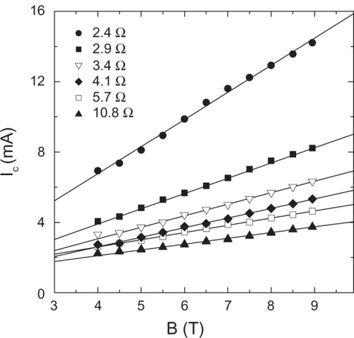
Using the above method to vary the size of a point-contact, we have measured Ic(B) for contacts with areas ranging from 102–104 nm2. The experimental procedure was as follows: (i) I – V (current – voltage) characteristics of a contact with a given resistance R = V/I are measured at different applied fields (see ). (ii) This gives Ic(B) for the given R (see inset to ). (iii) The contact resistance is reduced to a new value. The measurement cycle (i–iii) is repeated to cover a wide range of resistance values. The total of seven experimental runs have shown similar results, which we discuss next for a representative contact with a wide range of resistances. shows Ic(B) for resistance R ranging from 10.8 Ω down to 2.4 Ω. In what follows, we first describe how the contact size is defined from the measured contact resistance, then explain how the Ic(B) data can be used to recover the wavelength of the current-driven excitations, and finally make a direct comparison of our results with theory.
Figure 2 Dependence of critical current Ic(B) for a point-contact of variable size.
Discussion
The problem of contact resistance, or more generally, of electron transport through the contact has been studied for more than a century. MaxwellCitation16 found the resistance of a circular point-contact of radius a between two large conductors when the electron mean-free-path l is much smaller than a (diffusive regime): RM = ρ/2a, where ρ is the resistivity of conductors. SharvinCitation17 calculated that the point-contact resistance in the ballistic regime (l >> a) – RS = 4ρl/3πa2, where ρl ≈ 1 fΩ m2, is a similar constant for most metals.Citation18 Nikolic and AllenCitation19 obtained an exact result for an arbitrary ratio l/a, that interpolates between Maxwell resistance in the diffusive and Sharvin resistance in the ballistic regime. An approximate expression for contact resistance R can be written as:Citation20
where Γ(K) is a slowly varying function of the Knudsen number K = l/a, with Γ(K = 0) = 1 and Γ(K = ∞) = 0.694. Since our measurements were done at room temperature and most likely l && a, we use Γ = 1 in our estimations. For the contact in , EquationEquation 1(1) gives a increasing from 8 nm (for R = 10.8 Ω) to 24 nm (for R = 2.4 Ω).
By comparing the measured Ic(B) dependence with the one predicted by theory it is possible to infer the wavelength λ of the current-induced excitations. First, we obtain a slope α and intercept β of the linear fit to Ic(B) data (see ). For instance, for R = 2.4 Ω, the linear fit gives Ic= αB +β = 15.4 × 10⁻⁴(A/T) × B + 6.0 × 10⁻⁴(A). The measured values of α and β can now be compared with theory, where the slope α′ and/or intercept β′ of the Ic = α′B + β′ dependence are expected to depend on the excitation’s wavelength λ Next, we show how three different theoretical models for the current-induced excitations can be used to elucidate λ from our data.
The first model we explore for wavelength calculations is the original spin-torque model by Slonczewski.Citation1,Citation11 Here, the critical current Ic to induce spin waves in an unbounded ferromagnetic film is given as a function of applied field B and contact radius a (Eq. 13 in reference 21):
where Beff = B – μ0Ms, t is thickness of the excited layer, αG damping parameter, ɛ spin-polarization parameter, A exchange stiffness, and Ms saturation magnetization. The model assumes that λ is equivalent to a. Using t = 1.5 × 10⁻⁹ m, αG = 0.05, ɛ = 0.5, A = 1 × 10–11 J/m, and Ms = 1.45 × 10⁶ A/m (all for cobalt), we have α′ = 2.09 × 10⁻⁶λ2 nm2 and β′ = 1.07 × 10⁻³ – 3.8 × 10⁻⁶λ2 nm2. Here both slope α′ and intercept β′ depend on λ and may be used to find λ from experimental data.
The second model we use for wavelength calculations explores Berger’s condition for the current-induced emission of spin waves in a ferromagnetic/non-magnetic (F/N) metal multilayer.Citation2 Here, the energy for the spin waves comes from conduction electrons whose spin-up and spin-down Fermi surfaces are shifted (in k-space) in the direction of the current flow by a different amount due to a difference between the spin-up (σ↑) and spin-down (σ↓) conductivities in F These shifts produce shifts of the local spin-up (Δμ↑) and spin-down (Δμ↓) Fermi levels at a given point of the Fermi surface. The resulting difference between Δμ↑ and Δμ↓ in the direction of the current flow is given by Eq. 23 in reference 2:
where α1 = σ↑/σ↓ is the asymmetry parameter, j = I/πa2 the current density, kN the Fermi wave vector in N, and nN the electron density in N.
Note that the emission of spin waves starts only when Δμ exceeds the spin-wave energy ħω. The condition Δμ+ħω= 0 defines the critical current lc for the excitations. Assuming a simple dispersion relation for spin waves in a thin F-filmCitation21
where D is stiffness (510 meVÅ2 for cobalt), g is Lande factor (2.170 for cobalt), and μB is Bohr magneton, and using α1 = 3, kN = 1.36 × 10¹⁰ m–1, nN = 8.5 × 1028 m–3, D = 510 meVÅ2, and g = 2.17, we find
Finally, our third calculation uses Δμ deduced from the solution of the diffusion equation for Δμ↑ and Δμ↓Citation22 as originally proposed for current-induced excitations in:Citation3
where j is the current density, σF and σN are F and N conductivities, ΛF and ΛN are spin diffusion lengths in F and N, and αF is the spin asymmetry coefficient in F Assuming room temperature parameters for F = cobalt and N = copper: σF−1 = 238 nΩm, σN−1 = 29 nΩm, ΛF≈15 nm, ΛN ≈350 nm, and αF = 0.75, we get Δμ = j × 3.24 × 10⁻¹⁵ (eV) and find:
which, along with Equationequations 2(2) and Equation5
(5) , may be used to find λ from our experimental data in , as we show next.
shows the results of our wavelength calculations. The solid line shows how the contact radius a depends on the contact resistance R according to Sharvin-Maxwell relation (EquationEq. 1(1) ) and will serve us as a reference. The filled symbols show the wavelength λ of current-driven spin waves calculated within Slonczewski’s spin-torque model (EquationEq. 2
(2) ) using our data from . The filled squares were obtained from the data for the slope α′ and mostly fall higher than the contact size a(R) dependence. The filled triangles are from the data for the intercept β′and mostly fall below a(R). The possible reason for the latter is the following: when calculating the effective field Beff = B – μoMS, we assumed that the F-film’s magnetization Ms is fully out-of-plane. However, in reality, the magnetization is precessing and tilted away from this perpendicular-to-plane orientation that should result in a larger effective field and thus, larger λ. For sufficiently large angles of precession, β′ in EquationEq. 2
(2) should be nearly independent of the contact size.
Figure 3 Wavelength λ of the current-driven spin waves versus contact (size) resistance R.
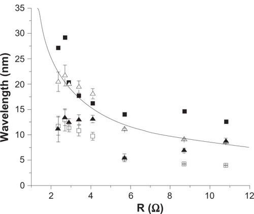
The open symbols in are the spin-wave wavelengths λ calculated from the Δμ=ħω condition. The open triangles show λ calculated within Berger’s model (EquationEq. 5(5) ). These symbols fall the closest to the reference a(R) curve. The open squares show λ obtained from EquationEq. 7
(7) . They all fall below the corresponding contact radius a. Since here we assumed a 100% efficiency of converting Δμ into the spin-wave energy, it is expected that λ(R) will be somewhat larger for a lower efficiency realized in our room temperature experiment. Overall, the analysis of our data using all three theoretical models suggests that the wavelength λ of the current-induced spin waves is close to the size of our point-contact.
Conclusion
In conclusion, we have presented a new experimental technique which provides a means to vary the size of a mechanical point-contact in situ in a single experimental run. We have used the technique to perform size-dependent measurements of the current-induced excitations (spin waves) in magnetic multilayers. Analysis of our experimental data based on three different theoretical models for the excitations suggests that the wavelength of spin waves induced by an electrical current in a point-contact is determined by the contact size. This information is of importance for possible realizations of on-chip communications based on spin-wave-bus technology.
Acknowledgments
The work was supported in part by NSF Grant No. DMR-06-45377.
Disclosures
The authors report no conflicts of interest in this work.
References
- SlonczewskiJCCurrent-driven excitation of magnetic multilayersJ Magn Magn Mater1996159117
- BergerLEmission of spin waves by a magnetic multilayer traversed by a currentPhys Rev B1996541393539358
- TsoiMJansenAGMBassJExcitation of a magnetic multilayer by an electric currentPhys Rev Lett1998801942814284
- MyersEBRalphDCKatineJALouieRNBuhrmanRACurrent-induced switching of domains in magnetic multilayer devicesScience1999285542986787010436150
- SunJZSpin angular momentum transfer in current-perpendicular nanomagnetic junctionsJ Magn Magn Mater19992021157164
- WegroweJEKellyDJaccardYGuittiennePAnsermetJPCurrent-induced magnetization reversal in magnetic nanowiresEurophys Lett1999455626632
- TsoiMJansenAGMBassJChiangWCTsoiVWyderOGeneration and detection of phase-coherent current-driven magnons in magnetic multilayersNature2000406464810894534
- KiselevSISankeyJCKrivorotovINMicrowave oscillations of a nanomagnet driven by a spin-polarized currentNature200342538038314508483
- RippardWHPufallMRKakaSRussekSESilvaTJDirect-Current Induced Dynamics in Co90Fe10/Ni80Fe20 Point ContactsPhys Rev Lett20049202720114753964
- KrivorotovINEmleyNCSankeyJCKiselevSIRalphDCBuhrmanRATime-domain measurements of nanomagnet dynamics driven by spin-transfer torquesScience2005307570722823115653496
- SlonczewskiJCExcitation of spin waves by an electric currentJ Magn Magn Mater1999195L261L268
- AcremannYStrachanJPChembroluVTime-resolved imaging of spin transfer switching: beyond the macrospin conceptPhys Rev Lett20069621720216803270
- MancoffFBRizzoNDEngelBNTehraniSArea dependence of high-frequency spin-transfer resonance in giant magnetoresistance contacts up to 300 nm diameterAppl Phys Lett20068811112507112513
- JansenAGMvan GelderAPWyderPPoint-contact spectroscopy in metalsJ Phys C198013336073
- TsoiMJansenAGMBassJSearch for point-contact giant magnetoresistance in Co–Cu multilayersJ Appl Phys19978155305532
- MaxwellJCA Treatise On Electricity and MagnetismOxford, UKClarendon Press1873
- SharvinYVA possible method for studying Fermi durfacesSov Phys JETP21655
- BassJLandolt Börnstein New Series, Vol III/15aHellwegeKHOlsenJLBerlin, GermanySpringer1982
- NikolicBAllenPBElectron transport through a circular constrictionPhys Rev B19996039633969
- WexlerGThe size effect and the non-local Boltzmann transport equation in orifice and disk geometryProc Phys Soc196689927
- AshcroftNWMerminNDSolid State PhysicsNew York, NYHolt, Rinehart, and Winston1976
- van SonPCvan KempenHWyderPBoundary resistance of the ferromagnetic-nonferromagnetic metal interfacePhys Rev Lett1987582271227310034698