Abstract
Conventional burr-hole buttons sometimes do not fit the burr hole well due to the curvature of the surrounding bone. An irregular surface at the border between the button and the surrounding skull may appear unaesthetic. The major problem is the difference between the curvature radius of the skull and the burr-hole button in contact with the skull. To solve this problem, the authors designed a button made of hydroxyapatite ceramic to snugly fit the burr hole. The specifications of this device and its clinical application are described here.
Introduction
Burr hole skull defects during neurosurgical operations are often reconstructed with titanium plates or burr-hole buttons made of hydroxyapatite ceramic to prevent skin indentation, with the latter being more biocompatible.Citation1–Citation3 A burr-hole button consists of two parts: the dome-shaped cap and the column. As the plane in contact with the skull (the inferior surface of the cap) is flat, this button often does not fit the burr hole well because of the curvature of the surrounding bone. An improper fit between the button and the surrounding skull may result in cosmetic problems. We devised a hydroxyapatite ceramic button to fit the curvature of the surrounding skull bone.
Description of the device
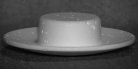
The burr-hole button is composed of multiporous hydroxyapatite ceramic material (porosity 30%) with a chemical formula of Ca10(PO)(OH)2. The molar ratio of calcareous substance to phosphorus is 1.67. In the dome-shaped cap, the plane in contact with the skull is concave in the superior direction (, ). The plane of the buttons was designed with three curvature radii: 70 mm, 50 mm and 30 mm (curvature radius is a term characterizing the measurement of the plane curvature). To reinforce the periphery of the burr hole cap, the thickness at the center of the cap was increased from 4.5 mm to 4.7 mm. The diameter of the cap was 17 × 17 mm and it had a tapered edge with a thickness of 0.5 mm at the periphery. The column, located in the center of the cap, was 8 mm in diameter and 3.3 mm in height.
Figure 1 Photograph showing the hydroxyapatite ceramic burr-hole button. In the dome-shaped cap, the plane in contact with the skull is concave in the superior direction.
We used three kinds of burr-hole buttons for intraoperative reconstruction of skull defects in ten patients, who underwent frontotemporal craniotomy. A burr-hole button was placed in the burr hole, which was positioned in the parietal bone along the linea temporalis behind the coronal suture. Burr-hole buttons with curvature radii of 70, 50, and 30 mm were used for two, four, and four patients, respectively. These buttons could be placed snugly in the burr hole.
Furthermore, we evaluated the usefulness of the buttons using a three-dimensional (3D) plaster-cast model of the skull. Four holes were made at the tuber frontale, tuber parietale, frontal bone surrounding the linea temporalis and frontal bone 3 cm lateral to the midline. The three novel burr-hole buttons and one conventional burr-hole button (HOYA Co, Tokyo, Japan) were placed in the holes, respectively (). The diameter of the holes corresponded to that of the burr holes, which were 8 mm in diameter. The skull model was made using computer-aided design in accordance with the patient’s 3D computed tomographic image data.
Figure 2 A) Photograph of the skull model showing the newly designed burr-hole buttons filling the burr holes at the tuber frontale, tuber parietale, frontal bone surrounding the linea temporalis and frontal bone 3 cm lateral to the midline. B) Photograph (tangential view) showing the burr-hole button with curvature radius of 30 mm placed in the burr hole defect at the tuber frontale. The border between the button and the surrounding skull model is smooth. C) Photograph (tangential view) showing the conventional burr-hole button placed in the burr hole defect at the tuber frontale. The border between the button and the surrounding skull model is irregular.
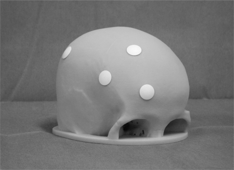
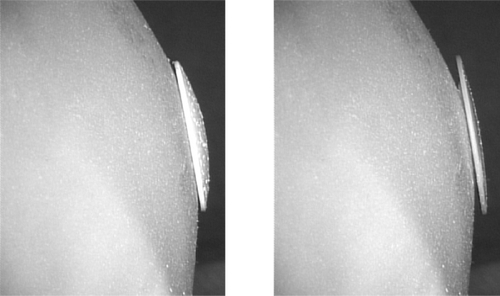
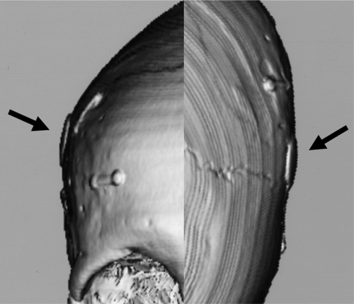
Figure 3 Three-dimensional computed tomography showing a burr hole placed snugly within the burr hole at the linea temporalis.
In the skull model, burr-hole buttons with a curvature radius of 70 and 50 mm fitted the holes at the frontal bone surrounding the linea temporalis and frontal bone 3 cm lateral to the midline. On the other hand, the burr-hole button with a curvature radius of 30 mm could be fitted anywhere (). The conventional burr-hole button fitted only the burr hole at the frontal bone 3 cm lateral to the midline ().
Discussion
Various types of burr-hole buttons have been developed to fill bone defects generated by burr holes and good cosmetic results have been obtained for typical burr holes over the convexity.Citation1,Citation4 Kobayashi and colleagues developed burr-hole buttons made of alumina ceramics to fill burr hole skull defects. The cap of their button was round and the plane in contact with the skin and skull was flat. Yamashita developed burr-hole buttons made of hydroxyapatite ceramics. Hydroxyapatite ceramic material is used for various clinical applications because it is soft, bioactive and biocompatible.Citation2,Citation3,Citation6,Citation7 The cap of their button was dome-shaped and the plane in contact with the skull was flat. However, their buttons could often not be placed snugly within burr holes at the more curved parts of the skull such as areas surrounding the tuber frontale, parietale and linea temporalis. The major cause of the problem was that the plane in contact with the skull was flat.
We designed our burr hole cap so that the plane would be in close contact with the skull, providing a smooth border when the burr-hole buttons were placed in the burr holes. In addition, in comparison with conventional burr-hole buttons, our buttons could be placed snugly within the burr hole in regions where the bone curvature in the skull model was pronounced.
With its excellent biocompatibility, bioactivity, and naturally fitting shape, this novel burr-hole button may help to improve the patient’s cosmetic appearance after craniotomy.
Acknowledgements
This instrument was developed with the assistance of HOYA Co, Tokyo, Japan. The authors report no conflicts of interest concerning the materials or methods used in this study or the findings specified in this paper.
References
- KobayashiSHaraHOkuderaHTakemaeTSugitaKUsefulness of ceramic implants in neurosurgeryNeurosurgery1987217517553696417
- KoyamaJHongoKIwashitaTKobayashiSA newly designed key-hole button. Technical noteJ Neurosurg20009350650810969954
- YamashimaTCranioplasty with hydroxylapatite ceramic plates that can easily be trimmed during surgery. A preliminary reportActa Neurochir198996149153
- YamashimaTReconstruction of surgical skull defects with hydroxylapatite ceramic button and granulesActa Neurochir198890157162
- AokiHScience and Medical Application of HydroxyapatiteTokyo, JapanJapanese Association of Apatite Science1991179192
- LiDJOhsakiKIiKYeQLong-term observation of subcutaneous tissue reaction to synthetic auditory ossicle (Apaceram) in ratsJ Laryngol Otol19971117027069327004
- OgisoMReassessment of long-term use of dense HA as dental implant: case reportJ Biomed Mater Res Appl Biomater199843318320