
Abstract
Aim: To develop a methodology for producing patient-specific scaffolds that mimic the annulus fibrosus (AF) of the human intervertebral disc by means of combining MRI and 3D bioprinting. Methods: In order to obtain the AF 3D model from patient's volumetric MRI dataset, the RheumaSCORE segmentation software was used. Polycaprolactone scaffolds with three different internal architectures were fabricated by 3D bioprinting, and characterized by microcomputed tomography. Results: The demonstrated methodology of a geometry reconstruction pipeline enabled us to successfully obtain an accurate AF model and 3D print patient-specific scaffolds with different internal architectures. Conclusion: The results guide us toward patient-specific intervertebral disc tissue engineering as demonstrated by a way of manufacturing personalized scaffolds using patient's MRI data.
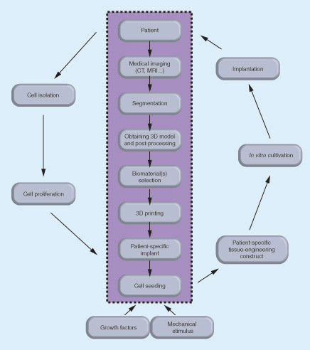
The data obtained from medical imaging of the patient's intervertebral disc (IVD) are segmented and processed into a 3D model to be used in 3D printing the selected biomaterial(s) of a patient-specific IVD implant. Different types of biomaterials can be used for reproducing the annulus fibrosus and nucleus pulposus. The autologous cells are isolated from the patient, proliferated in vitro and introduced into patient-specific scaffold in the presence of growth factors and mechanical stimulus. The tissue engineered patient-specific construct cultured in vitro can be then implanted into the patient.
AF: Annulus fibrosus; IVD: Intervertebral disc; NP: Nucleus pulposus.
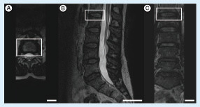
Images taken from the (A) axial, (B) sagittal and (C) coronal planes. The L1–L2 intervertebral disc was indicated by the white rectangle (scale bars: 4 cm).
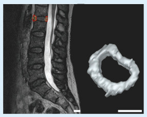
Left: L1–L2 intervertebral disc of the patient. Right: the 3D model of the intervertebral disc after completing the segmentation (scale bars: 2 cm).
The numbers correspond to millimeter.
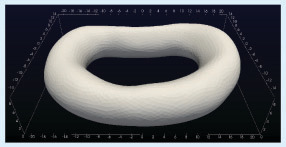
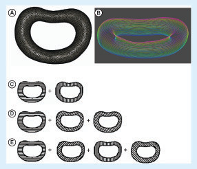
(A) The wireframe 3D model of the intervertebral disc (IVD) of the patient; (B) the layers of the 3D IVD model after slicing of the 3D model into layers with colors changing from red to blue indicating the top and the bottom layer, respectively; the illustration of the alternating layers in the three architectures: architectures A–C with (C) 0°/90°, (D) 0°/60°/120° and (E) 0°/45°/90°/135° strand structures, respectively.
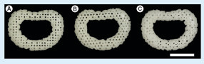
(A) Architecture A (0°/90° strand structure). (B) Architecture B (0°/60°/120° strand structure). (C) Architecture C (0°/45°/90°/135° strand structure) (scale bars: 1 cm).
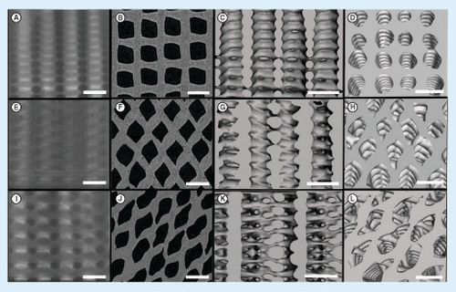
(Top row: A–D) A (0°/90° strand structure), (middle row: E–H), B (0°/60°/120° strand structure) and (bottom row: I–L) C (0°/45°/90°/135° strand structure): the x-ray images (A, E and I), the 2D reconstructed microcomputed tomography images (B, F and J), the 3D reconstructed images showing the structures from side (C, G and K) and top (D, H and L) (scale bars: 1 mm).
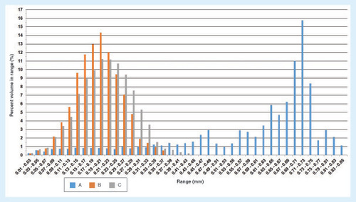
(A) (0°/90° strand structure), (B) (0°/60°/120° strand structure) and (C) (0°/45°/90°/135° strand structure).
First draft submitted: 3 November 2016; Accepted for publication: 26 January 2017; Published online: 3 March 2017
The intervertebral disc (IVD) is a fibrocartilaginous tissue composed of a gelatinous nucleus pulposus (NP) surrounded by the cartilaginous endplates (CEP) on the upper and lower surfaces, and the annulus fibrosus (AF) laterally. The discs are the pivot point of the spine, allowing different direction movements, such as bending, rotating and twisting [Citation1]. The primary functions of IVD are to absorb and distribute unbalanced forces through the ligaments and muscles, and to transmit spine loads that can occur as a result of motions between the vertebral bodies [Citation2,Citation3]. However, the IVD cannot fulfill its normal functions in pathologic conditions such as the loss of disc height (first stage of disc degeneration), endplate-driven or annulus-driven degeneration and disc herniation [Citation4,Citation5], and due to other reasons like physical fitness, bone mass index and smoking [Citation6].
The current treatments mainly include the use of drugs to address the symptoms such as pain and the surgical treatments (i.e., discectomy, spinal fusion, artificial IVD replacement and the use of allogeneic or autogeneic tissues). They neither relieve pain permanently nor regenerate the tissue. Given the reported reherniation, promoted degeneration in adjacent IVDs and the changed biomechanics of the spine after the surgical treatments, it is correct to say that the clinical need has not yet been completely met [Citation7–10]; there is a need for regenerative strategies. Tissue engineering (TE) advanced treatment strategies have promised the restoration of NP [Citation11–15] or AF [Citation16–19] and total disc replacement [Citation19–21]. In simple words, in the desired TE scenario, new tissue formation occurs by extracellular matrix synthesis of implanted cells, while the biodegradable scaffold that carries and hosts the cells degrades over time. Current TE strategies consider that constructs need to have other properties besides mimicking the extracellular matrix (ECM) of the tissues to be regenerated. The importance of developing patient-specific scaffolds is gaining a new impetus [Citation22,Citation23]. The need for having patient-specific IVD scaffolds is evident, given the fact that the size and shape of IVDs vary from patient to patient, and within a patient they vary within the position in the spine [Citation1,Citation24].
Herein, we demonstrate a step-by-step methodology to produce patient-specific scaffolds starting from the patient's MRI data. Moreover, the 3D model obtained by segmentation can also be used for the preparation and elaboration of 3D surgery planning and the assessment of its difficulties by simulating the operation before the surgical procedure [Citation23,Citation25].
3D reconstructions of anatomical structures are indispensable for medical diagnosis, visualization as well as 3D printing of patient-specific implants [Citation22,Citation26,Citation27]. The process of 3D reconstruction of all the relevant tissues is based on the segmentation of medical imaging data. Existing image segmentation methods vary from manual slice-by-slice segmentation to fully automatic ones [Citation28]. Attempts to fully automate the segmentation procedure are often unreliable or targeted on a limited set of specific tissues. On the other hand, interactive segmentation approaches can combine the efficiency, accuracy and repeatability of automatic methods with human expertise and quality assurance. RheumaSCORE [Citation29], developed by Softeco Sismat S.r.l. [Citation30], is a computer-aided diagnosis software tool that supports and assists the user in the diagnosis and the management of chronic diseases, such as rheumatoid arthritis. One of the features is that RheumaSCORE supports an interactive and real-time segmentation tool, based on a variation of the level-set algorithm for the segmentation and morphological identification of the tissues [Citation22,Citation31]. Other free or open source tools that can provide similar image segmentation functionality with RheumaSCORE include ITK-SNAP [Citation32], 3D Slicer [Citation33], GIST [Citation34] and Analyze [Citation35].
The level-set method [Citation36] was employed in our previous work [Citation22]. The level-set approach is a versatile method for the computation and analysis of the motion of an interface Γ, in two or three dimensions. It is based on the representation of a contour as the zero level set of a higher dimensional function, and formulation of the movement of the contour as the evolution of the level-set function. It is aimed to compute and analyze the subsequent motion of Γ under a velocity field ![]() . This velocity can depend on time, position, the geometry of the interface and/or external physics. The interface is captured as the zero level set of a smooth function φ(x,t). The evolving contour/surface can be extracted from the zero level set Γ(x,t) = [(x,t)| φ(x,t) = 0] with φ:Rn → R. The motion function υ(x,t) consists of a combination of two parts:
. This velocity can depend on time, position, the geometry of the interface and/or external physics. The interface is captured as the zero level set of a smooth function φ(x,t). The evolving contour/surface can be extracted from the zero level set Γ(x,t) = [(x,t)| φ(x,t) = 0] with φ:Rn → R. The motion function υ(x,t) consists of a combination of two parts:
where D is a data part that forces the model toward desirable features in the input data; the part ∇·(∇φ/|∇φ|) is the mean curvature of the surface, which forces the surface to have a smaller area; and αε[0,1] is a free parameter that controls the degree of smoothness in the solution. There are several variants and extensions of the level-set method in the literature. One of them is the geodesic level-set method [Citation37], which is used in the software. The distinctive characteristics of this method are that it focuses on a sparse field solver approach, and the speed function D (which acts as the principal ‘force’ that drives the segmentation) is the result of the combination of two terms: Dintensity and Dfuzzy. The term Dintensity is based on the input grayscale value of the voxel x, while the term Dfuzzy describes the affinity between contiguous voxels.
The present study is a part of the patient-specific IVD TE strategy that we envision, as depicted in , that is, we aim to develop a standard methodology using MRI and computer-aided design combined with 3D printing for the fabrication of patient-specific IVD scaffolds from polycaprolactone (PCL) with different internal architectures. The PCL scaffolds were characterized by microcomputed tomography (μ-CT) to evaluate the effects of the internal architecture on the microstructure.
Materials & methods
MRI segmentation & 3D model reconstruction of the human IVD tissue
A 47-year-old male patient underwent an MRI scan in head-first supine position with the use of a 3.0-T scanner (Siemens MAGNETOM Spectra, Munich, Germany) using spin echo T2-weighted sequence. A Digital Imaging and Communication in Medicine (DICOM) dataset with a high spatial resolution was obtained, and the acquisition plane was sagittal. The DICOM dataset had 80 slices with a voxel size of 0.9 × 0.9 × 0.9 mm3 and a slice thickness of 0.9 mm, with an echo time of 145 ms, repetition time of 1400 ms and an echo train length of 64.
The geometry reconstruction pipeline for generating the 3D IVD model consists of three main steps:
Image segmentation – a proprietary software application called RheumaSCORE (v 0.1.16; Softeco Sismat S.r.l., Genova, Italy) was used for the segmentation of the MRI images. Exterior boundaries separate structures of interest and background, while interior boundaries separate anatomical areas which have different features, in other words, the contact areas between the different tissues. The segmentation process is performed with an operator integration to benefit from the use of landmarks for the detection of exterior/interior borders of the contouring areas to separate CEP and AF.
Manual corrections on the segmented images – some manual refinements were needed to improve the accuracy of the segmented images. The user interface of the tool allows manual error corrections after segmentation or during segmentation using the draw/erase mode.
3D reconstruction – from a given 3D scalar field of voxels, all boundary surfaces are to be computed. The 3D model reconstruction was obtained from the segmented images, and the 3D model was converted into a stereolithography format using the software, which includes this 3D model generation and conversion to stereolithography feature.
Fabrication of patient-specific IVD scaffolds
The 3D model of the IVD was isotropically resized to half size to be practical, and sliced into 0.167-mm-thick layers with the software provided by EnvisionTec GmbH (Germany). Using a fourth-generation 3D Bioplotter (EnvisionTec GmbH, Dearborn, Michigan, USA), three patient-specific IVD scaffolds were printed with three different internal architectures resulting from a layer-wise alternating strand directions either as 0°/90° (architecture A), 0°/60°/120° (architecture B) or 0°/45°/90°/135° (architecture C). In each layer, the strands were parallel to each other and 1 mm apart from each other. For printing the scaffolds, PCL (average Mn = 45,000) purchased from Sigma-Aldrich (MO, USA) was melted at 110°C in the cartridge of the 3D Bioplotter and extruded as strands through a 22G heated metal needle, at a speed of 5 mm/s and under the pressure of 5 bar.
μ-CT analysis
Three samples of each of the three architectures were scanned with a high-resolution desktop x-ray μ-CT system (SkyScan 1272; Bruker MicroCT, Kontich, Belgium) for the 3D morphometric analysis. The x-ray source voltage and current were set at 50 kV and 200 μA, respectively. About 800 projections with 10 μm of isotropic pixel size were acquired over a rotation range of 360° with a rotation step of 0.45°. The 2D cross-sectional images were reconstructed from the x-ray projections. On each 2D images, a grayscale threshold of 32–255 was applied, and a region of interest was defined to obtain a volume of interest dataset which was used for the 3D morphometric analysis performed by using the CT Analyser software (version 1.15.4.0) supplied by Bruker MicroCT.
Statistical analysis
Statistical analysis was performed using SPSS® (IBM® SPSS® Statistics version 23.0; IBM, USA). One-way analysis of variance (ANOVA) tests were used to determine the statistically significant differences between the three different architectures in each structural property (i.e., mean pore size, porosity and interconnectivity). The level of significance used was set at p < 0.05 for a 95% CI.
Results & discussion
MRI segmentation & 3D human IVD model reconstruction
The DICOM dataset having 80 3D T2-weighted MRI images with a voxel size of 0.9 × 0.9 × 0.9 mm3 was obtained for the segmentation of the L1–L2 IVD of the patient. shows the MRI images of the patient from different planes. In our work, we utilized the RheumaSCORE software which uses a variation of the level-set algorithm. CEP and AF have similar intensity on the 2D images; therefore, the landmarks were identified manually inside the interest region of the 2D images for the detection of exterior/interior borders of the contouring areas to distinguish CEP and AF. Also, with the use of the presegmentation tool of RheumaSCORE, that is, grayscale thresholding function, it was possible to segment the AF without the NP component of the IVD. From the final image segmentation, a 3D surface model was reconstructed with RheumaSCORE (). A requirement for having high-quality 3D models is to have volumetric images with identical resolution in all dimensions, that is, isotropic. The DICOM images of the patient were almost isotropic and with high spatial resolution. For a precise segmentation, besides having a high spatial resolution, it is also necessary to obtain the accurate geometric structure of the IVD. Based on our work, an MRI with a smaller voxel size was possible to achieve. Nevertheless, a smaller voxel size may cause a high noise that dramatically affects the segmentation quality, and the final outcome can be worse. The high noise results from long acquisition time and involuntary movement of the spine of the patient during the MRI acquisition process.
In this study, T2-weighted MRI was used as medical image visualization and a semiautomatic segmentation was performed for segmentation of the disc, as an alternative to manual and automatic segmentation. Since manual segmentation is a completely operator-dependent and time-consuming process, the manually drawing of the region of interest requires proper skills and adequate software tools with sophisticated graphical user interface [Citation38]. On the other hand, semiautomatic segmentation has been proposed to minimize supervised operator needs of manual segmentation as well as to allow error correction during the segmentation process, unlike automatic segmentation.
Although we have used the acquired 3D IVD model to produce scaffold, the proposed model can be utilized for several other objectives including, but not limited to, finite element modeling [Citation39]. In addition, the 3D models of the IVD and spine may be preferred over the 2D images by the surgeon for the presurgery planning.
In the last decade, level-set methods which have emerged for the segmentation of images [Citation40], are based on a calculus of piecewise constant variational equations. Moreover, the method can represent contours with complex topology and allow any topological changes naturally. Experiments related to the segmentation of the IVDs were performed using the level-set algorithm, and the segmentation method was determined as a semiautomatic mode which uses a combination of supervised active contour segmentation and postprocessing carried out manually in the following slices. In MRI, hard and soft tissues can be roughly discriminated by characteristic scalar values, in other words, grayscale. Thus, they can be quickly computed as isosurfaces, that is, surfaces passing through voxels of the same scalar value. Typically, anatomical structures are in complex shape, and their curved boundary surfaces are essential to preserve. These boundary surfaces are represented by a set of triangles that are convenient to render using graphics hardware. However, CEP and AF have similar scalar values. Therefore, there is a need for some amount of user interaction. To address this issue, we are currently working to develop a methodology to fully automate the IVD segmentation process; this procedure will allow enhancing the accuracy and reproducibility of the segmentation while minimizing workload, user interaction and extensive postprocessing after the segmentation.
3D fabrication of patient-specific IVD scaffolds
The 3D patient-specific IVD model () was obtained by the segmentation of the MRI. The dataset was isotropically resized to half size and sliced into 25 layers possessing a thickness of 0.167 mm each (A & B). Three distinct internal architectures were developed as shown in C–E. The architectures of scaffolds A–C are composed of alternating layers of 0°/90°, 0°/60°/120° and 0°/45°/90°/135° strands, respectively. shows the 3D-printed patient-specific IVD scaffolds with different architectures. Herein, a methodology from MRI acquisition to the 3D-printed IVD scaffolds has been demonstrated to be the critical part of the envisioned patient-specific IVD TE strategy. PCL was selected as the biomaterial for the 3D printing because it is a biomaterial that gathers appropriate properties for rapid prototyping. Once the patient-specific IVD model is obtained, it is possible to tailor the scaffold architecture, as such three basic architectures were studied; and a higher number of different and more complex architectures can be designed.
We have demonstrated a step-by-step methodology to produce patient-specific scaffolds starting from the patient's MRI data. Moreover, the 3D model obtained through segmentation can also be used for the preparation and elaboration of 3D surgery planning and the assessment of its difficulties by simulating the operation before the surgical procedure [Citation23,Citation25]. With the aim of moving further with the knowledge arising from the present studies, the methodology herein demonstrated is currently being investigated for obtaining complex IVD TE implants by means of combining bioinks (e.g., silk fibroin and methacrylated gellan gum hydrogels) and stem cells.
μ-CT analysis of the 3D-printed scaffolds
The structural and morphometric features of the 3D-fabricated samples with the three different architectures were analyzed by μ-CT. The 2D and 3D images are shown in . The μ-CT analysis revealed that the three architectures had similar porosity and interconnectivity, but having different mean pore sizes as summarized in , and the pore size distributions are shown in . ANOVA tests were carried out to investigate if there are any statistically significant differences in each structural feature between the different architectures. The mean pore size was statistically significantly different for each architecture: F(2, 6) = 218.7, p < 0.0005, ω2 = 0.98 and partial η2 = 0.99. Based on the Cohen's effect size benchmarks [Citation41,Citation42], the η2 values of 0.01, 0.06 and 0.14 correspond to small, medium and large effect size classes, respectively. The pairwise differences were investigated with the Tukey's posthoc analysis. There was a statistically significant difference of 165.1 (95% CI: 40.1, 190.1) between architectures A and B (mean [M] = 555.3, standard error [SE] = 9.0) and a difference of 45.5 (95% CI: 20.5, 70.5) in mean pore size between architecture A (M = 600.8, SE = 3.8) and architecture C (M = 435.7, SE = 2.2). When architectures B and C were compared, there was a statistically significant difference of 119.6 (95% CI: 94,6, 144.6; p < 0.0005). The architectures were not statistically significantly different regarding the porosity F(2, 6) = 0.892; p = 0.458, and interconnectivity. F(2, 6) = 1.034; p = 0.411.
The null hypothesis in the ANOVA tests was that the means of the samples with architectures A–C are equal for a structural property; and the alternative hypothesis was that at least the mean of one architecture is different. For the mean pore size, the null hypothesis was rejected, and the alternative hypothesis was accepted since the means of the groups were statistically significantly different; and the null hypothesis cannot be rejected for porosity and interconnectivity.
The entire data were checked for the presence of outliers, normal distribution and homogeneity of variances to ensure statistically valid results by confirming the assumptions that underlie the ANOVA tests were met. There were no outliers as assessed by inspection of a box plot for values of >1.5 box lengths from the edge of the box. The data were normally distributed as determined by Shapiro–Wilk's test (p > 0.05). There was homogeneity of variances confirmed by Levene's test for equality of variances (p = 0.093 for mean pore size, p = 0.716 for porosity, p = 0.241 for interconnectivity).
The size of the pores is one of the important features of a scaffold since it influences the cell attachment, growth and matrix production [Citation43–46]. In the present study, the architecture of PCL scaffolds B and C, which possess micropores, is more adequate for cell culturing as compared with PCL scaffold A (). Rebelo et al. [Citation47] reviewed the cellular morphometry and characteristics of IVD. It was reported that the fibroblasts have the diameter of 1–20 μm and the chondrocytes have the size of around 10–30 μm. The convenience of diffusion and migration of cells is related to relatively larger sized pores, while cell adhesion is related to relatively smaller sized pores since the relative surface area is larger [Citation45]. Matsiko et al. [Citation48] demonstrated that the microarchitecture of the scaffold has a role in differentiation and matrix synthesis of cells. Among the scaffolds they studies, they reported that the scaffolds with the mean pore size of 300 μm provided higher cell growth, like matrix production compared with the scaffolds with the smaller mean pore size that are 94 and 130 μm [Citation48]. Zhang et al. [Citation49] 3D-printed PCL scaffolds with three different mean pore sizes, 215, 320 and 515 μm. The authors reported that the scaffolds with the mean pore size of 215 μm had relatively higher cell growth and matrix synthesis in vitro, and better performance compared with others in vivo [Citation49].
In brief, future studies should further investigate the effect of the scaffold microstructure on the biological and biomechanical performance in a broader manner, that is, considering not only the mean pore size but also the mean porosity and mean wall thickness of the scaffolds.
Conclusion
This study showed a semiautomatic methodology of a geometry reconstruction pipeline from volumetric medical image data to 3D meshes of patient-specific IVD model. The obtained 3D model was 3D printed into scaffolds with different internal architectures. The present work steers us toward the patient-specific IVD TE concept as demonstrated in a way of manufacturing patient-specific scaffolds using the 3D model obtained from the patient's MRI. Furthermore, the obtained patient-specific model could aid in the improvement of clinical and surgical planning before treatment.
Table 1. The structural and morphometric properties of the scaffolds with the three distinct internal architectures of A (0°/90° strand structure), B (0°/60°/120° strand structure) and C (0°/45°/90°/135° strand structure).
The clinical need has not been yet completely met to treat intervertebral disc (IVD) problems, and there is a need for regenerative tissue engineering (TE) strategies.
Scaffolds hold a critical role in IVD TE.
Given the fact that IVDs differ in size and shape, being patient-specific holds a great importance.
To show how to produce patient-specific IVD scaffolds/implants, we presented a methodology for producing such 3D-printed scaffolds from human MRI using a semiautomatic 3D segmentation.
Scaffolds with different internal architectures were produced, and their effect on the microstructure was compared with get preindications on their biological performances with cells.
Medical imaging combined with the 3D-printing technology enables us to proceed directly to produce patient-specific implants from the chosen biomaterial/s.
The results bring us a step closer to the development of patient-specific IVD TE scaffold, and the translation into daily clinical approaches is envisioned with future studies.
Ethical conduct of research
The authors state that they have obtained appropriate institutional review board approval or have followed the principles outlined in the Declaration of Helsinki for all human or animal experimental investigations. Inaddition, for investigations involving human subjects, informed consent hasbeen obtained from the participants involved.
Financial & competing interests disclosure
The authors would like to acknowledge the financial support provided by the Portuguese Foundation for Science and Technology (FCT) through the project EPIDisc (UTAP-EXPL/BBB-ECT/0050/2014), funded in the Framework of the ‘International Collaboratory for Emerging Technologies, CoLab’, UT Austin|Portugal Program. FCT is also acknowledged for the PhD scholarship attributed to IF Cengiz (SFRH/BD/99555/2014) and the financial support provided to J Silva-Correia (SFRH/BPD/100590/2014 and IF/00115/2015). JM Oliveira also thanks the FCT for the funds provided under the program Investigador FCT (IF/00423/2012 and IF/01285/2015). The authors have no other relevant affiliations or financial involvement with any organization or entity with a financial interest in or financial conflict with the subject matter or materials discussed in the manuscript apart from those disclosed.
No writing assistance was utilized in the production of this manuscript.
References
- Shankar H , ScarlettJA, AbramSE. Anatomy and pathophysiology of intervertebral disc disease. Tech. Reg. Anesth. Pain Manag.13(2), 67–75 (2009).
- Silva-Correia J , CorreiaSI, OliveiraJM, ReisRL. Tissue engineering strategies applied in the regeneration of the human intervertebral disk. Biotechnol. Adv.31(8), 1514–1531 (2013).
- Nerurkar NL , ElliottDM, MauckRL. Mechanical design criteria for intervertebral disc tissue engineering. J. Biomech.43(6), 1017–1030 (2010).
- Adams MA , RoughleyPJ. What is intervertebral disc degeneration, and what causes it?Spine31(18), 2151–2161 (2006).
- Adams MA , DolanP. Intervertebral disc degeneration: evidence for two distinct phenotypes. J. Anat.221(6), 497–506 (2012).
- Depalma MJ , KetchumJM, SaulloTR. Multivariable analyses of the relationships between age, gender, and body mass index and the source of chronic low back pain. Pain Med.13(4), 498–506 (2012).
- Lebow RL , AdogwaO, ParkerSL, SharmaA, ChengJ, McgirtMJ. Asymptomatic same-site recurrent disc herniation after lumbar discectomy: results of a prospective longitudinal study with 2-year serial imaging. Spine36(25), 2147–2151 (2011).
- Cowan JA Jr , DimickJB, WainessR, UpchurchGRJr, ChandlerWF, La MarcaF. Changes in utilization of spinal fusion in the United States. Neurosurgery59(1), 15–20 (2006).
- Whatley BR , WenX. Intervertebral disc (IVD): structure, degeneration, repair and regeneration. Mater. Sci. Eng. C32(2), 61–77 (2012).
- Barrey C , PerrinG, ChampainS. Pedicle-screw-based dynamic systems and degenerative lumbar diseases: biomechanical and clinical experiences of dynamic fusion with isobar TTL. ISRN Orthop.2013, 183702 (2013).
- Silva-Correia J , OliveiraJM, CaridadeSGet al. Gellan gum-based hydrogels for intervertebral disc tissue-engineering applications. J. Tissue Eng. Regen. Med.5(6), e97–107 (2011).
- Silva-Correia J , Miranda-GonçalvesV, SalgadoAJet al. Angiogenic potential of gellan-gum-based hydrogels for application in nucleus pulposus regeneration: in vivo study. Tissue Eng. Part A18(11–12), 1203–1212 (2012).
- Pereira D , Silva CorreiaJ, OliveiraJM, ReisR. Hydrogels in acellular and cellular strategies for intervertebral disc regeneration. J. Tissue Eng. Regen. Med.7(2), 85–98 (2013).
- Reitmaier S , KrejaL, GruchenbergKet al. In vivo biofunctional evaluation of hydrogels for disc regeneration. Eur. Spine J.23(1), 19–26 (2014).
- Silva-Correia J , GloriaA, OliveiraMBet al. Rheological and mechanical properties of acellular and cell laden methacrylated gellan gum hydrogels. J. Biomed. Mater. Res. A101(12), 3438–3446 (2013).
- Mizuno H , RoyAK, VacantiCA, KojimaK, UedaM, BonassarLJ. Tissue-engineered composites of anulus fibrosus and nucleus pulposus for intervertebral disc replacement. Spine29(12), 1290–1297 (2004).
- Saad L , SpectorM. Effects of collagen type on the behavior of adult canine annulus fibrosus cells in collagen–glycosaminoglycan scaffolds. J. Biomed. Mater. Res. A71(2), 233–241 (2004).
- Shao X , HunterCJ. Developing an alginate/chitosan hybrid fiber scaffold for annulus fibrosus cells. J. Biomed. Mater. Res. A82(3), 701–710 (2007).
- Van Uden S , Silva-CorreiaJ, CorreloV, OliveiraJ, ReisR. Custom-tailored tissue engineered polycaprolactone scaffolds for total disc replacement. Biofabrication7(1), 015008 (2015).
- Park SH , GilES, MandalBBet al. Annulus fibrosus tissue engineering using lamellar silk scaffolds. J. Tissue Eng. Regen. Med.6(S3), S24–S33 (2012).
- Park SH , GilES, ChoHet al. Intervertebral disk tissue engineering using biphasic silk composite scaffolds. Tissue Eng. Part A18(5–6), 447–458 (2011).
- Cengiz IF , PitikakisM, CesarioLet al. Building the basis for patient-specific meniscal scaffolds: from human knee MRI to fabrication of 3D printed scaffolds. Bioprinting1–2, 1–10 (2016).
- Radenkovic D , SoloukA, SeifalianA. Personalized development of human organs using 3D printing technology. Med. Hypotheses87, 30–33 (2016).
- Lertudomphonwanit T , KeorochanaG, KraiwattanapongC, ChanplakornP, LeelapattanaP, WajanavisitW. Anatomic considerations of intervertebral disc perspective in lumbar posterolateral approach via Kambin's triangle: cadaveric study. Asian Spine J.10(5), 821–827 (2016).
- Cevidanes LH , TuckerS, StynerMet al. Three-dimensional surgical simulation. Am. J. Orthod. Dentofacial Orthop.138(3), 361–371 (2010).
- Gander T , EssigH, MetzlerPet al. Patient specific implants (PSI) in reconstruction of orbital floor and wall fractures. J. Craniomaxillofac. Surg.43(1), 126–130 (2015).
- Kozakiewicz M , ElgalalM, WalkowiakB, StefanczykL. Technical concept of patient-specific, ultrahigh molecular weight polyethylene orbital wall implant. J. Craniomaxillofac. Surg.41(4), 282–290 (2013).
- Pham DL , XuC, PrinceJL. Current methods in medical image segmentation. Annu. Rev. Biomed. Eng.2(1), 315–337 (2000).
- RheumaSCORE . www.research.softeco.it/rheumascore.aspx (2016).
- Softeco Sismat S.r.l . www.softeco.it (2016).
- Parascandolo P , CesarioL, VosillaL, VianoG. Computer aided diagnosis: state-of-the-art and application to musculoskeletal diseases. In: 3D Multiscale Physiological Human. Magnenat-ThalmannN, RatibO, ChoiHF ( Eds). Springer-Verlag, London, UK, 277–296 (2014).
- Yushkevich PA , PivenJ, HazlettHCet al. User-guided 3D active contour segmentation of anatomical structures: significantly improved efficiency and reliability. Neuroimage31(3), 1116–1128 (2006).
- 3Dslicer . www.slicer.org (2016).
- Cates JE , LefohnAE, WhitakerRT. GIST: an interactive, GPU-based level set segmentation tool for 3D medical images. Med. Image Anal.8(3), 217–231 (2004).
- Analyze . www.analyzedirect.com (2016).
- Parascandolo P , CesarioL, VosillaL, PitikakisM, VianoG. Smart Brush: a real time segmentation tool for 3D medical images. Presented at: 8th International Symposium on Image and Signal Processing and Analysis (ISPA). Trieste, Italy, September 4–6, 2013.
- Caselles V , KimmelR, SapiroG. Geodesic active contours. Presented at: Proceedings of the Fifth International Conference on Computer Vision. Cambridge, MA, USA, June 20–23, 1995.
- Wong KP . Medical image segmentation: methods and applications in functional imaging. In: Handbook of Biomedical Image Analysis. SuriJS, WilsonDL, LaxminarayanS ( Eds). Springer-Verlag, London, UK, 111–182 (2005).
- Cortez S , ClaroJCP, AlvesJ. 3D reconstruction of a spinal motion segment from 2D medical images: objective quantification of the geometric accuracy of the FE mesh generation procedure. Presented at: IEEE 3rd Portuguese Meeting in Bioengineering (ENBENG). Braga, Portugal, February 20–23, 2013.
- Kimmel R . Numerical Geometry of Images: Theory, Algorithms, and Applications. Springer-Verlag, NY, USA (2012).
- Cohen J . Statistical Power Analysis for the Behavioral Sciences (2nd Edition)Lawrence Erlbaum Associates, NJ, USA (1988).
- Ellis PD . The Essential Guide to Effect Sizes: Statistical Power, Meta-Analysis, and The Interpretation of Research Results. Cambridge University Press, Cambridge, UK (2010).
- Murphy CM , DuffyGP, SchindelerA, O'brienFJ. Effect of collagen–glycosaminoglycan scaffold pore size on matrix mineralization and cellular behavior in different cell types. J. Biomed. Mater. Res. A104(1), 291–304 (2016).
- Zhang Q , LuH, KawazoeN, ChenG. Pore size effect of collagen scaffolds on cartilage regeneration. Acta Biomater.10(5), 2005–2013 (2014).
- O'brien FJ , HarleyB, YannasIV, GibsonLJ. The effect of pore size on cell adhesion in collagen–GAG scaffolds. Biomaterials26(4), 433–441 (2005).
- Murphy CM , HaughMG, O'brienFJ. The effect of mean pore size on cell attachment, proliferation and migration in collagen–glycosaminoglycan scaffolds for bone tissue engineering. Biomaterials31(3), 461–466 (2010).
- Rebelo MA , AlvesTF, De LimaRet al. Scaffolds and tissue regeneration: an overview of the functional properties of selected organic tissues. J. Biomed. Mat. Res. Part B: Applied Biomaterials104(7), 1483–1494 (2016).
- Matsiko A , GleesonJP, O'brienFJ. Scaffold mean pore size influences mesenchymal stem cell chondrogenic differentiation and matrix deposition. Tissue Eng. Part A21(3–4), 486–497 (2014).
- Zhang ZZ , JiangD, DingJXet al. Role of scaffold mean pore size in meniscus regeneration. Acta Biomater.43, 314–326 (2016).