
Abstract
Aim: The aim of this study is the creation of microlattices with spatial distribution via additive extrusion for medical applications, and investigation of the related software tools. Materials & methods: Three approaches for lattice generation are compared and tested on a standard 3D printer. First, the geometry is filled with cubic cells. Second, infills of standard slicer software are used. Last, a custom solution for infill generation is presented. Results: Printability of the cubic cells is limited to three-times the nozzle orifice diameter. The other two approaches create lattices of high quality compromised of one strand at the size of the nozzle orifice diameter, while only the custom solution can create arbitrary spatial distributions. Conclusion: The involved software tools should have to be optimized for every application, but pave the way for customized and functional parts.
All 3D-printing methods share the workflow of cutting a virtual model into layers in a slicer software and using proprietary strategies for physical modeling. For medical applications, not only the outer appearance but also the inner microstructure is of major importance. Looking at an extrusion-based printing of porous microstructures, this software piece mainly limits achievable structure sizes and distribution, which is necessary, for example, for improving osseointegration. We compared different approaches for this task. First, the structures were created as geometry data, with limited performance. Next, different slicers were compared and evaluated. Smaller regular structures could be created. In the end, we present a custom slicer solution that is capable of printing microlattices of high quality with a complex spatial distribution.
The multitude of 3D-printing methods provides a great opportunity for patient specific implants with functional lattice structures but their software tools for managing the processes are still in the early age [Citation1]. As it will be discussed later, every application requires optimized software tools. the aim of this paper is to point out challenges in the current workflow of fused filament fabrication (FFF) for creation of microlattices. First, basics of the printing method are explained. After that, there is an introduction to the software side of the workflow.
The FFF method is widely used, not only in the private sector but also in industry and even hospitals, due to their low investment cost compared with laser-based technologies [Citation2]. The low costs result from its simple design. Basically, it is a computer-guided kinematic with an extrusion system attached to it. The extrusion system is comprised of a material storage in the form of plastic wire (filament), the drive system and the hot end. The drive system is the only moving part of the extrusion assembly. It pushes the filament into the hot end via an optional cooled section. In the hot end, the material is brought to the molten state and pushed through a nozzle into the build chamber, creating a cylindrical strand. A relative kinematic movement of the nozzle and the print bed in the build chamber allows for the successive buildup of parts with high complexity.
The main advantages of FFF are low cost, wide range of materials and unproblematic print conditions. Materials range from standard materials like polylactic acid to high-performance plastics like polyetheretherketone with extrusion temperatures ranging from 200°C for standard plastics to 400°C for high-performance polymers. At the start of the extrusion, a small amount of filament is wasted. After that, there is nearly no spilled filament, making material use very efficient. Regarding the creation of microlattices, powder in the voids of parts printed by a powder-based system is a problem not occurring in extrusion-based systems. Cleaning of the parts and a high investment in material and material handling systems are not necessary.
Constraints of the process are the limited nozzle orifice sizes, challenging temperature control of the material, as well as precise control of the extruded volume. As the nozzle orifice diameter decreases, forces for extrusion rise due to the higher shear rates in the compression zone of the nozzle. It can be partly overcome by reducing the print speed, which lowers the extrusion speed [Citation3]. The maximal force is limited by the drive system, which currently sets a limit at an orifice diameter of about 150 µm (at 10 mm/s print speed). There is ongoing research on diameters as small as 50 µm (at 10 mm/s print speed) for standard materials [Citation4]. For high-performance plastics used for implants, like polyetheretherketone, 200 µm (at 5 mm/s print speed) could be reached [Citation5]. There exist basic models for flow rate estimation (extruded volume per time), but they only work for steady-state extrusion [Citation6]. There exist many problems regarding start of extrusion with different plastics. Ramping of the material flow is necessary but not implemented in software or hardware.
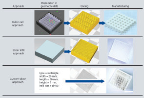
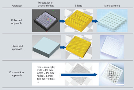
The slicer software cuts surface models into slices (slicing) of specific thickness (layers), which can be printed, layer by layer, based on machine-specific parameters and strategies. The output of the slicer is a machine control file. A format based on NIST RS274 standard [Citation8], commonly referred to as G-Code, is widely used. Challenges with the import of the surface model into the slicer and slicing strategies will be part of the results of this research. One approach will focus on modeled surface data with lattices being sliced (cubic cell approach), while the others focus on the direct creation of lattice structures in the slicer (slicer infill approach) and direct G-code output (custom slicer approach). The software and strategies for the creation of the lattices are described in the following section.
Materials & methods
Input file for slicer software
The industry standard STL format is a tessellated representation of surface data. Thus, curved surfaces are transformed into multiple flat triangles. There is a loss of information and the representation has limited precision and quality [Citation9]. Especially for small structures, the tolerance has to be at least a magnitude lower than the defining structures. The test files for this research were created in NX 11 (Siemens AG) and exported with a triangle tolerance of 0.005 mm. The software for the cubic cell approach has no direct control of the tolerance. The grids were visually tuned to be composed of facets a magnitude lower than the minimum structure size.
Software for lattice generation
Three methods for lattice generation were compared. First, structure definition by repeated cubic cells with special pattern and export to a standard slicer (cubic cell approach). Second, a workaround using infill structures with standard slicer software (slicer infill approach). Third, a self-developed customized slicing solution (custom slicer approach). An overview of the steps involved is given in . Every solution was evaluated by slicing or filling a 20 × 20 × 5 mm3 cuboid with lattice structures. For the cubic cell approach, an inner cube with 1-mm offset to the outer shell was created. The inner lattice was created using Meshmixer 3.2.37. In Meshmixer, a comprehensive edit mode for intersecting variable lattice structures with solid models is available. The resulting tessellated surface (mesh) can be further edited and then exported in various formats, including STL.
Slicers can be machine-specific, universal or both. Cura (Ultimaker B.V.), for example, is a universal slicer which is optimized for the Ultimaker line of machines. Universal slicers, like Simplify3D (Simplify3D, Inc.), are optimized for various machines. A machine-specific slicer like Insight (Stratasys Ltd.) is optimized for their line of fused deposition modeling machines and cannot be used for different machines. We concentrated on universal or standalone software including Cura 2.6.2, Slic3r 1.3, KISSlicer 1.5, CraftWare 1.14 (CraftUnique Ltd.), Mattercontrol 1.7.4 (MatterHackers, Inc.) and Simplify3D 4.0. Cura and Slic3r are open source and can be modified. Except Simplify3D, all the slicer software mentioned are free of charge.
For slicing, if not otherwise described, a constant set of parameters was used. These can be found in .
Table 1. Parameter settings for comparison of the different slicers.
A higher degree of control of the resulting print file can be achieved by direct writing of the machine file (G-Code). It is a simple text-based format. This was done through MATLAB 2016b (The MathWorks, Inc.).
The outputs of the different slicers were printed by an Ultimaker 2+ (Ultimaker B.V.). The material is white polylactic acid with a diameter of 2.85 mm from ‘Das Filament.’ The extrusion temperature was set to 210°C
Results
Cubic cell approach
Structure definition by cubic cells is divided in four qualitative steps from fine to coarse lattice parameters. The parameters are element dimension (strand diameter) and element spacing (distance between strands). Element spacing is chosen to be double the size of the element dimension, creating an evenly distributed lattice of voids and printed strands. The study is starting with an element dimension set to extruder nozzle orifice diameter of 0.4 mm (element spacing 0.8 mm). Then the dimension is increased to create an experimental plan for qualitative comparison. The parameters are listed in .
Table 2. Experimental plan of element dimension and spacing parameters.
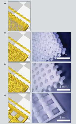
The resulting lattice is exported in STL format and loaded into all the aforementioned slicers for slicing. The single sample contains a lot of artifacts and cannot be sliced properly (see virtual print preview of Cura in , top left). Setting wall thickness to 0.4 mm results in irregular placed dots of material. If infill density is set to 100% with a wall thickness of 0 mm, a random pattern of printed strands becomes visible in the preview window. So, printing is not possible. KISSlicer produces some correct layer slices with mostly regular printed structures but also creates layers with no strands at all. The fine sample has a ring around every void and small irregular filled knots. The sliced result can be printed and features all details of the slicer output. There is a problem with irregular flow between the structural elements. This is caused by the speed damping characteristic of the hot end in contrast to the highly dynamic drive system. Rapid changes in speed propagate slowly through the system and impede manufacturing of small elements at a distance. Material is also flowing between the elements causing strings (commonly referred to as stringing). The medium sample can be printed in good detail. No stringing is visible between the elements. It features a regular infill structure and a solid outer shell following the geometry. The coarse sample visualizes that the staircase effect can be reduced by a higher ratio between layer height and element size. There is a higher circularity tolerance of the printed elements. Fill patterns on top of the structures (angled strands) influence the geometry. Because the quality of the lattices created in this approach is not satisfying, another approach, utilizing the slicer's functions, is examined.
The geometry output from Meshmixer is sliced in Cura and can be seen as a virtual print preview on the left. Printed strands are visualized as cylinders. An image of the printed sample is shown on the right. Some of the outer walls are removed for better view of inner structure. (A) Single sample, (B) fine sample, (C) medium sample and (D) coarse sample.
Slicer infill approach
The different slicers offer various infill methods and parameters for them. A list of available infill types is given in . Most common is an orthogonal lattice of crossing strands called rectilinear, grid or straight infill. In Cura, for example, an alternating infill pattern of crossing infill strands at every layer can be created via a lines infill pattern with infill line directions of 0° and 90° (input setting: [0,90]).
Table 3. Comparison of different slicers regarding infill structures and their modification.
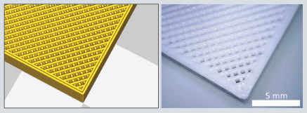
The printed results of the infill grids without any top or bottom layers are good by all slicers. They consist of one strand with a high precision (see ). The strand width is limited by the nozzle orifice diameter. Some irregularities can be observed where the infill strands cross the wall. While traveling between the infill strands, no material is extruded. At the start of the line, the pressure in the hot end is building up again causing a thinner strand dimension or a thicker section due to temperature-induced extrusion (oozing). At the end of the strand, the material is still flowing, creating a thicker end. Simplify3D counteracts this behavior by reducing the extruded amount at the end of the distance.
Preview of sliced output as shown in Cura on the left. Infill density is set to 50% with a rectilinear infill pattern. Isometric view of printed object on the right.
To overcome this issue, there have to be changes in the extruded volume optimized for every type of plastic. But all slicers are still missing higher degree of control over the material flow. Moreover, there is a lack of control over the geometric distribution of the strands. Open-source packages, like Slic3r, can be easily extended with custom-fill strategies, but more complex strategies, like changing the order of printed strands and ramping of material flow (needed for highly regular lattices made of high-performance plastics) make bigger changes in the software necessary. The lack of control of the print strategies makes a customized slicer necessary.
Custom slicer approach
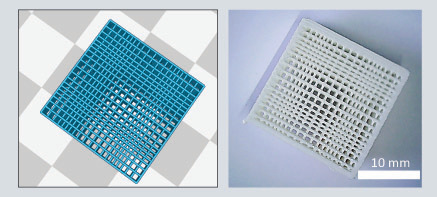
Our created custom slicer consists of scripts creating lines and circles with a filling. They are stored as vector data and can be exported as a G-code file. It is not capable of slicing objects, as this transformation affects precise control of the geometric distribution. But it is useful for research purposes regarding lattice parameters and distribution. The print lines can be directly outputted as G-code and transferred to the machine. Therefore, there is a high degree of control. This results in clean infill structures to the sides without any deformations. All previous infill strategies can be reproduced and more complex ones can be implemented easily. As an example, a bimodal infill is created. The virtual preview and printed object of a bimodal sinusoidal infill is shown in . It has a period of 10 mm creating two dense regions in every direction. The amplitude is set to 1. The values of the sine functions at the element-spacing positions were used as a multiplier for the element spacing. This results in sparser regions where the function is at maximum and vice versa.
Preview of generated G-code loaded in Cura on the left (G-code data import only for visualization). Printed result with bimodal sinusoidal pattern on the right.
Discussion
Different methods for lattice structure definition were presented. The cubic cell approach is highly limited to structures with a minimum feature size of at least three-times the nozzle orifice diameter. An element size of three-times the diameter still features the basic characteristics of the individual layers (staircase effect). Lowering the layer height reduces the effect. Adaptive slicing with individual layer height can partly overcome this issue, but does not lead to smaller scale structures. Advantage of this approach comparing the others is that elements with a different shape than a circular one can be produced.
The slicer infill approach can produce accurate structures at the size and in form of one-strand diameter. Rectangular or rotated rectangular infills can be created. There is a correlation between porosity and infill density, which can be calibrated [Citation10]. So, this approach can be used for research on objects with constant spatial distribution.
Looking for higher complex infill pattern, all slicers are still missing higher degree of control over the spatial distribution of the strands. An option is to divide the body into smaller bodies with a thickness of one slice and set parameters or offsets for every slice. Another option is to alter filling strategy with additional bodies, which define the region to modify. For example, Slic3r (settings > modifier) and Cura (special modes > infill mesh) support this strategy. More complex strategies like changing the order of printed strands and ramping of material flow make bigger changes in the software necessary. Regarding high-performance plastics, the lack of control of the ramping of material made a custom slicer approach necessary.
The solution by the use of the custom slicer can only be used for basic geometric structures. But there is total control over the infill lattice. As an example, a bimodular sine pattern is implemented, showing the capability of this approach. It can be extended to arbitrary functions and used for research on the influences of spatial strand distributions.
Conclusion
The approaches presented only give a small insight into the problems with functional parts produced by extrusion-based technologies. With a focus on small lattice structures, appropriate tools have to be developed for every individual application. The custom slice scripts provide a good solution for simple parts. They can be extended and optimized for more complex parts. Standard slicing solutions do not provide this. This is a result of the current file and software structure. It is not capable of representing the functional aspects of the part. Functionality going beyond mechanical strength is of minor importance, there. A custom slicing solution, like the one shown in this work, creates more complex lattice structures, but up to now lacks the possibility to import complex geometries from, for example, STL files and fill them with complex lattices.
Future perspective
The three approaches showed that software for extrusion-based technologies is still in the early days. There exists a wide variety of commercial and free software. They all have difficulties when transforming CAD model data into the slices. A custom slicing solution for a specific problem provides the highest degree of control over the parts. It is divided into modules for every function. It can be enhanced by optimization strategies, like flow or strength optimization. To bring everything together, new file definitions will have to be developed. Nevertheless, there is a big potential of extrusion-based technologies. With the optimal tools, there is a potential of cheap high-performing parts at a low initial investment cost.
Research on software tools for manufacturing functional parts with small inner lattice structures via additive extrusion processes.
The extrusion process is chosen due to simple system design and wide material range.
Advantage of no material in voids of microlattices is especially important for medical sector.
Three approaches for creation investigated.
Minimal element size of parts compromised of cubic cells with spatial distribution is limited to three-times the nozzle orifice diameter.
State of the art slicers feature capable infill structures and produce good quality orthogonal and regular structures with element size in the range of the nozzle diameter.
A custom slicer writing machine code directly was developed for simple geometries capable of creating more complex spatial distributions of infills.
As a proof of concept, a bimodal sinusoidal infill is presented.
All approached need to be optimized for specific application, but can lead to highly customized parts with functional inner structure.
Financial & competing interests disclosure
The authors have no relevant affiliations or financial involvement with any organization or entity with a financial interest in or financial conflict with the subject matter or materials discussed in the manuscript. This includes employment, consultancies, honoraria, stock ownership or options, expert testimony, grants or patents received or pending, or royalties.
No writing assistance was utilized in the production of this manuscript.
References
- Leong KF , CheahCM, ChuaCK. Solid freeform fabrication of three-dimensional scaffolds for engineering replacement tissues and organs. Biomaterials24(13), 2363–2378 (2003).
- Wohlers T . Wohlers report 2016: 3D printing and additive manufacturing state of the industry. Annual Worldwide Progress Report. Fort Collins, CO, USA (2016).
- Go J , SchiffresSN, StevensAG, HartAJ. Rate limits of additive manufacturing by fused filament fabrication and guidelines for high-throughput system design. Additive Manufacturing16, 1–11 (2017).
- Monzón MD , GibsonI, BenítezAN, LorenzoL, HernándezPM, MarreroMD. Process and material behavior modeling for a new design of micro-additive fused deposition. Int. J. Adv. Manuf. Technol.67(9–12), 2717–2726 (2013).
- Nienhaus V , SpiehlD, DörsamE. Creating lattice structures with polyetheretherketone via additive extrusion processes. Presented at: The Implant Research Center of Drexel University, Exponent Inc. 27–28 April 2017 – Conference transactions and final program. Washington, DC, USA, 15–16 (2017).
- Turner BN , StrongR, GoldAS. A review of melt extrusion additive manufacturing processes: I. Process design and modeling. Rapid Prototyp. J.20(3), 192–204 (2014).
- Christensen A , RybickiFJ. Maintaining safety and efficacy for 3D printing in medicine. 3D. Print. Med.3(1), 200 (2017).
- NISTIR 6556 . The NIST RS274NGC Interpreter – Version 3, NIST Interagency/Internal Report. NISTIR, Gaithersburg, MD, USA (2000).
- Chua CK , LeongKF, LimCS. Rapid Prototyping: Principles and Applications. World Scientific, New Jersey (2003).
- Nienhaus V , LaumannD, SpiehlD, DörsamE. Challenges in the fabrication of optimized microstructures via fused layer modeling. Presented at: 43rd International Research Conference of Iarigai. 24–27 August 2016. Toronto, Canada (2016).