
Abstract
Conclusion: The surface template-assisted marker positioning (STAMP) method is useful for successful Bonebridge™ (BB) implantation on a planned site while avoiding dangerous positions. Objectives: To confirm the usefulness of the STAMP method for the safe operation of BB. Methods: From a patient’s temporal bone CT data, a guide plate and confirmation plate were generated by the STAMP method. The guide plate is used to mark the correct place for implantation, while the confirmation plate lets us know the correct angle and depth of the hole. Results: With the guide plate, the correct place for BB implantation was easily found. The hole was made to be an appropriate size with the confirmation plate while exposing only a small part of sigmoid sinus as simulated. Finally, the BB implant was successfully placed exactly at the planned site.
Introduction
For patients with conductive or mixed hearing loss who cannot use conventional air conduction aids, we usually select percutaneous bone conduction devices. Bone anchored hearing aids (Baha®, Cochlear Ltd, Sydney, Australia) are used most often, but some patients develop skin reaction, wound infection or skin growth over the abutment and implant extrusion [Citation1]. A recently developed device, the Bonebridge™ (BB; MED-EL, Innsbruck, Austria) is a transcutaneous bone conduction implant system designed for adult patients with conductive or mixed hearing loss and good speech discrimination in whom conventional hearing aids are inadequate and reconstructive middle ear surgery is not recommended. It is semi-implantable and the bone conduction implant is positioned completely under the skin. However, the bone conduction-floating mass transducer (BC-FMT) is large (8.7 mm in thickness, 15.8 mm in diameter); therefore deciding on an appropriate location is difficult [Citation2].
Previously, for the Baha® operation, we reported a safe method in which we choose an implant location with enough thickness by 3D-CT with markers [Citation3]. But, since the BB must be embedded into a more dangerous structure, a guide with high accuracy is required. The surface template-assisted marker positioning (STAMP) method is an epoch-making method of carrying out registration using the features of the person’s bone surface, and it is possible for the target part to be shown correctly [Citation4]. Recently, a successful preparatory experiment for applying the STAMP method to BB implantation on cadaveric dry human temporal bones was reported [Citation5]. Ours is the first report to describe the STAMP method applied for actual BB surgery and we were able to implant it safely and accurately into the targeted place.
Material and methods
To perform a BB operation using the STAMP method, the following steps must be carried out [Citation5].
The optimal implant site is determined using a 3D simulation software program ().
The STAMP plates for the surgery are created at Kyushu University (). BB-STAMP plate () indicates an implant site, while the C-STAMP plate () can check whether the hole is an appropriate size for the BC-FMT.
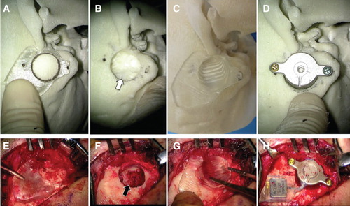
After the bony surface is exposed, the BB-STAMP plate is fitted on the designated location on the temporal bone. Anatomically characteristic landmarks (e.g. zygomatic root) were also used to aid the fit ().
The locations of the BC-FMT and two screws are marked on the bone with a surgical marker pen through the holes of the BB-STAMP plate ().
The temporal bone is drilled at the marked location.
The C-STAMP is used to confirm that the resection procedure is complete ().
The BC-FMT is inserted into the well and screwed at the marked anchor points ().
Figure 1. 3D slicer reconstruction visualizes recommended location of the transducer (red) in the right mastoid (bottom, right). CT scan images show the sagittal (top, left), axial (top, right), and coronal (bottom, left) views with the transducer position (red lines) that is closely located on the sigmoid sinus.
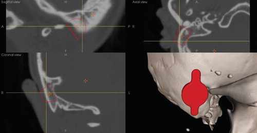
Figure 2. STAMP plates generated from the patient’s CT scan bony surface characteristic data: (A, C) BB-STAMP plate; (B, D) C-STAMP plate. Since this BB-STAMP plate (guide plate) fits only at one place, the big circle can be the guide hole leading to the correct place to make a bony hollow, while small circles indicate the appropriate places for screws. The C-STAMP plate (confirmation plate) can certify the correct size and place of the bed for the BC-FMT: (A, B) surface view; (C, D) back view). BB, Bonebridge; BC-FMT, bone conduction-floating mass transducer; C-STAMP, the C-STAMP can check whether the hole is an appropriate size for the BC-FMT.
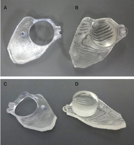
Figure 3. An actual STAMP plate-guided Bonebridge (BB) implantation: (A–D) simulation; (E–H) operation. A temporal bone replica generated from this patient’s CT data was used for this simulation. (A, E) Marking the correct place for BB implantation. The BB-STAMP plate fits only one place on either of the bony surfaces. (B, F) After drilling out of an adequate size of bony hollow. The sigmoid sinus was exposed by the operation (black arrow in F) as was predicted by the simulation (white arrow in B). (C, G) Confirming the hole size and place using the C-STAMP plate. Whether there is enough depth at the right angle can be determined. (D, H) Fixation of the BC-FMT. The transducer fits the hole well and the screw has been fixed to the correct position. BC-FMT, bone conduction-floating mass transducer; C-STAMP, the C-STAMP can check whether the hole is an appropriate size for the BC-FMT.
Results
We have applied this method in a 21-year-old woman with bilateral congenital auricular atresia. She had suffered from conductive hearing loss since birth (air conduction: right 83.3 dB, left 80.0 dB; bone conduction: right 20.0 dB, left 23.3 dB), and underwent an operation for bilateral auricular reconstruction at age 12 but did not undergo canalplasty.
From her CT scan data, 3D temporal bone images were generated, and the optimal implant site was determined to the right side by software (Mimics, Materialise Japan, Tokyo, Japan; ). From these data, a guide plate and confirmation plate indicating an appropriate implant site were generated by the STAMP method (). The created STAMP plates fit only the designated place on the patient’s temporal bone surface; hence, the exact location of the BC-FMT during simulation surgery can be replicated onto the actual patient. To ensure correct fitting, we intentionally included ‘rough’ surface in the STAMP area, such as zygomatic root and anterior wall of the mastoid tip (). The patient did not have bony structure of the external auditory canal ( and ).
The implantation was done under general anesthesia.
After skin incision, a connective tissue flap was made, and the bony surface at the mastoid was exposed. The BB-STAMP plate was assigned to the bone, and the correct place for a good fit was searched for assisted by the typical bone structure of the zygomatic root (). A round mark was put on the guide hole and the mastoid bone was carefully debrided. A small part of the sigmoid sinus was exposed as expected from the simulation (). After checking the size and depth of the hole using a transducer-sizer (T-sizer) included in the surgical kit, the C-STAMP plate was applied to this hole. Because of the slightly different direction, we needed to drill more to precisely fit this plate with the correct angle (). Finally, the coil part of the BB was inserted under the temporal muscle, and the transducer was loaded into the bed. The lug part of the transducer was fixed with regular screws (2 mm diameter, 6 mm long) by a surgical handpiece (W&H Ltd, Bürmoos, Austria; 15 Ncm torque), and the BB implant was successfully placed at the optimal site ().
[Also see our digest video of this operation to confirm a STAMP plate-guided Bonebridge implantation: http://www.shinshu-u.ac.jp/faculty/medicine/chair/ent/BB-STAMP.mp4].
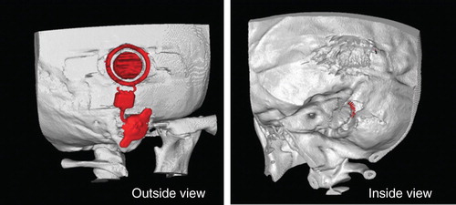
Postoperative CT images indicated that the BC-FMT was successfully implanted at the optimal site with thin exposure to the sigmoid sinus, as expected from the simulation ().
Figure 4. 3D-CT scan images after operation. The Bonebridge (BB) was fixed well on the simulated area without any problem. By inside view, a small part of the bone conduction-floating mass transducer (BC-FMT) was exposed as expected from the simulation to the sigmoid sinus.
Discussion
Both BB and Baha® are recommended as implantable bone conduction solutions for patients with conductive and mixed hearing loss. The Baha® is a simple and attractive system, but exposure of the abutment is sometimes problematic. The BB is an excellent option when a patient wishes that no part of the implanted device be left penetrating the skin. A considerable difficulty of BB implantation is preparing a relatively large enough hole to enclose the BC-FMT, and the ironical fact that BB candidates include those with a congenitally small temporal bone such as the case presented in this report.
Of course, the 3D simulation software for BB has been developed to enable safe implantation. However, since there is no landmark in the actual surgery, the sigmoid sinus and dura are sometimes inadvertently exposed [Citation6]. Alternatively there is also a report of using a navigation system, but the necessary equipment is large and expensive and registration of the temporal bone is difficult; hence, it cannot be said to be useful or practical [Citation7].
The STAMP method we have used here is one of the registration methods with high accuracy in the operation field, and it is already being applied in image-guided otologic surgery [Citation5,8]. It is characterized by high precision and simple template technique due to the registration with the complex unevenness of the bone surface. We applied this STAMP method to an actual operation, and considered how to create a hole of just the right size in which BC-FMT can be fixated in one try in the safe target place. With this useful method, the hole was created exactly in the safe part chosen with 3D simulation software. Although it does take time and effort to create the BB-STAMP plate and C-STAMP plate, this is not a big drawback for BB implantation since these operations are conducted with sufficient preparation periods.
Also, even though precise construction of the plates requires a certain level of expertise and skill, CT data can be sent through the Internet, therefore plates can be reliably made at a central key station and then delivered to the relevant hospitals. The clinical information including the CT data of the reported case was sent to Kyushu University 20 days before implantation. After several discussions over the Internet, the final data for the STAMP plate were sent to the printing center of Ono and Co. in Tokyo via e-mail 7 days before the surgery. The plate was printed and delivered to the Shinshu University Hospital on the next day. The authors had a practice/simulation session using the temporal bone replica of the patient and the STAMP plate before the surgery. If a local 3D printer had been available in Shinshu University, the time for the final printing process would have been minimized. However, since we do not expect emergency cases for BB implantation, this time window was sufficient for us to have multiple simulations in the computer and one simulation using a physical replica with an actual drill.
Skillful fitting of the plate to the bony surface also requires experience. Therefore for the first several times, the surgeon should first practice using a 3D model made from the patient’s own temporal bone CT data [Citation9]. The BB-STAMP plate can be fitted to the contours of the bony surface of the model and the surgeons can actually drill the model during this simulation. This preoperative simulation serves as an excellent practice session before surgery, ensuring optimal results from the actual surgery.
Conclusion
The STAMP method is useful for successful Bonebridge™ implantation on a planned site while avoiding dangerous positions.
Acknowledgments
We are grateful to Miss Kawabata (MED-EL Japan Ltd) for technical advice about the BB implantation. We also thank A.C. Apple-Mathews for help in preparing the manuscript.
Declaration of interest: HO is the CEO of the Ono and Co., Ltd. N.M. and H.O. are co-applicants of a patent related to the STAMP method, and thus, the authors declare this fact as a potential conflict of interest. S. I. is funded by MED-EL Ltd, therefore, the authors declare this fact as a potential conflict of interest. The other authors declare no conflicts of interest.
References
- Dun CAJ, Faber HT, de Wolf MJ, Cremers CW, Hol MK. An overview of different systems: the bone-anchored hearing aid. Adv Otorhinolaryngol 2011;71:22–31.
- Huber AM, Sim JH, Xie YZ, Chatzimichalis M, Ullrich O, Röösli C. The Bonebridge: preclinical evaluation of a new transcutaneously-activated bone anchored hearing device. Hear Res 2013;301:93–9.
- Takumi Y, Suzuki N, Moteki H, Kobayashi K, Usami S. Pre-Baha operation three dimensional computed tomography with markers for determining optimal implant site. Laryngoscope 2008;118:1824–6.
- Matsumoto N, Hong J, Hashizume M, Komune S. A minimally invasive registration method using surface template-assisted marker positioning (STAMP) for image-guided otologic surgery. Otolaryngol Head Neck Surg 2009;140:96–102.
- Cho B, Matsumoto N, Mori M, Komune S, Hashizume M. Image-guided placement of the Bonebridge™ without surgical navigation equipment. Int J Comput Assist Radiol Surg 2014; Epub ahead of print.
- Lassaletta L, Sanchez-Cuadrado I, Muñoz E, Gavilan J. Retrosigmoid implantation of an active bone conduction stimulator in a patient with chronic otitis media. Auris Nasus Larynx 2014;41:84–7.
- Canis M, Ihler F, Blum J, Matthias C. CT-assisted navigation for retrosigmoidal implantation of the Bonebridge. HNO 2013;61:1038–44.
- Matsumoto N, Oka M, Cho B, Hong J, Jinnouchi M, Ouchida R, et al. Cochlear implantation assisted by noninvasive image guidance. Otol Neurotol 2012;33:1333–8.
- Suzuki M, Hagiwara A, Kawaguchi S, Ono H. Application of a rapid-prototyped temporal bone model for surgical planning. Acta Otolaryngol 2005;125:29–32.